Open-Circuit and Short-Circuit Core Losses Computation in a Large Hydro Generator Ana B. M. Aguiar
Arezki Merkhouf
Kamal Al-Haddad
École de Technologie Supérieure 1100 Rue Notre Dame Ouest Montreal, QC H3C 1K1, Canada
[email protected] line
Institut de Recherche Hydro Québec 1800 Boul. Lionel-Boulet Varennes, QC J3X 1S1, Canada
[email protected]
École de Technologie Supérieure 1100 Rue Notre Dame Ouest Montreal, QC H3C 1K1, Canada
[email protected]
Abstract — Predictions of the different magnetic core losses with acceptable accuracy are key parameters for temperaturerise calculations for considered up-rate in large hydro electrical machines. In this paper, available core loss model is used to compute the electromagnetic core losses in large hydro electrical machine during no-load and short-circuit modes. The obtained results are discussed and compared with the available test data. Keywords- flux density, hydro generator, magnetic losses, pole face losses, open circuit and short-circuit.
I.
INTRODUCTION
Availability of powerful computers combined with advanced numerical modeling has opened new opportunities to better understand the electromagnetic phenomena in large hydro electrical generator. In this paper, many electromagnetic studies are carried out with the intent to increase the nameplate rating of selected existing generators. The ultimate goal of this study is to combine electromagnetic, thermal, mechanical and fluid dynamics simulations to replicate numerically the behaviour of the electrical hydro-generators. The open and short-circuit core losses in large hydro generators are major components when calculating the efficiency and temperature rise for any future up-rate. An investigation of open-circuit tooth ripple losses in slotted laminated poles of electrical machines with amortisseur windings has been carried out by [1]. Besides, under open-circuit operation condition, eddy current losses due to axial fluxes were computed in the stator end laminations of a salient-pole synchronous machine using a 3D finite-element package which uses a linear T-φ formulation [2]. Another example of losses studied under open-circuit condition is presented in [3] where the additional losses in the damper windings of hydro generators were calculated using an analytical algorithm. Usually short-circuit simulations are done with the objective of analyzing the stator and damper bar currents behaviour, as in [4]. In this specific paper, the transient operation of a salient pole synchronous generator during an
inter-turn stator fault with different number of shortcircuited turns using FEM was investigated. A comparative analysis of different theoretical iron loss evaluation techniques coupled with finite-element calculations and material modeling has been presented in [5]. The time-domain dynamic-core loss model proposed in [6] was initially applied to compute instantaneous core losses in small electromagnetic devices in both twodimensional and three-dimensional finite element analysis. The model proposed in [6] was extended [7-10] to compute the magnetic-core losses and their corresponding spatial distribution in large hydroelectric generators. The core loss matrix obtained can then transferred to the thermal model to compute the temperature rise in different parts of the generator. The challenge of integrating electromagnetic results with thermal and fluid-flow models was approached and well described in [11]. In present paper, electromagnetic simulations were carried out for open-circuit and short circuit conditions of a large salient-pole synchronous generator. A twodimensional time-stepped finite-element was used during these simulations; besides, the electromagnetic core losses were computed and validated with real data. II.
EXPERIMENTAL MEASUREMENT
The hydro electrical generator under study has the following rating: 122.6 MVA, 13.8 kV, 60 poles and 6 damper bars per pole, and has fractional slots windings. A brief listing of the machine characteristics and design parameters is given in Table I. TABLE I.
GENERATOR DESIGN AND ELECTRICAL PARAMETERS Parameter
General
Stator
Rated speed Rated frequency Power factor Machine active length Air gap length Number of phases Type of connection
Value
Units
120 60 0.9 1626 15.875 3 Y
rpm Hz mm mm
Rotor
Number of slots Number of bars per slot Number of slots/ pole/ phase Number of parallel circuits Phase winding resistance (25 °C) Slot width Slot height Stator outer diameter Stator inner diameter Pole body height Rotor outer diameter Rotor inner diameter Field conductor section Number of turn Field winding resistance (25 °C)
504 2 2 4/5 3 0.00232 23.24 159 11277.6 10617.2 177.8 10585.5 9099.6 402.6 30 0.3369
transfer c is used for measuring losses across the surface that is not covered until the vicinity of the collector compartment. These losses can be calculated by: Ω mm mm mm mm mm mm mm mm2 Ω
A.
Calorimetric method The calorimetric method was performed on a similar machine with the same nameplate and design which were installed at the same power house according to the standard CEI/IEC 34-2 [12]. The machine under study did not have a segregation loss test after it was rewound and restacked with new laminations. However, another unit of the same powerhouse with the same design was measured by calorimetric test. In the similar machine, the old stator laminations (0.4 mm) were restacked and re-insulated. On the other hand, in the studied machine, the stator magnetic material (0.5 mm) and the stator windings were replaced. It is well known that re-insulation of the stator lamination leads to a change in the total stator staking factor, which directly affects the total value of induced magnetic core losses. Because of the changes in stator magnetic material, lamination thickness and the stacking factor, with the studied machine, it is expected to have higher hysteresis losses and lower eddy current losses than the measured one on the similar machine. The calorimetric method is quite straightforward since it relies on the fact that the loss is equal to the sum of the heat added to the water (Pref) and convection (Pconv). The calorimetric method measures the water flow (Q) in each of the cooling circuits and the water temperature at the inlet (Ti) and at the output (To) of the same circuit. Knowing the water specific heat (Cp) and the density of the cooling circuit (ρ), the losses evacuated through the cooling circuit of the generator for a given operation condition can be obtained as follows: P = C · r · Q · DT ref p
[ kW]
(1)
Where Cp is the water specific heat (kj/kg°C), ρ is the water density (kg/m3), Q is the water flow (m3/s) and ∆T is the water temperature variation (°C). Besides, the vertical walls of the generator and all the access doors to the well turbine should be covered with a reflecting heat insulating material. A coefficient of heat
P = conv
S · DT · c 1000
(2)
[ kW]
Where S is the considered exchange surface (m2) and c is the heat transmission coefficient (W/m2°C). More details about the calorimetric method can be found in [12]. For this existing similar machine, the total magnetic losses measured at no-load were 547.6 kW. Besides, the stray loss were measured during short-circuit test as 216.3 kW. All the test results including ventilation and frictions losses for this machine are summarized in Table II.
TABLE II.
Method
Experimental
SEGREGATED LOSSES ON A SIMILAR MACHINE
Description Windage loss Core loss at open-circuit Stray loss Joule (rotor) loss Joule (stator) loss Exciter loss Friction loss Total Losses
Losses (kW) 462.1 547.6 216.3 244.3 228.1 43.1 185.5 1927.0
B. Flux coil measurement Induction coil sensors are the oldest, simplest, low-cost and well-known magnetic sensors available in the industry [13]. Its operating principle results from the Faraday Law of induction where the output voltage V is directly related to the number of turns N and the area A of the coil sensor and the rate of the change of magnetic flux density B.
V = -n
dF dB = -n A dt dt
(3)
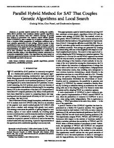
The determination of the magnetic flux density is an indirect measurement; hence the voltage waveform must be integrated over few periods of time. Basically, the typical frequency range of this sensor is from 1 Hz to 1 MHz. The used sensor in our case study was constituted of 10 square winding turns and length side of 0.0254 m. Four coil-sensors were installed in the air gap at 4 symmetrical positions (slots 124, 250, 376 and 502 which correspond respectively to these following positions: 3 h, 6 h, 9 h and 12 h). Fig. 1 shows the integrated flux density measured in air gap (at no-load rated voltage) by the sensors at different locations. It can be observed in this case that the flux density magnitude did not exceed 1.2 Tesla for all sensors.
1,2 1 0,8 0,6 0,4 B[T]
0,2 0 -0,2 0
0,005
0,01
0,015
0,02
0,025
0,03
0,035
0,04
0,045
0,05
-0,4 -0,6 3hrs
-0,8
6hrs 9hrs
-1
12hrs
-1,2 Time [s]
Figure 1. Flux density at no-load for 4 different points of the stator
III.
MAGNETIC CORE LOSS MODEL
Many other core loss models were proposed in the last decade [5-11] that considered the Steinmetz model as a base for the iron separation method. The recent time-domain dynamic core loss model proposed recently in [6] is used in this case study to compute the magnetic core losses. The general equation for this dynamic model is given as follow: 2
dB dB dB Pv (t ) = H irr + kc + k exc dt dt dt
1
2
finite element code using current driven simulation mode. An external circuit (where the load and end windings of the generator are represented by external impedance) is coupled with the transient finite element electromagnetic solution. The end winding impedance was calculated by analytical method that it is well described in [14]. In this paper, the FEA considers the non-linearity of the B-H characteristic curve of the iron core.
A. No-load simulation Electromagnetic simulation was carried out at no-load, rated voltage; figure 3 shows the obtained field lines and magnetic-flux density distribution in the five-pole pitch model of the studied generator given at certain particular rotor position.
(4)
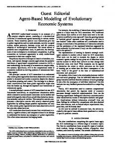
The three terms in (4) are respectively representing the hysteresis, eddy and excess losses given in the time domain. The procedure for determining the irreversible component of the magnetic field in a static hysteresis loop Hirr is the key parameter for computing the hysteresis loss. The expression of the irreversible component Hirr is found in [5], [6]. The loss coefficients for the hysteresis and excess-loss components are derived using the curve regression algorithm with the measured specific core loss curve at different frequencies, as shown in Fig. 2. 600
60 Hz 120 Hz 180 Hz
500
240 Hz
Figure 3. Flux density and flux lines distribution in a 122.6 MVA generator at rated voltage, 13.8 kV, no-load.
The computed radial flux density distribution in the air gap at no-load and rated voltage is shown in Fig. 4, where the stator slotting effect on the magnetic-flux density pulsation in the air gap is clearly observed. Besides, the waveform was analyzed by FFT and the 5th, 7th, 9th harmonics were observed with maximum amplitude of 0.03 Tesla. Other harmonics at multiples of 60 Hz are also observed but at much lower amplitude levels.
360 Hz
1.25
420 Hz 480 Hz
300
540 Hz
0.63
600 Hz 660 Hz
200
720 Hz 780 Hz 100
840 Hz 900 Hz
B_radial [T]
Losses [W/Kg]
300 Hz 400
0.00
-0.63
960 Hz
0 0,0
0,2
0,4
0,6
0,8
1,0
1,2
1,4
1,6
1,8
B [T]
Figure 2. Specific magnetic core loss measured at multiple frequencies with Epstein Test
IV.
PERFOMANCE ANALYSIS
The analysis was performed based on two-dimensional
-1.25 0.00
0.50
1.00
1.50
2.00 Distance [meter]
2.50
3.00
3.50
3.88
Figure. 4. Air gap radial magnetic-flux density of the 122.6 MVA rated voltage generator, no- load mode (B radial function of the air gap distance).
The comparison of the simulated flux density function of time with the experimental data measured at site as shown in
Figure 5 confirmed that the simulation results are in good agreement with the test data. 1,2 0,9 0,6
0,998
0,993
0,988
0,983
0,978
0,973
0,968
0,963
0,958
0,953
0 -0,3
0,948
B [T]
0,3
-0,6 -0,9 Simulated results Measured results
-1,2 Time [s]
Figure 5. Comparison between measured and simulated flux density, at rated voltage, 13.8 kV, no-load (9H sensor).
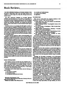
Based on the obtained electromagnetic field solution at rated voltage no-load, the magnetic core losses of the generator are then computed based on the dynamic core loss mode in the time domain and given in (4). Fig. 6 shows the computed magnetic core losses; it is clear from the field obtained solution that the power density is more pronounced in the pole face area specifically around the damper bars. Later, a post processing was performed to separate the losses in the stator and in the rotor and resulted in 391 kW and 151 kW respectively; all the obtained results are summarized in this case in Table III. It can be concluded from these results that the calculated total core losses at noload rated voltage (542 kW) are comparable with the experimental test value (547.6 kW).
B. Short-circuit simulation Electromagnetic simulation was also carried out at steady short circuit condition (rated line current). A post processing operation was performed to separate the magnetic core losses in the stator and in the rotor which resulted in 30 kW and 48 kW respectively. Besides, the damper bar losses (cooper loss) were calculated as 28 kW during steady state short circuit condition. All the obtained numerical results in this case are summarized at Table IV. Finally, the copper stray load losses (extra copper loses) were calculated analytically as 66 kW. Finally, the total computed stray losses for machine in this studied case are around 172 kW which include the damper bar losses (28 kW), pole face losses (48 kW), eddy stator losses (30) and copper stray losses (66 kW). It has to be noted that computed stray loses are 21 % lower compared the measured value (216.3 kW). Therefore, it has to be accounted that the simulation is done using only a 2D model ant the induced core losses in each end the generator are not taken into account; it has to be noted that the losses at end the machine are more pronounced during short circuit test and this can only included in a 3D finite element model. TABLE IV.
SUMMARY OF THE SHORT CIRCUIT CORE LOSS Simulated Results
Excitation Current (A)
Air Gap Magnetic Flux Density Rms (T)
Phase Current (p.u.)
Damper Bar loss (kW)
Rotor Loss (kW)
Stator Loss (kW)
404
0.20
0.992
28
48
30
V. CONCLUSIONS
Figure 6. Core loss distribution of the 122.6 MVA generator, rated voltage, 13.8 kV, no-load TABLE III.
OPEN-CIRCUIT CORE LOSS Simulated Results
Excitation Current (A)
Air Gap Magnetic Flux Density Rms (T)
Voltage (p.u.)
Rotor Loss (kW)
Stator Loss (kW)
467
0.76
1.00
151
391
A 2D Finite Element model was used to compute the core losses during no-load and short-circuit operating condition. The computed parameters are very useful for engineers at design stage or during any considered generator refurbishment. In general the obtained simulation results are in good agreement with the test data; very close in case of case of open circuit condition, and 20 % lower compared to test data in case of steady state three phase short circuit. In order to improve the prediction during short circuit a 3D Finite element should be considered. In the near future, the different obtained core losses will be combined with thermal model to compute the different hot spot temperature in the generator.
REFERENCES [1]
H. C. Karmaker, “Open circuit tooth ripple losses in slotted laminated poles of electrical machines with amortisseur windings,” IEEE
[2]
[3]
[4]
[5]
[6]
[7]
Transactions on Power Apparatus and Systems, vol. PAS-101, no. 5, pp. 1122–1128, 1982. V. C. Silva, G. Meunier, and A. Foggia, “3D Finite-Element Computation of Eddy Currents and Losses in the Stator End Laminations of large Synchronous Machines,” IEEE Transactions on Magnetics, vol. 12, no. 3, pp. 1–4, 1996. G. Traxler-Samek, T. Lugand, and A. Schwery, “Additional Losses in the Damper Winding of Large Hydrogenerators at Open-Circuit and Load Conditions,” IEEE Transactions on Industrial Electronics, vol. 57, no. 1, pp. 154–160, Jan. 2010. S. E. Dallas, A. N. Safacas, and J. C. Kappatou, “A study on the transient operation of a salient pole synchronous generator during an inter-turn stator fault with different number of short-circuited turns using F.E.M.,” International Symposium on Power Electronics Power Electronics, Electrical Drives, Automation and Motion, pp. 1372– 1377, Jun. 2012. O. Bottauscio, A. Cavano “Iron Losses in Electrical Machines: Influence of Different Material Models,” IEEE Trans. on Magnetics, Vol. 38, No.2, March 2002. D. Lin, P. Zhou, and Z.J. Cendes “A Dynamic Core Loss Model for Soft Ferromagnetic and Power Ferrite Materials in Transient Finite Element Analysis”, IEEE Trans. on Magn., Vol. 40, No.2, March 2004 A.B.M., Aguiar, A. Merkhouf, K. Al-Haddad, C. Hudon “Electromagnetic modelling of existing large generator”
[8]
[9]
[10]
[11]
[12]
[13] [14]
International Electric Machines and Drives Conference, IEMDC, Niagara Falls, Canada, pp. 389-393, May 2011. A. Merkhouf, C. Hudon, M. Bélec, E. Guillot, A.B.M., Aguiar, K. AlHaddad, Electromagnetic Loss Computation in Existing Large Hydroelectric Generators International Electric Machines and Drives Conference, Niagara Falls, Canada, May 2011. A.B.M., Aguiar, A. Merkhouf, C. Hudon, K. Al-Haddad “Investigation of the Electromagnetic Simulation Results Variation of a Hydro Electrical Generator.” IECON 2012, pp. 5370-5375, Oct. 2012. A.B.M., Aguiar, A. Merkhouf, C. Hudon, K. Al-Haddad “Influence of the Variation of the Input Parameters on the Simulation Results of Large Hydro Generator” IEEE Trans. Ind. Appl., 2013, accepted for publication. C. Hudon, A. Merkhouf, M. Chaaban, S. Bélanger, F. Torriano, J. Leduc, F. Lafleur., J. F. Morissette, C. Millet, M. Gagné. “Hydrogenerator multi-physic modeling,” European Journal of Electrical Engineering, Vol. 13/5-6 pp.563-589, 2010. "Rotating electrical Machines - Methods for determining losses and efficiency of rotating electrical machines from tests," IE/CEI 342:1972. J. E. Lenz, “A Review of Magnetic Sensors,” Proceedings of the IEEE, vol. 78, no. 6, pp. 973–989, 1990. R. Lin and A. Arkkio, “Calculation and Analysis of Stator EndWinding Leakage Inductance of an Induction Machine,” IEEE Trans. Magn., vol. 45, no. 4, pp. 2009–2014, Apr. 2009.