Stefan Eilemannâ . Silicon Graphics, Inc. ABSTRACT. We describe OpenGL Multipipe SDK (MPK), a toolkit for scalable parallel rendering based on OpenGL.
OpenGL Multipipe SDK: A Toolkit for Scalable Parallel Rendering Praveen Bhaniramka
Philippe C.D. Robert∗
Stefan Eilemann†
Silicon Graphics, Inc.
A BSTRACT We describe OpenGL Multipipe SDK (MPK), a toolkit for scalable parallel rendering based on OpenGL. MPK provides a uniform application programming interface (API) to manage scalable graphics applications across many different graphics subsystems. MPKbased applications run seamlessly from single-processor, singlepipe desktop systems to large multi-processor, multipipe scalable graphics systems. The application is oblivious of the system configuration, which can be specified through a configuration file at run time. To scale application performance, MPK uses a decomposition system that supports different modes for task partitioning and implements optimized GPU-based composition algorithms. MPK also provides a customizable image composition interface, which can be used to apply post-processing algorithms on raw pixel data obtained from executing sub-tasks on multiple graphics pipes in parallel. This can be used to implement parallel versions of any GPUbased algorithm, not necessarily used for rendering. In this paper, we motivate the need for a scalable graphics API and discuss the architecture of MPK. We present MPK’s graphics configuration interface, introduce the notion of compound-based decomposition schemes and describe our implementation. We present some results from our work on a couple of target system architectures and conclude with future directions of research in this area. CR Categories: I.3.2 [Computer Graphics]: Graphics Systems —Distributed Graphics; I.3.7 [Computer Graphics]: ThreeDimensional Graphics and Realism —Virtual Reality Keywords: Scalable Rendering, Parallel Rendering, Immersive Environments, Scalable Graphics Hardware 1
I NTRODUCTION
The need for interactive visualization systems continues to increase constantly. Large amounts of data have to be processed when visualizing complex simulations, rendering large 3D models or scientific data sets [22]. Data sizes in the magnitude of terabytes are not uncommon. In addition, there is a growing need for display technologies, such as CAVEs [13], PowerWalls, domes and other immersive environments. This imposes high requirements on the development and deployment of interactive graphics applications, which have to render at high frame rates and achieve high visual realism. It is desirable that the same application be used in many different environments, ranging from common graphics workstations to high-end visualization systems with multiple graphics pipes and specialized scalable graphics hardware. Multiple graphics pipes can be used to allow graphics-intensive applications to achieve the desired rendering performance and im∗ Now † Now
at the University of Bern, Switzerland at the University of Zurich, Switzerland
IEEE Visualization 2005 October 23-28, Minneapolis, MN, USA 0-7803-9462-3/05/$20.00 ©2005 IEEE.
age quality by executing sub-tasks in parallel and combining partial results generated by individual pipes. Traditionally, proprietary high-end graphics vendors, like SGI and SUN, supported hosting multiple graphics accelerators on one system. With the advent of PCI Express [20], motivated by the needs of the booming video gaming market, this technology can be expected to be more widely available in the future. The advent of modern graphics architectures [37][19], where commodity components are used to build powerful multi-processor, multi-GPU systems, adds to the complexity of modern visualization systems. There is need for a scalable rendering system which enables applications to utilize all available processing and rendering power and reach optimal performance by taking advantage of multiple graphics pipes and other specialized hardware. OpenGL Multipipe SDK (MPK) is a scalable rendering toolkit, which facilitates the development and deployment of parallel, OpenGL-based multipipe applications. MPK-based applications can be configured at run time either via a configuration file or programmatically. By separating the system’s resource management and physical environment from the application, MPK is able to provide applications with run time configurability and scalability. MPK implements compound algorithms based on various decomposition modes and provides a parallel rendering API. Being able to choose and adapt the decomposition strategy for a given problem domain and graphics environment at run time leads to a great amount of flexibility and guarantees that the applications be deployable in a variety of environments. In addition to scalability, MPK allows controlling stereo features of the display environment. It is possible to switch between mono and stereo rendering at run-time allowing MPK applications to run in complex environments and support various input peripherals and projection systems, such as HMDs [39] or BOOMs [25]. MPK is also capable of providing transparent scalability in multi-head X11 environments. We present the architecture of OpenGL Multipipe SDK, and show how it can be used for parallel rendering for a variety of target applications. By separating scene database management from rendering and resource management, we provide run-time configurability and run-time scalability for graphics applications. We introduce a novel way of describing and implementing scalability schemes for parallel graphics applications. Based on that, we design and implement a scalable graphics API. Finally, we show results for GPU-based composition algorithms and extensions to these algorithms to improve scalability and overall rendering performance. MPK currently runs on IRIX, 32-bit Linux and 64-bit Linux platforms. 2
BACKGROUND AND R ELATED W ORK
The field of parallel graphics abounds with literature on attempts to facilitate the development of large-scale visualization and virtual reality applications. Molnar et al. [27] identify three classes of parallel rendering paradigms based on the stage in the rendering pipeline where the sort from object space to screen space occurs: sort-first, sort-middle and sort-last. In the sort-first approach, the screen-space is divided into a number of disjoint display regions which are rendered in parallel and later assembled in the output
119
120
3
G RAPHICS C ONFIGURATION
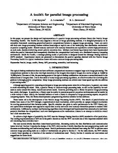
MPK provides the application a high-level view of the underlying system by hiding the details of low-level systemic issues like graphics resource management and parallel rendering. Figure 1 outlines the architecture of a scalable graphics system as viewed by an MPK application. The system consists of a host subsystem and a pool of GPUs connected via a high-bandwidth interconnect. The results generated by the GPUs in the graphics subsystem are distributed across an image composition network, which, after some processing, routes it to the display subsystem. The host is responsible for running the application and controlling other components of the system. The composition network can consist of general-purpose CPUs, GPUs or dedicated composition devices. The architecture does not make any assumptions on the type or topology of the interconnect between the host and the graphics subsystems. Similarly, no restrictions are imposed on the display subsystem, which can either be a set of projectors used to drive a CAVE or a single screen displaying the composited output from the multiple graphics pipes.
CPU 1
CPU 2
CPU 3
CPU p
Memory
Graphics Subsystem
Display Subsystem
GPU 1
Display 1
GPU 2
GPU n
Composition Network
Host Subsystem High Speed Interconnect
frame buffer. In sort-middle, primitives are redistributed between geometry processing and rasterization stages. This straightforward model has been used in many hardware architectures, including InfiniteReality [29], which uses a vertex-data broadcast bus, and Pixel-Planes 5 [15], which uses a ring network to distribute primitives. In sort-last, each graphics pipe renders only a subset of the scene database, preventing any primitive from being rendered more than once. However, image compositing is required to combine the partial results into a single output. Humphrey and Hanrahan [18] describe a virtual graphics system, WireGL, designed to support multiple simultaneous rendering streams to drive large tiled displays. This system was later ported to run on a cluster [16] using traditional sort-first rendering. Humphreys et al. [17] later integrated a parallel rendering interface in WireGL to achieve data scalability. They introduced Chromium [19], a generic system for manipulating streams of graphics commands on clusters of workstations, making it possible to build sortfirst as well as sort-last architectures. Samanta et al. describe a costbased model for load-balancing the rendering tasks among cluster nodes [34]. Later they extend their technique to allow for tile overlap, creating a hybrid sort-first and sort-last algorithm [32]. Since these approaches require full database replication on each cluster node, Samanta et al. compared various data management strategies for clustered environments [33]. CAVELib by Cruz et al. [13] is an API designed for creating interactive multi-screen applications for immersive environments. In 1999, CAVELib was enhanced to support PC-based visualization clusters. VR Juggler [21] [10] is a development and deployment environment for virtual reality applications. Introducing the notion of a virtual platform for VR, Bierbaum et al. implement an operating environment that shields developers from specific details of the underlying hardware architecture and operating system. VR Juggler has also been designed to facilitate run-time reconfigurability [9]. Another toolkit, which supports the development of multipipe applications, is SUN’s multi-display utility MDU [4]. Aside from these highly specialized solutions, high-level toolkits exist which provide at least some support for scalable rendering. OpenGL Performer [31] provides an API for managing multiple graphics pipes, but it does not virtualize the configuration of a multipipe system. Applications have to be aware of the available system resources and use them explicitly in order to take advantage of them. Likewise, Open Inventor applications can make use of immersive environments using TGS’ MultiPipe extension [2]. Head and hand tracking is thereby provided through the Trackd library [5]. Paraview [3], on the other hand, is an application based on VTK [6] which uses a sort-last parallel implementation for scalable visualization of large data sets. Numerous hardware architectures have been proposed for accelerating image composition using specialized hardware. PixelFlow [28] is a proprietary rendering system for real-time image generation, designed to scale linearly with it’s Image Composition Network composed of multiple compositors. Stoll et al. describe Lightning-2 [38], a system to perform composition on a cluster of commercial of-the-shelf (COTS) PCs using the DVI digital video output of commodity GPUs. Similarly, the Metabuffer [11] is a scalable multi-display system for COTS clusters, which includes novel multi-resolution capabilities. The Sepia system from Compaq [26] is a flexible architecture based on programmable FPGA devices to achieve real-time frame rates when rendering partitioned data sets on a cluster of PCs. Similar compositors are available for SGI Onyx and Prism high-performance visualization systems [36]. To leverage the adoption of hardware-based, image-composition solutions using COTS clusters, Alcorn and Frank introduced the Parallel Image Compositing API, called PICA [7]. PICA provides a complete abstraction layer for distributed image composition, independent of the graphics API.
Display 2
Display m
Figure 1: A scalable graphics system
MPK isolates the application from details of the underlying hardware by separating these details from other aspects of the application, like scene database management. The graphics configuration is abstracted using the MPK configuration. Based on this abstraction, MPK implements multiple parallel rendering paradigms using compounds. 3.1
The MPK Configuration
The MPK configuration is a tree-like data structure used to describe the graphics resources on the system, along with information on using these resources to generate the final output image. The run-time execution environment provided by MPK uses the configuration to determine which physical pipes to initialize and manage, what parallel tasks to create and synchronize, and where to send the final rendered image for display. This simple scheme is extremely powerful since it isolates the application from the details of the system architecture on which it is running. Additionally, this high-level abstraction allows MPK to optimize the rendering process for specific target architectures in an application-transparent manner. Figure 2 shows an example of a configuration hierarchy and its various components. Each of these components has a unique identifier, a character string. At the top level, the configuration contains a list of pipes. Each pipe corresponds to a physical rendering engine and is characterized by the name of its display – e.g., the X11 display identifier. Each pipe consists of a set of windows, each representing a single graphics context. A window retains attributes like geometry, display visuals and context handles and also provides the abstraction for a task to be created for parallel rendering. Each window further consists of a set of channels, which provide a view definition of the scene. Each channel defines a viewport in the window where the scene, or a part thereof, will be drawn, including the various projection and display parameters. Channels defined in the
Pipe ":0.0"
Window "window" Channel "channel0"
Channel "channel1"
config { pipe { display ":0.0" window { name "window" viewport [ 0.25 0.25 0.5 0.5] channel { name "channel0" } channel { name "channel1" } } } }
Figure 2: A sample configuration hierarchy
same window render to the same graphics context and use the same rendering thread. The configuration can be loaded at run time using an ASCII configuration file (Figure 2) or created programmatically using the MPK API. The former scheme is more commonly used requiring users to only change the MPK configurations during application development and deployment. Multiple windows per pipe are handy for developing, testing and debugging multi-threaded multi-context applications on single-pipe desktop systems while different multipipe configurations will be used when deploying the application in an immersive environment or parallel rendering. 3.2
Compounds
Compounds describe how the rendering resources are combined to produce the final views. MPK allows decomposing the global rendering task into smaller tasks and assigns these tasks to individual channels for parallel rendering. This task division requires a decomposition scheme to send a subset of the rendering primitives to each channel, get back rendered images from each channel and then composite these to get the final image (Figure 3). The decomposition scheme is abstracted using compounds, which are specified as part of the MPK configuration and hence can be configured using the same ASCII file.
source: channel0
Compound
format
Decomposition
source: channel1
Recomposition
source: channel2
destination: channel0
mode
Figure 3: A compound with 3 channels
Compounds form a tree-like structure which provides an abstraction for the decomposition of the rendering. Multiple compounds can be configured as multi-level compound trees. A compound tree specifies the topology of the (de)composition network as well as the operations to be applied during rendering and image composition. Multiple disjoint compound trees may be used to drive multiple displays. Figure 3 outlines the elements of a compound. The destination channel is the root node of the compound tree where the composed result will be displayed. The composition units – CPUs, GPUs or dedicated composition hardware – combine partial images and route the output image to the destination channel. Source channels represent the leaf nodes and perform the actual rendering. The compound mode specifies the decomposition scheme for the immediate children and the composition operator to be applied to the com-
pound. The compound format controls the pixel data to be transported from the source channel; e.g., some composition schemes need both depth and color data to be transported, while others do not. The compound traversal algorithm allows application-specific load balancing and facilitates task-partitioning algorithms to achieve optimal rendering performances with minimal run-time overhead (Section 6.2). 4
S CALABLE R ENDERING
As explained in 3.2, scalability in MPK is achieved through task decomposition and recomposition algorithms implemented as compounds. MPK supports various parallel rendering modes and by default uses optimized GPU-based composition algorithms. Factors affecting the performance of the application include: scalability of the decomposition algorithm, load balancing between source pipes, latency incurred during composition and the graphics IO overhead. The various factors can sometimes be mutually conflicting. To trade-off these factors to achieve the optimal performance for a given configuration, various heterogenous compounds can be combined to create multi-tier (de)composition trees. This also allows parallel composition algorithms to be implemented since individual compounds typically run in parallel. Multi-level compounds are also necessary to support multi-tier hardware compositors when the number of pipes on the system exceeds the number of inputs allowed by a single device [30]. Below we describe the currently available decomposition modes of MPK. 4.1
Frame Decomposition
In frame decomposition, a frame or view is divided into regions, each of which is assigned a different source pipe for rendering. The following compounds fall in this category: Screen Decomposition In screen decomposition (2D), each pipe renders a smaller part of the screen area. Copying the source images and pasting them side-to-side in the destination channel generates the final image. This operation is easily implemented using dedicated hardware (see 5.4). 2D compounds scale pixel-filllimited applications trivially and can also be used to scale generalpurpose computations using graphics hardware (GPGPU) [1], preventing expensive network communication as on GPU clusters [14]. The graphics I/O requirements of 2D are low, because the source images are small. However, as in [27], the technique has issues with load balancing as the number of pipes increases. Database Decomposition In database decomposition (DB), the scene is rendered in parallel by dividing the rendered data across different graphics pipes. Each pipe renders a subset of the data to generate partial images, which are then composited to generate the final image using depth testing and/or alpha blending; e.g., for volume rendering, the application can partition the volume data into equal bricks, each of which is rendered on a different graphics pipe [8]. The system’s pixel-fill performance, texture download bandwidth, as well as texture memory size scale linearly with this technique. Sub-Pixel Decomposition MPK can be used to parallelize operations at the fragment level by using multi-pass rendering algorithms executed in parallel on different pipes and then combining these partial results in the final composition step. Such a scheme can be used to implement full-scene antialiasing (FSAA) by rendering the scene from slightly different viewpoints and applying a filtering kernel during composition. The number of passes is thereby determined by the number of source channels. MPK allows every
121
channel to be used multiple times to allow higher-order filtering algorithms to be implemented. Eye Decomposition Eye decomposition (EYE) is useful for stereo rendering only, where each pipe renders a particular view (left or right) of the scene. If stereo is active, then each pipe view fills in the right or left buffer of the final rendering. This provides excellent load balancing and scalability for stereo-view rendering, because the scene content is similar for each eye.
cull source channel0
draw source channel0
pre-cull destination channel
assemble destination channel
cull source channel1
draw source channel1
Figure 5: Hierarchical culling using multiple cull threads
4.2
Temporal Decomposition
In contrast to frame decomposition, temporal decomposition balances the workload by scheduling the work on each pipe in sync with that of the other pipes to produce a steady stream of rendered frames. Time scheduling rather than the frame division is the focus here. MPK provide two temporal decomposition algorithms: Frame Multiplexing Frame multiplexing (DPLEX) distributes entire frames to the source pipes over time for parallel processing. It uses pipelining of successive frames by introducing latency in the rendering pipeline. DPLEX scales geometry, pixel-fill performance and host-to-graphics bandwidth, as the workload balance between pipes is intrinsically maintained. However, it has an increased transport delay inherent to frame synchronization required across the pipes and produces a latency of (pipes − 1) frames; i.e., there will be a (pipes − 1) frames delay between a user input and the corresponding output frame. frame N+1
frame N+2
frame N+3
channel2
channel1
channel0
frame N
thread until everything is rendered, implicitly load-balancing the rendering. The source channel images are then recomposed in the same way as in a DB compound. 5
C OMPOUND O PTIMIZATIONS
In this section, we discuss various optimizations introduced in MPK that provide a significant performance increase and help to achieve better scalability. 5.1
Asynchronous Compositions
As the number of pipes increase, the composition overhead soon becomes an issue since the destination channel needs to composite the source images sequentially at the end of the frame. MPK provides an asynchronous composition mode (ASYNC) for minimizing this overhead by pipelining the rendering and composition operations. The composition occurs asynchronously with the frame rendering in individual source channels at the beginning of the next frame, allowing the source channels to render the next frame, while the destination channel is compositing the current one. This process also distributes the frame transport evenly, reducing the impact on the I/O subsystem. For the CULL compound, draw operations occur asynchronously from the cull operations; e.g., if the draw threads render frame N-1, the cull threads work on culling for frame N. Hence, the draw never stalls on the cull operation. This scheme improves performance by introducing an additional frame of latency to the pipeline. Figure 6 compares the execution pipeline without and with this mode.
Figure 4: Data streaming using 3 channels
5.2 Data Streaming Data streaming (3D) is similar to database decomposition in that it divides the scene among multiple pipes. The rendering of the final view is streamed through the available channels, using a series of successive compositions and readbacks for each frame, as shown in Figure 4. Like DPLEX, 3D compounds have a latency of (pipes − 1) frames, but they have low graphics I/O overhead, since each compound needs to read and assemble only one source image at a time. Hence, it is a good replacement of DB decomposition if the increased latency is acceptable. 4.3
Operational Decomposition
MPK can decompose operational parts of the application’s pipeline similar to the rendering process itself. This scheme is used to parallelize the draw and cull operations by using one or more culling threads, in addition to the per-window rendering threads. It is used when the cull operation takes a significant amount of time and additional compute resources are available. This flexible scheme allows multiple cull threads per draw operation, multiple draw threads per compound, as well as hierarchical culling for 2D decompositions (Figure 5). Multiple draw threads per compound are implicitly load balanced: Each draw operation pulls the next data to be rendered from the cull queue and renders it. This is repeated by each draw
122
Dynamic Load Balancing
MPK provides a dynamic load balancing mode for 2D, DB and 3D compounds. This mode automatically computes the viewport or range of the compound’s children based on the rendering time of each compound child of the last finished frame. This results in good load balancing for low-latency compounds, provided that the workload is relatively evenly distributed within the child viewport or range. To have a more precise knowledge about the workload distribution, MPK utilizes the region defined for adaptive readback (see 5.5). Moreover, the tiling scheme for 2D compounds can be configured to adapt to the nature of the data being rendered. It is possible to create load-balanced 2D compounds that use channels on other windows also used for the final display. This cross-usage of rendering resources enables scalability on tiled displays by distributing the rendering uniformly across all rendering resources. 5.3
Pbuffer Rendering
MPK uses pbuffer rendering to provide better resource utilization when scaling graphics applications. For example, typical implementations of DPLEX composition do not allow the destination channel to contribute to the final rendering, limiting the scalability of an N-pipe system to N-1 times a single pipe’s performance. MPK
frame 0
channel0 destination clear draw frame 0 fourth quarter
frame 1
frame 2
frame 0
channel2
channel3
clear
clear
clear
draw frame 0 second quarter
draw frame 0 third quarter
draw frame 0 first quarter
read frame 0
read frame 0
read frame 0
post-assemble frame 0 clear
clear
clear
clear
draw frame 1 fourth quarter
draw frame 1 second quarter
draw frame 1 third quarter
draw frame 1 first quarter
read frame 1
read frame 1
read frame 1
channel1
channel2
channel3
clear
clear
clear
draw frame 0 second quarter
draw frame 0 third quarter
draw frame 0 first quarter
read frame 0 clear
read frame 0 clear
read frame 0 clear
draw frame 1 second quarter
draw frame 1 third quarter
draw frame 1 first quarter
read frame 1
read frame 1
read frame 1
post-assemble frame 1
channel0 destination
latency 1 frame 1
channel1
clear pre-assemble frame 0 draw frame 0 fourth quarter
DPLEX, EYE and FSAA decomposition modes are currently implemented in MPK using the SGI Graphics Compositor [36] or DPLEX option board [35]. Hardware compositors also help in reducing the rendering latency in some composition schemes. The use of this hardware is transparent to the application. 5.5
Adaptive Image Pipeline
At the end of the draw operation, the application can specify the image-space bounding box within the framebuffer that was modified during the draw. MPK uses this information to minimize the pixel transfer overhead for the current frame by only processing this region. MPK further optimizes the image acquisition and composition steps for different graphics hardware using 4-pixelaligned transfers, for example. The bounding box is also used to tune the load balancing algorithm since it provides the load balancer more concrete information about the workload distribution in screen space, leading to better prediction for the subsequent frames. 6
P ROGRAMMING AND E XECUTION M ODEL
frame 2
Figure 6: DB decomposition, without and with asynchronous compositions
prevents this by using a separate pbuffer with the same OpenGL context on the destination window as the visible window. The draw thread renders to the pbuffer while the application calls MPK from the draw callback to render the other channels’ output frames. On the availability of a frame, MPK makes the drawable of the visible window current and assembles the frame. Before returning to the application’s draw callback, the OpenGL state is restored and the pbuffer drawable is made current again. This approach gives maximum scalability with DPLEX and has minimal overhead since it does not require an OpenGL context switch. This is depicted in Figure 7. frame N+1
frame N+2
frame N+3
6.1
channel0
window
frame N
syncDPlex: assemble
glCopyPixels
syncDPlex: assemble
glCopyPixels
channel1
pbuffer
glCopyPixels
Figure 7: Full-scale DPLEX rendering using 2 channels
5.4
MPK’s programming model reflects the natural application framework of OpenGL and isolates the rendering task from resource management by using a callback-based interface. This interface is similar to the popular OpenGL Utility Toolkit (GLUT). The application provides function callbacks for specific tasks while the core of MPK handles the multi-processing aspects of the application. For a number of tasks, such as window creation, frame readback and compound assembly, MPK provides default implementations, which can be replaced by the application. A typical example could be to use compound assembly for GPGPU applications [1], where the final composition step would be used to combine the partial computation results instead of the default assembly. Initialization and exit callbacks are invoked for creating and destroying components (pipes, windows, channels, and compounds) and setting of initial parameter values, like display windows, graphics contexts, etc.. Update callbacks are used for actions to execute during each frame refresh, including the per-channel rendering as well as the updates done on the global context handled by each window. Event callbacks process user input and execute actions for a given input event (mouse, keyboard, etc) for each window.
Hardware Composition
Several composition schemes mentioned in the previous section can be accelerated using special-purpose hardware. These devices prevent the overhead in the image acquisition and composition stages by ingesting the output video signal directly from the source graphics pipes and providing the composited video signal as output. 2D,
Initialization
Figure 8 shows the execution model for a typical MPK application. The execution begins by loading the MPK configuration and initializing the application data. MPK allocates and initializes the various components of the configuration. MPK makes data management easier by allowing applications to store and access data in respective containers for each node in the configuration hierarchy. For example, identifiers like texture objects, display list identifiers, etc., which correspond to a given OpenGL context, can be created and stored using per-window containers and later retrieved in the update callbacks. MPK uses a multi-threaded execution model for parallelizing the rendering process and feeding the multiple graphics pipes in parallel. During configuration initialization, MPK creates threads for each window and manages their synchronization during each frame. Event interception and processing in MPK is centralized in the main application thread and allows event-driven execution or continuous rendering. Event handling can be configured and disabled on a perwindow basis to allow custom event processing for different application scenarios. Applications can select from fork, sproc, and pthread multi-tasking schemes at run time. On NUMA systems, pipe- and window-specific data can be allocated on the same node in the system to prevent unnecessary inter-node communication.
123
6.3
start
window 0
window 1
start thread
start thread
initialize window
initialize window
While rendering a frame, the correct contextual data has to be passed to the application callbacks, depending on latency of the compounds. This is done by maintaining a unique data pointer (referred to as frame data), which is allocated and passed to MPK at the beginning of each frame. Once the data is no longer needed, MPK notifies the application to delete it. Likewise, applications can use a culling infrastructure, where the data describing the frame is produced by the application thread. The frame data is always passed latency-correct to the update callbacks.
load config create windows
initialize config
frame begin update compounds assign tasks
frame end
unlock window threads update window
update window
channel 0 clear
channel 1 clear
channel 0 preassemble
channel 1 preassemble
channel 0 draw
channel 1 draw
channel 0 postassemble
channel 1 postassemble
channel 0 readback
channel 1 readback
channel n clear
channel m clear
7
synchronize swapbuffers swap buffers
swap buffers
event processing
exit ? no
yes
update database
no exit config
stop windows
destroy config
stop
exit window?
no exit window?
yes
yes
stop thread
stop thread
Figure 8: Execution model
6.2
Frame Data
Frame Generation
MPK uses a frame-driven rendering pipeline (Figure 8); i.e. the application tells MPK to produce a new frame and MPK invokes all the callbacks on the configuration’s resources required to produce that frame. Therefore, the rendering is always frame-synchronized. An exception to this rule is the DPLEX compound, where individual rendering threads run unsynchronized for multiple frames to allow overlapped time-multiplexed rendering.
D ISCUSSION
In the previous sections, we described the design and optimizations of MPK aimed at maximum scalability and flexibility. Now we demonstrate that MPK-based applications indeed meet these requirements. Using a typical, MPK-based volume rendering application, we present results for a few commonly used compounds. All the results have been generated by using different configuration files with the same unmodified application. We compare these results with the theorical performance numbers and show how optimizations built into MPK help achieve better scalability. The results collected in this paper come from two systems running Linux: an SGI Prism system with 10 Intel Itanium2 processors, 8 ATI FireGL X3 graphics pipes (AGP 8x) and 9.35 GB memory, and a COTS workstation with 1 AMD Opteron 3000+ processor, 2 NVidia GeForce 6600 graphics pipes (PCIe x16) and 2 GB memory. The achieved performance depends on the single-pipe rendering time t1 , readback rate Rr , draw rate Rd and the number of pixels in the destination channel nPixels. Please note that the source channel readbacks are executed in parallel whereas the destination draws are done sequentially. Also note that for asynchronous compounds, the readback and draws are executed in parallel, whereas, for synchronous compounds, they are executed serially (see Figure 6). Hence, for np pipes, assuming linear scalability, perfect load balancing and using the destination channel as a source as well, the theoretical achievable performance for ASYNC and NO ASYNC is given by the following: ttotal
async
=
noasync
=
ttotal
124
(1) (2)
For 2D compounds, tread and tdraw are given by the following: nPixels nPixels , tdraw = (np − 1) · (3) np · Rr np · Rd whereas, for DB compounds, assuming full-screen reads and draws, the corresponding values are the following: tread =
nPixels nPixels , tdraw = (np − 1) · (4) Rr Rd For the tests on the SGI Prism, we have the following characteristics: t1 = 603ms, nPixels = 1280 · 1024, Rr = 68MPixels/s and Rd = 148MPixels/s. Figures 9(a) and 9(b) show the theoretical and measured numbers for 2D and DB compounds, respectively. The NOCOPY graph shows the performance if no software readback or compositing is done, i.e., without the composition overhead. Typically, this is the case when using a hardware compositing device. 2D compounds provide better scalability than DB compounds, if there is perfect load-balancing and the data fits into GPU memory, which is unfortunately not true for most real-world applications. MPK’s timing-based load-balancer provides a better decomposition for such applications, provided they maintain a reasonable tread =
At the beginning of a frame, MPK performs several steps to prepare the compound trees for the rendering. First, each tree is traversed to update the contextual data – like viewport (2D) or range (DB/3D) for the current frame. The next traversal prepares empty input and output frames as well as cull queues as specified by the compound flags and the rendering operations. In the last traversal, the appropriate rendering tasks (like pre- and post-assemble, clear, cull and draw) are assigned to each compound. Now the frame is ready to be rendered. By unlocking the window threads, each rendering channel traverses the compound tree and executes the tasks which are assigned to it by its referencing compounds. When this is done, each window notifies the application thread, so that MPK can synchronize the swapbuffer for all the contributing windows.
t1 + max (tread ,tdraw ) np t1 +t +t np read draw
ASYNC ASYNC IDEAL 15FPS
NO ASYNC NO ASYNC IDEAL
NOCOPY
LINEAR
1-pipe 2-pipe 2D 2-pipe DB
12FPS
NO ASYNC 0.979 1.785 0.962
ASYNC 0.979 1.860 1.764
NOCOPY 0.979 1.951 1.949
LINEAR 0.979 1.958 1.958
Table 1: Achieved frames per second on the dual PCI Express system.
9FPS 6FPS 3FPS
0FPS 1p
2p
3p
4p
5p
6p
7p
8p
15FPS
12FPS
Please note that compounds like 2D, EYE and DPLEX require minimal programming effort and have smaller composition overhead. However, these compounds are limited when handling large data sets. DB and 3D compounds remove these limitations, but they require more application awareness in partitioning the data set across source channels and compositing the partial results. Depending on the problem, data size and system configuration, different compounds might be more applicable.
9FPS
8
C ONCLUSIONS
6FPS 3FPS
0FPS 1p
2p
3p
4p
5p
6p
7p
8p
Figure 9: Performance results using 2D decompositions (top) and DB decompositions (bottom)
frame consistency, both spatially and time-wise. Applications can provide their own load balancing scheme based on their extended knowledge about the rendered data. The performance drop in Figure 9(b) for the NO ASYNC case is an application-specific anomality caused by a suboptimal implementation of the test application. DB
2D
DPLEX
Hybrid 2D-DB
2-stage DB
90.0ms
67.5ms
45.0ms
22.5ms
0ms 2p
4p
6p
8p
Figure 10: Composition overhead for different compounds
Figure 10 compares only the measured overhead incurred by various compounds using ASYNC mode, i.e., t1 = 0. It can be seen that for 2D and DPLEX, the overhead remains almost constant as np increases, whereas for DB, the overhead increases almost linearly (extreme case since the complete viewports are being read and composited). Using a hybrid 2D/DB (similar to Binary Swap [23]) or a multi-stage hierarchical DB composition scheme reduces the overhead considerably by distributing the pixel transfer overhead as well as parallelizing the compositions. Table 1 shows the results obtained on the Dual PCIe system with t1 = 1021ms and Rr = Rd = 190MPixel/s. The advantage of using ASYNC composition is clear, specially for DB compounds where the overhead of composition is higher.
In this paper, we have presented OpenGL Multipipe SDK, a toolkit for parallel scalable rendering. MPK provides applications with a high-level abstraction to the system’s graphics resources while making low-level optimizations behind the scenes. Unlike application-transparent systems like ATI’s CrossFire, Nvidia’s SLI or Chromium, MPK requires parts of an application to be rewritten to take advantage of MPK’s advanced scalability features. This application-aware approach prevents the overhead incurred by application-transparent approaches to get better scalability. At the most generic level, an application only needs to deal with OpenGL rendering areas – i.e., channels – by providing the drawing code to handle a channel of arbitrary configuration (frustum, location in larger display setup, etc.). Everything else is handled by MPK: the type of windowing system, the system architecture, the type and topology of the interconnect. The architecture as such does not depend on the use of OpenGL. MPK’s flexible compound-based decomposition system can be configured to scale any kind of target applications. The compound traversal scheme implements new techniques to provide better scalability for applications. The callback-driven programming model coupled with the frame-driven execution model of MPK is extremely easy to use and intuitive for OpenGL application developers. We have presented scalability results for a few commonly used compounds and shown how asynchronous composition and multilevel compound heirarchies can be configured to scale applications by removing limitations inherent with certain compounds. 9
F UTURE W ORK
Our experiments with the dual-PCI Express system were limited by the availability of only 2 PCIe x16 slots on the system. We are currently investigating several approaches to enable distributed rendering using MPK on a cluster of PCs – e.g., using MPI or TCP/IP for distributing the rendering pipeline over the network. Additionally, using modified Chromium SPUs, we envision an integration where MPK can be used to configure and drive unmodified applications using the Chromium framework. We are also looking into new, more optimal algorithms for DB compositing to reduce the composition overhead and provide better scalability. Fragment shaders and highly tuned, parallel software implementations are approaches that we are currently investigating. Sub-pixel decomposition is a relatively new addition to MPK and we are investigating ways to make it more accessible to end users. Using this approach, applications can provide scalable visual effects like a large number of light sources by rendering a subset of
125
light sources on each source channel or scalable fragment shaders by splitting the shading passes across source channels. While MPK is able to scale GPGPU applications using 2D and DB compounds and custom composition implementations, it does not yet automate scalability for GPGPU applications. This could be addressed by implementing specialized compounds for processing multiple data streams in parallel, eventually using tools like BrookGPU [12] or Sh [24]. 10
ACKNOWLEDGEMENTS
The authors would like to thank Patrick Bouchaud for his efforts he put into MPK. We would also like to thank Vaibhav Saxena, Marc Romankewicz, Ken Jones, Bruno Stefanizzi (all SGI), Hanspeter Bieri (University of Bern, Switzerland), Mike Houston (Stanford University) and other reviewers for their valuable assistance and discussions. R EFERENCES [1] General-Purpose Computation using Graphics Hardware. http://www.gpgpu.org [2] Multi-Pipe Extension for Open Inventor. http://www.tgs.com/ [3] ParaView. http://www.paraview.org [4] Sun Multi-Display Utilities. http://www.sun.com/software/graphics/opengl/mdu/ [5] TrackD API. http://www.vrco.com/trackd/Overviewtrackd.html [6] J. Ahrens, C. Law, W. Schroeder, K. Martin, and M. Papka. A Parallel Approach for Efficiently Visualizing Extremely Large, Time-Varying Datasets. Technical Report LAUR-00-1620, Los Alamos National Laboratory, 2000. [7] B. Alcorn and R. Frank. Parallel Image Compositing API. Workshop on Commodity-Based Visualization Clusters, October 2002. [8] P. Bhaniramka and Y. Demange. OpenGL Volumizer: A Toolkit for High Quality Volume Rendering of Large Data Sets. Proceedings of the 2002 IEEE Symposium on Volume Visualization and Graphics, pages 45–54, 2002. [9] A. Bierbaum and C. Cruz-Neira. Run-Time Reconfiguration in VR Juggler. 4th Immersive Projection Technology Workshop, June 2000. [10] A. Bierbaum, C. Just, P. Hartling, K. Meinert, A. Baker, and C. CruzNeira. VR Juggler: A Virtual Platform for Virtual Reality Application Development. Proceedings of IEEE Virtual Reality 2001, March 2001. [11] W. Blanke, C. Bajaj, D.Fussel, and X. Zhang. The Metabuffer: A Scalable Multi-Resolution 3-D Graphics System Using Commodity Rendering Engines. Technical Report TR2000-16, University of Texas at Austin, 2000. [12] I. Buck, T. Foley, D. Horn, J. Sugerman, K. Fatahalian, M. Houston, and P. Hanrahan. Brook for GPUs: Stream Computing on Graphics Hardware. Proceedings of SIGGRAPH 2004, 23(3):777–786, 2004. [13] C. Cruz-Neira, D. Sandin, and T. DeFanti. Surround-Screen Projection-Based Virtual Reality: The Design and Implementation of the CAVE. Proceedings of SIGGRAPH 93, pages 135–142, 1993. [14] Z. Fan, F. Qiu, A. Kaufman, and S. Yoakum-Stover. GPU Cluster for High Performance Computing. Proceedings of the ACM/IEEE SC2004 Conference, page 47, 2004. [15] H. Fuchs, J. Oulton, J. Eyles, T. Greer, J. Goldfeather, D. Ellsworth, S. Molnar, G. Turk, B. Tebbs, and L. Israel. Pixel-Planes 5: A Heterogeneous Multiprocessor Graphics System Using Processor-Enhanced Memories. Proceedings of SIGGRAPH 89, pages 79–88, July 1989. [16] G. Humphreys, I. Buck, M. Eldridge, and P. Hanrahan. Distributed Rendering for Scalable Displays. IEEE Supercomputing, October 2000. [17] G. Humphreys, M. Eldridge, I. Buck, G. Stoll, M. Everett, and P. Hanrahan. WireGL: A Scalable Graphics System for Clusters. Proceedings of SIGGRAPH 2001, pages 129–140, August 2001.
126
[18] G. Humphreys and P. Hanrahan. A Distributed Graphics System for Large Tiled Displays. IEEE Visualization 1999, pages 215–224, October 1999. [19] G. Humphreys, M. Houston, R. Ng, R. Frank, S. Ahern, and P. D. Kirchner. Chromium: A Stream-Processing Framework for Interactive Rendering on Clusters. ACM Transactions on Graphics, 21(3):693–702, 2002. [20] Intel Corporation. The PCI Express Architecture and Advanced Switching, 2003. [21] C. Just, A. Bierbaum, A. Baker, and C. Cruz-Neira. VR Juggler: A Framework for Virtual Reality Development. 2nd Immersive Projection Technology Workshop, May 1998. [22] M. Levoy, K. Pulli, B. Curless, S. Rusinkiewicz, D. Koller, L. Pereira, M. Ginzton, S. Anderson, J. Davis, J. Ginsberg, J. Shade, and D. Fulk. The Digital Michelangelo Project: 3D Scanning of Large Statues. Proceedings of SIGGRAPH 2000, pages 131–144, July 2000. [23] K.-L. Ma, J. S. Painter, C. D. Hansen, and M. F. Krogh. Parallel Volume Rendering Using Binary-Swap Image Composition. IEEE Computer Graphics and Algorithms, July 1994. [24] M. D. McCool, Z. Qin, and T. S. Popa. Shader Metaprogramming. Proceedings of the ACM SIGGRAPH/Eurographics Conference on Graphics Hardware, pages 57–68, 2002. [25] I. E. McDowall, M. T. Bolas, S. D. Pieper, S. S. Fisher, and J. Humphries. Implementation and Integration of a Counterbalanced CRT-based Stereoscopic Display for Interactive Viewpoint Control in Virtual-Environment Applications. Proc. SPIE, 1256, 1990. [26] L. Moll, A. Heirich, and M. Shand. Sepia: Scalable 3D Compositing using PCI Pamette. Proceedings of the Seventh Annual IEEE Symposium on Field-Programmable Custom Computing Machines, page 146, 1999. [27] S. Molnar, M. Cox, D. Ellsworth, and H. Fuchs. A Sorting Classification of Parallel Rendering. IEEE Computer Graphics and Algorithms, pages 23–32, July 1994. [28] S. Molnar, J. Eyles, and J. Poulton. PixelFlow: High-Speed Rendering Using Image Composition. Proceedings of SIGGRAPH 92, pages 231–240, August 1992. [29] J. S. Montrym, D. R. Baum, D. L. Dignam, and C. J. Migdal. InfiniteReality: A Real-Time Graphics System. Proceedings of SIGGRAPH 97, pages 293–302, August 1997. [30] J. Nonaka, N. Kukimoto, N. Sakamoto, H. Hazama, Y. Watashiba, X. Liu, M. Ogata, M. Kanazawa, and K. Koyamada. Hybrid Hardware-Accelerated Image Composition for Sort-Last Parallel Rendering on Graphics Clusters with Commodity Image Compositor. IEEE Volume Visualization Symposium, 2004. [31] J. Rohlf and J. Helman. IRIS Performer: A High Performance Multiprocessing Toolkit for Real-Time 3D Graphics. Proceedings of SIGGRAPH 94, pages 381–395, July 1994. [32] R. Samanta, T. Funkhouser, K. Li, and J. P. Singh. Hybrid Sort-First and Sort-Last Parallel Rendering with a Cluster of PCs. Proceedings of Eurographics Workshop on Graphics Hardware, pages 97–108, August 2000. [33] R. Samanta, T. Funkhouser, K. Li, and J. P. Singh. Sort-First Parallel Rendering with a Cluster of PCs. SIGGRAPH 2000 Technical Sketch, August 2000. [34] R. Samanta, J. Zheng, T. Funkhouser, K. Li, and J. P. Singh. Load Balancing for Multi-Projector Rendering Systems. Proceedings of Eurographics Workshop on Graphics Hardware, pages 107–116, August 1999. [35] Silicon Graphics, Inc. Onyx2 DPLEX Option Hardware User’s Guide, 1999. [36] Silicon Graphics, Inc. SGI InfinitePerformance: Scalable Graphics Compositor User’s Guide, 2002. [37] Silicon Graphics, Inc. Silicon Graphics Prism Family of Visualization Systems, 2004. [38] G. Stoll, M. Eldridge, D. Patterson, A. Webb, S. Berman, R. Levy, C. Caywood, M. Taveira, S. Hunt, and P. Hanrahan. Lightning-2: A High-Performance Display Subsystem for PC Clusters. Proceedings of SIGGRAPH 2001, pages 141–148, August 2001. [39] M. A. Teitel. The Eyephone: A Head Mounted Stereo Display. Proc. SPIE, 1256:168–172, 1990.