OPENSIMKIT - AN OPEN-SOURCE SYSTEM SIMULATION ENVIRONMENT APPLIED TO SPACE PROJECTS Jens Eickhoff (1), Michael Fritz (2), Rouven Witt (2), Ivan Kossev (2), Mario Kobald (2), Alexander Brandt (3) (1) Immenstaad, Germany,
[email protected] (2) Stuttgart, Germany (3) Munich, Germany www.opensimkit.org ABSTRACT OpenSimKit is a free system simulation software under GNU Public License written in Java. It has initially been developed for teaching purposes at the University of Stuttgart. It provides the functionality to simulate systems based on their numerics fully reflecting the system topology in the input file. The example application supplied with the software distribution represents a rocket upper stage including orbit and simple attitude dynamics as well as full internal propulsion system physics. The astrodynamics propagator uses libraries from NASA's open-source Java Astrodynamics Toolkit (JAT). OpenSimKit is supported by a graphical user interface. Since OpenSimKit v3.5.0 the simulated rocket stage can be visualized by connecting the simulator to the 3D astronomy program Celestia. OpenSimKit is developed by students, engineers and IT-workers investing their spare time. Capabilities and limits provided by the current release are illustrated and the future roadmap is outlined. 1. INTRODUCTION Today complex systems like spacecraft are developed applying system simulation technologies [1]. In order to familiarize students with these technologies and to provide hands-on experience, OpenSimKit has been developed as an add-on support for lectures and seminars. Students contributing to this project gain a practical insight to simulator technologies without being overloaded by too many detailed features of industrial tools. The latter in addition usually neither do reveal their simulator core sources nor give an insight into certain models or libraries. Thus, they are suited for students to conduct simulations, but are inappropriate for learning how to build simulators. OpenSimKit provides the functionality to simulate complex systems by modeling their system topology. Additionally the OpenSimKit kernel has the ability to solve differential equation systems (DEQ) on system level, both solving initial value problems (e.g. spacecraft orbit propagation) as well as boundary value problems (e.g. hydraulic boundary conditions in a
spacecraft propulsion system or in space station life support systems). The simulation can be commanded by a graphical user interface. The latest OpenSimKit release also provides the feature of visualizing a simulated spacecraft in orbit applying the astrodynamics tool Celestia as a “3DViewer“ [2]. Both industry and students benefit from qualifying students in this area. By the contribution of a dozen of students, engineers and IT-workers investing their spare time, OpenSimKit rapidly evolved in the last two years. Developer weekends hosted at the University of Stuttgart supported the communication between developers and enhanced the whole development process. Nevertheless there are many sectors open for future improvement which will be presented and discussed. 2. OVERVIEW Figure 1 provides an overview on application functionalities and their interactions. It illustrates the simple handling and dynamic configuration of OpenSimKit. The elements are described in the following sections. 3. INSTALLING THE SOFTWARE The OpenSimKit software is designed for easy installation and removal: 1. Download source code from the project web page www.opensimkit.org. 2. Unzip the archive into a convenient directory on the harddisk, which results in unpacking the OpenSimKit top-level directory with its subdirectories. 3. Compile the OpenSimKit programs and libraries with the shell command “ant all“ inside the “build“ subdirectory. 4. After finishing the compilation, OpenSimKit simulation is available in the “work“ subdirectory. 5. For removing simply delete the OpenSimKit top level directory. OpenSimKit does not install any .so or .dll libraries or suchlike anywhere in the operating system.
Figure 1. System overview Apache Ant is the only tool needed to build OpenSimKit, besides the Java Development Kit. All other libraries are delivered within the current release. Emphasis was put on exclusively using licensecompatible open-source libraries to keep the complete delivered package open-source as well. 4. CONFIGURING THE SIMULATOR Both the simulated system layout and parametrization as well as configuration of the simulation scenario can be handled in a single XML file. Changing the topology of the simulated system or equipment model parameters does not impose any input deck recompilation. An input file consists of five sections: System definitions, model definitions, equipment interconnections, boundary problem DEQ solver meshes and log file output. A system description, a time management configuration and simulation control belong to the first section. The time management provided by the time handler enables to set simulated mission time as well as real and simulated integration interval. Component models and associated variables are configured in the second section. Connections between the models like pipes are to be defined in the following one. The fourth section allows to set meshes and the last one configures the log file output.
5. MODELING INTERNAL PHYSICS The example application for a simulated system included in the current OpenSimKit release is the implemented rocket stage system depicted in Figure 2. Its engine is reignitable and powered by N2O4 and MMH or Aerozine 50 and the design is an approximation of the former European ELDO Astris1 stage. A part of the model is a descendant from [3]. Helium gas, high pressure bottles, pressure drop in pipes, junctions, filters, pressure regulators, flow valves, an engine and an engine controller are included. The propellant and oxidizer tank are modeled reflecting all real-gas thermodynamics in the differential equation systems. Details on all models are described in [2]. However the OpenSimKit system architecture is not limited to modeling rockets. It can also be applied to modeling other types of thermo-fluiddynamic systems like fuel cells etc.
1
Astris was the upper stage of the Europa rocket.
Figure 3. OpenSimKit graphical user interface
Figure 2. Modeled rocket propulsion system
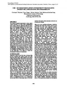
6. ASTRODYNAMICS PROPAGATOR OpenSimKit's astrodynamics propagator uses extracts from NASA's Java Astrodynamics Toolkit (JAT) which supports the gravity model. The spacecraft is modeled as firm-fixed body structure with a local body frame coordinate system onto which forces (engine thrust, gravity acceleration) and torques are applied. RungeKutta integrators are applied to compute acceleration, velocity and position in an Earth Centered Inertial (ECI) coordinate system. Velocity and position are transformed both to an Earth-Centered, Earth-Fixed (ECEF) coordinate system and to latitude, longitude and altitude values by applying the corresponding functions from the Java Astrodynamics Toolkit. Such parameters can be used to visualize the spacecraft motion which is described further below. 7. RUNNING SIMULATIONS The simulation runs are controlled via a Man-MachineInterface (MMI). Its menu bar is visible in Figure 3 and it is intuitive for commanding the simulator and for visualizing results. Textual command functionality is also available. Run and Stop commands are used to start and stop a simulation. Pause and Resume can be applied for suspending a simulation, e.g. in order to query (Get command) or change (Set command) model variables.
These features are enabled by the simulator's so-called Manipulator. This mechanism is not only provided to enhance the simulator's functionality but also to simplify model development. The programmer of a model can mark model variables in the model code with according keywords (“Manipulable“ and “Readable“). Both allow the variable's content to be queried during run-time, but only variables marked as “Manipulable” can be changed (either by the user during run-time or during simulation start-up by the XML file definitions). It is also possible to invoke special methods of a model from the MMI via the command Call. The integration step size of a simulation run can be set before starting it. According to the definitions in the configuration file, a log file is created for each simulation run. 8. VISUALIZING RESULTS OpenSimKit provides three possibilities of visualizing simulation results. Two of them use the generated simulator output file. Thus, they can be applied during or after a simulation run. The first functionality is to generate graph plots over time for any logged parameter. This is helpful for monitoring parameters over a longer period. Figure 4 provides an example plot of spacecraft altitude. The second type of visualization is related to a spacecraft orbiting the Earth. The spacecraft ground track can be visualized. Figure 5 provides an example.
9. HISTORY & DEVELOPMENT PROCESS Important predecessors of OpenSimKit are the results emerging from [3] providing a simulation of the propellant tank system and the first available version of the simulator kernel “ObjectSim“ in C++ from [5]. OpenSimKit has initially been released in C++ in 2004 and was ported to Java autumn 2007 to spring 2008. Since begin of 2009 developer weekends are hosted at the University of Stuttgart. Contributors can directly discuss next steps of the roadmap. Figure 7 shows a picture from the last meeting. Figure 4. Graph plot of spacecraft altitude
Figure 5. Spacecraft ground track Figure 7. OpenSimKit developers weekend A large number of drafts and improvement prototyping typically results from these meetings. Developed code is improved subsequently in the months following so that updates and upgrades can be released feature by feature before the next weekend. A further established communication platform is the OpenSimKit forum which can be reached via www.opensimkit.org. 1 0. OUTLOOK Figure 6. 3D visualization with Celestia
The most important steps on the roadmap planned before the end of 2010 are:
The third kind of visualization is the cited connection of the simulator to Celestia. A 3D geometry model of the rocket stage is defined as Celestia object. The simulated mission time, orbit position and attitude in the Earth Centered Inertial (ECI) frame are cyclically submitted by the simulator to Celestia for visualization of the flight scenario. This allows proper visualization of spacecraft position, attitude, Sun and eclipse phases as well as celestial body constellations for the simulated flight [4]. Figure 6 provides a screenshot.
1. The rocket controller will be modeled in more detail. Engine pivoting functions are to be provided for thrust vector control and orbit manoevers. 2. The MMI will be upgraded. Graph plots and ground track shall be extended so values can be plotted dynamically. Task control like simulator startup and data analysis shall be possible without running the simulator. 3. The central solver is foreseen to be improved for OpenSimKit v4 in summer.
A long-term goal is to extend the rocket stage model to a complete launcher positioning a payload on a defined orbit. 1 1. CONCLUSION Up to now OpenSimKit has been well established in education at the University of Stuttgart. Hands-on simulator development experience for students and good insight into simulator kernel technologies provide the complement to lecture material like [1]. The developed technology can be used for all major operating system platforms due to platform independence. However, the team is still compact and additional supporters are very welcome. Feedback from both users and developers of other universities and organizations would be highly appreciated. 1 2. REFERENCES 1.
Eickhoff, Jens: Simulating Spacecraft Systems, Springer, Heidelberg, Germany, 2009. ISBN: 978-3-642-01275-4
2.
The OpenSimKit Team: OSK User Manual V3.5.0, www.opensimkit.org, 2010. www.opensimkit.org
3.
Eickhoff, Jens: Erstellung und Programmierung eines Rechenverfahrens zur thermodynamischen Erfassung des Druckgas-Fördersystems der ARIANE L5-Stufe und Berechnung des nötigen Heliumbedarfs zur Treibstofförderung, Study Thesis, Institute of Aerospace Thermodynamics, Stuttgart, Germany, 1988
4.
Witt, Rouven: Selection and configuration of a 3D tool for visualization purposes and realization of a real-time connection to the simulator, IRS-09-S20, Institute of Space Systems, Stuttgart, Germany, 2009.
5.
Eickhoff, Jens: Modulare Programmarchitektur für ein wissensbasiertes Simulationssystem mit erweiterter Anwendbarkeit in der Entwicklung und Betriebsüberwachung verfahrenstechnischer Anlagen, Doctorate Thesis, TU Hamburg-Harburg, Germany PAT, 1996