IEEE JOURNAL ON SELECTED TOPICS IN QUANTUM ELECTRONICS, VOL. 8, NO. 1, JANUARY/FEBRUARY 2002
155
Optical MEMS Devices Based on Moving Waveguides Eric Ollier
Invited Paper
Abstract—The paper deals with optical microelectromechanical systems (MEMS), and in particular with optical MEMS based on moving waveguides. After a short overview of this very attractive novel activity, specific technological problems and solutions are discussed. Then the following examples of recent developments based on silica on silicon technology are presented: optical switch, vibration sensor, and optical scanner. Index Terms—Light deflectors, microelectromechnical devices, optical planar waveguides, optical fiber communication, optical switches, vibration control.
I. INTRODUCTION
T
HE SPECTACULAR growth in optical microelectromechanical systems (MEMS) interest is highlighted by the involvement of a lot of research centers and industrial companies. Many optical MEMS devices demonstrated are based on MEMS elements like membranes or mirrors with light propagating in free space. But another approach must be highlighted. It relies on the combination of integrated optics and micromachining techniques, and leads to devices based on moving waveguides. The paper begins with a few definitions and general ideas on optical MEMS applications. It continues with a short overview of the state of the art of optical MEMS based on moving waveguides. Then the paper is more focused on silica on silicon technology. Specific technological problems are presented and the discussion is illustrated by recent developments. II. OPTICAL MEMS/MOEMS: DEFINITION, INTEREST AND POTENTIAL APPLICATIONS Microoptoelectromechanical systems (MOEMS) can be defined as devices providing simultaneously mechanical, electrical, and optical functions, collectively fabricated by batch-process techniques coming from microelectronic fabrication. MOEMS are also often called optical MEMS. The numerous demonstrations already existing highlight the following various potential application areas of MOEMS: optical communications, digital image acquisition, presentation and processing, IT peripherals, environment, automotive, astronomy, biomedical devices, and industrial maintenance, Manuscript received August 28, 2001; revised December 13, 2001. The author is with the CEA/LETI – Silicon Technologies Department, CEAGrenoble, 38054 Grenoble Cedex 9, France (e-mail:
[email protected]). Publisher Item Identifier S 1077-260X(02)02228-1.
but there is evidence that one of the main application area for MOEMS is optical communications. Indeed, it becomes increasingly necessary to manage the traffic at the optical layer in order to satisfy the growing demand for bandwidth and speed. To reach this goal, complementary components to dense wavelength-division-multiplexing (DWDM) systems are required, such as tunable sources and filters, add–drop systems switches), optical switches and cross connect (DWDM matrix, variable optical attenuators, reflection modulators, and spectral equalizers. MOEMS offer intrinsic characteristics particularly attractive to meet the requirements for very low crosstalk, insensitivity to wavelength and polarization, and also scalability [1]. Another very strong opportunity for MOEMS is digital image acquisition, presentation (displays, printers) or processing. The devices addressing this field are generally based on arrays of micromirrors or microscanners. The most advanced demonstration is the DMD (digital micromirror device) fabricated by Texas Instrument [2] and commercialized for projection devices and printers. Scanning devices can also find applications for image generation, printing, bar code reading, or anticollision systems. Deformable membranes are also proposed in adaptive optics for astronomy or military applications [3]. III. MOEMS BASED ON MOVING WAVEGUIDES: A SHORT OVERVIEW By looking at the examples presented before, we see that many devices considered as MOEMS are, in fact, MEMS structures with optical applications. MEMS technology can easily fabricate mirrors and membranes, generally based on well-established technologies, such as polysilicon or SOI silicon micromachining. As a consequence, a lot of applications in optical MEMS are also based on these two basic elements. Some demonstrations have reached a very high performance level. If we consider moving membranes, we can talk about tunable sources and filters based on Fabry–Pérot interferometers [4], reflection modulators [5], spectral equalizers [6], or adaptive optics [3]. If we consider moving micromirrors, we can talk about DMD [2], two-dimensional (2-D) optical cross-connect matrix or three-dimensional (3-D) optical cross-connect matrix [7], optical switches or attenuators . In all these structures, light generally propagates in free space. But other applications can be better addressed by devices where light is guided, either by optical fibers or by
1077-260X/02$17.00 © 2002 IEEE
156
IEEE JOURNAL ON SELECTED TOPICS IN QUANTUM ELECTRONICS, VOL. 8, NO. 1, JANUARY/FEBRUARY 2002
planar optical waveguides. In the first case, only the moving mechanical structure with its actuator is fabricated on wafers with collective techniques. After dicing, optical fibers are aligned and fixed on the movable structure to build the complete device. A few demonstrations have been reported [8], [9]. This approach suffers from very limited scalability and is not easily compatible with low-cost fabrication due to the assembly of the optical fiber with the movable mechanical structure. The second case, where light is guided by moving optical planar waveguides, is very attractive because all the elements (optical, mechanical, and eventually electrical elements) are fabricated with collective techniques on the same substrate. As a consequence, enhanced reliability and low cost can be expected. Moreover, this approach offers in the same time the advantages of integrated optics and mechanical sensing or actuation. Both activities can take benefit from the other. On one hand, mechanical sensors can benefit from the advantages of integrated optics. For example, specific optical readout can be directly implemented on the chip, the electronic can be deported if the transducer works in a harsh environment (strong electromagnetic fields, chemical, or explosive environments). On the other hand, integrated optical devices can benefit from the advantages offered by mechanical structures. We will see that it is particularly true for optical switches because the introduction of moving mechanical structures allows to implement a switching function without using thermooptical or electrooptical effects which are generally wavelength or polarization dependent. If we look at the first developments, the first step has been the combination of mechanical structures with waveguides, for example, to build Mach–Zehnder structures with one arm including a moving waveguide. Applications have been found in pressure sensors [10] or vibration and acceleration sensors [11]. Then the second step has been the implementation of an actuation on the chip generally based on electrostatic or thermomechanical effects. At the beginning, the deflection direction was perpendicular to the wafer and these devices were able to offer digital switching or scanning functions [12]. Then a paper showing an optical switch with deflection in the plane of the wafer was published by LETI [13]. After these preliminary results, many improvements have been obtained and published on this switch and this work has led to an industrial transfer in July 2000. This work is described more in details in the following. More recently, other laboratories have worked on this approach and the activity has experienced a great deal of growth. Another demonstration of a 2 2 switch based on silica on silicon technology has been proposed [14]. It is very similar to the work of LETI except the fact that it uses an electromagnetic driving and offers a latching function. Interesting developments of optical switches have also been carried out on other materials: GaAs [15], SOI substrates [16], [17] and also SiO2–Si3N4–SiO2 on silicon technology [18]. IV. SILICA ON SILICON TECHNOLOGY: A GOOD SOLUTION FOR FABRICATION OF MOEMS BASED ON MOVING WAVEGUIDES Silica on silicon technology is a very well established technology for integrated optics. Several laboratories and industrial
Fig. 1.
Main steps of the technological process.
companies have already chosen this technology for the fabrication of their devices based on optical planar waveguides. This paragraph describes the technology developed by LETI. The fabrication process (Fig. 1) is based on LETI’s silica on silicon technology, initially developed for integrated optics and adapted for the fabrication of moving mechanical structures made of silica. Three main steps are required for the device fabrication. The first step is the waveguide fabrication. It is performed using usual plasma-enhanced chemical vapor deposition (PECVD) technology for deposition of phosphorus doped silica layers and reactive ion etching technology for silica etching. The second step is the mechanical structure fabrication. This step is divided in two parts: reactive ion etching (RIE) anisotropic etching of the three silica layers (about 25 thick) and isotropic etching of silicon using an isotropic microwave reactive ion etching. This step releases the mechanical structures from the substrate and makes them free standing. The last step is the driving electrode fabrication when an electrostatic actuation is required. A lateral evaporation of metal to the beam sidewalls is used. Fig. 2 shows the typical opto-mechanical structure fabricated. The waveguide is designed to be monomode at 1.55 - and 1.3- m wavelengths. The expected mode m/ m at 1.55 m and size is m/ m at 1.3 m, where and are, of intensity in the plane respectively, the beam width at of the wafer and perpendicular to the wafer. This waveguide design ensures coupling loss with G652 optical fibers below 0.5 dB/facet and experimental propagation losses below
OLLIER: OPTICAL MEMS DEVICES BASED ON MOVING WAVEGUIDES
157
Fig. 2. Typical optomechanical structure.
Fig. 4.
Fig. 3. SEM photo of silica etched walls.
0.1 dB/cm. These propagation losses were directly measured on straight waveguides at 1.55 through -band and also at 1.3 m. Monomode and multimode optical fibers were used to measure coupling losses and propagation losses. The main technological difficulties come from the fact that both the optical and mechanical structures are made of the same material: silica. As a consequence, this material must satisfy simultaneously optical requirements (optical index, layer thickness) and mechanical requirements (mechanical stresses). A few laboratories have found solutions to overcome the difficulties encountered. Both technological developments and design improvements have been necessary. Some demonstrators now exhibit very attractive performances and the ability to address different applications. LETI is one of these laboratories since it already proposes devices such as optical switches for optical networks, vibration sensors, and scanners relying on this technology. The first technological hurdle has been silica etching. The goal is to satisfy two requirements, fast etching rate and highquality etched surfaces. In particular, optical losses are strongly dependent on the surface state when waveguides are interrupted by etched gaps. Verticality and surface roughness are the key parameters. Fig. 3 shows the very high quality obtained. This result insures the possibility to fabricate very narrow mechanical beams (2 m wide, 25 m high) and also low optical losses when a waveguide is interrupted by a gap. Typically, a 10- m gap induces optical losses below 0.5 or 0.05 dB depending if index matching oil is used or not.
SEM photo of a cantilever beam with CMS.
The second technological hurdle has been the undesirable deflection of mechanical structures. At the end of the process, the total residual stress achieved in the silica layers is about 250 MPa. But the problem is due to residual intrinsic stresses in the silica layers that makes the beam tip deflect vertically and leads to misalignment between waveguides. This residual intrinsic stress gradient is about 50 MPa. This problem has been solved by means of appropriate thermal treatments combined to a specific “compensating mechanical structure” (CMS). This CMS (Fig. 4) is simply made of two narrow beams between the beam tip and the static part of the device. This configuration is very efficient in canceling the vertical misalignment. These elements have been optimized so that they now ensure to reach both mechanical performances (vertical residual deflec0.5 m) and also optical specifications, since propagation tion losses are below 0.1 dB/cm and the optical gap loss due a vertical residual deflection of 0.5 m is below 0.2 dB at 1.55 or 1.3 m. Moreover, the reproducibility has been evaluated and 0.54 m. the uniformity on wafer is The third technological hurdle has been mechanical structures breaking. This problem is due to undesirable buckling of localized mechanical beams because of the compressive stress existing in silica layers deposited on silicon substrate. This problem has been prevented by the design of specific anti-buckling structures associated with a specific Silicon etching process. V. MOEMS BASED ON MOVING WAVEGUIDES: EXAMPLES RECENT DEVELOPMENTS AT LETI, BASED ON SILICA ON SILICON TECHNOLOGY
OF
After many years in the fields of integrated optics for sensors and communication, LETI is now more involved in problems related to MOEMS developments in the frame of industrial contracts. LETIs developments in the fields of MOEMS rely on two key technologies: “silicon micromachining” on SOI substrate for MOEMS made of silicon and “silica micromachining” for MOEMS made of silica. The first technology is well known and used in many labs through the world. Based on this technology, LETI has developed a 2-D scanner, a tunable Fabry–Pérot filter for DWDM optical communications, and is
158
IEEE JOURNAL ON SELECTED TOPICS IN QUANTUM ELECTRONICS, VOL. 8, NO. 1, JANUARY/FEBRUARY 2002
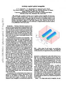
currently working on movable membrane structures for adaptive optics. The second technology is more novel. It is based on silica micromachining. This technology is used when the propagation of light needs to be controlled or modified by a silica structure. The silica structure can be simply an optical element made of silica, for instance a lens, moved by a mechanical structure. Refractive or diffractive microlenses arrays have been fabricated but the best illustration of this technology is a one-dimensional (1-D) microscanner. But a more novel approach is the combination of “silica micromachining” and “integrated optics” technologies, where light is guided by waveguides included in moving mechanical structures. The more advanced devices are 2, 1 4, 1 8) and optical vibration optical switches (1 sensors. It is also possible to combine these two technologies in order to benefit from the optical advantages of silica (wavelength transparency, planar-waveguide fabrication, possibility of passive fiber-chip connection), and the mechanical advantages of silicon (low material stresses, design flexibility, easy electrode fabrication). In the following, three of the following devices have been chosen to illustrate this activity: an optical switch, an optical vibration sensor and a 1-D optical scanner. A. Micromechanical Switches for Optical Networks Today, in optical fiber networks, the state-of-the-art of switching techniques is based on “electronic fabric.” This technique becomes unadapted to an optical network where DWDM is commonly used with bit rates of 2.5–40 Gb/s on each wavelength. Optical–electrical–optical (O-E-O) conversion must be avoided in order to build the “all optical network.” Optical switches and optical cross-connect (OxC) matrixes are key elements of this network. They must offer functions such as protection, restoration, and provisioning. If we consider the dimensions of switching devices, small, medium, and large , switches are mandatory. Small switches (1 2, 2 2, 1 ) will be mainly used for protection and add–drop applications, but they can also be considered as elementary elements to built larger OxC system. Medium and large switches will be OxC systems. The expected dimensions depend used for on the system architecture: from 32 32 to more than 1000 1000 if the system operates at the wavelength level. For small or moderate size switches, some integrated optics solutions, generally based on thermooptical or electrooptical effects, are proposed. Their advantages are mainly low loss and high speed achievable, but they often suffer from wavelength or polarization sensitivity. To overcome these limitations and also to offer very low crosstalk, mechanical solutions have been developed. The proposed mechanical solutions are generally based on moving optical fibers [8], on moving micromirrors arrays for free space switching [7] or on inkjet bubbles technology [19]. Another very attractive approach, proposed by LETI, relies on moving waveguides driven by an electrostatic actuator [20]. This solution exhibits all the advantages of mechanical solutions and solves the problems of power consumption, high switching time, and limited scalability encountered with devices based on moving fibers. The principle of the elementary 1 2 switch (Fig. 5) relies on the mechanical deflection of a cantilever beam bearing an
Fig. 5. Schematic view of the elementary 1 cross-section view).
2
2 switch (top view and
input waveguide thanks to an electrostatic driving structure. A voltage applied between two adjacent electrodes creates an electrostatic force. This force makes the cantilever beam deflect. Consequently, the moving waveguide faces the selected output waveguide and can switch from one to the other. The main advantages of this device is that the switching function is obtained without direct action on the light propagation. The consequence is that wavelength and polarization sensitivities can remain as low as what can be expected with a simple, but well design waveguide. This is a huge advantage for application in optical fiber networks, since it will allow to use this switch not only for -band applications, but also in the extended bands expected on the near future for very high-capacity DWDM systems (S, L, L bands ). Very low crosstalk can also be reached. An additional advantage is the very low power consumption due to the electrostatic driving. Moreover, the combination “mechanical actuation/electrostatic driving” insures a switching time in the order of 1 ms, perfectly in agreement with the requirements. Fig. 6 shows SEM photographies of an improved elementary 1 2 switch. Compared to the basic principle presented before, the metal has been removed from the moving waveguide in order to separate the optical and electromechanical functions. The design of the device is a trade off between low optical loss, low optical crosstalk, and the lowest possible driving voltage. The distance between the output waveguides must be large enough to ensure low crosstalk, but narrow enough to limit the mechanical deflection required. The cantilever beam must be narrow enough to ensure low driving voltage and wide enough to avoid optical losses due the silica/air interface. The electrostatic comb structure, the interelectrodes gap and the beam length must be configured in order to take benefit of the electrostatic instability phenomenon in order to reduce the applied voltage. “Optical” stoppers are implemented to control the switched states. Typical dimensions are the distance between output waveguides 20 , beam length and width 2 mm, 20 CMS length, and width: 500 , 5 .
OLLIER: OPTICAL MEMS DEVICES BASED ON MOVING WAVEGUIDES
Fig. 6. SEM views of an improved elementary 1
Fig. 7. Packaged 1 2 switches.
2
159
2 2 switch.
2 2 and 1 2 8 switches.
Fig. 8.
Key figures for 1
Fig. 9.
Wavelength behavior through 1150–1650-nm range .
2 8 switching module with its three stages of cascaded 1
Based on this approach, 1 switches have also been fabricated simply by cascading elementary 1 2 switches linked together with optical waveguides. Fig. 7 shows a packaged 1 8 switching module. Complete characterization of 1 2 and 1 8 switches have been carried out through the ITU grid (1528–1561 nm). The insertion losses of the silicon chip are below 2.5 dB. Insertion losses include fiber coupling (G652) at both ends and losses due to the silicon chip such as propagation losses and gap losses with remaining misalignments. The wavelength dependence and the polarization-dependent loss (PDL), refering to insertion losses, are very low 0.5 and 0.3 dB, respectively. For both chan45 dB and is not dependent on nels, the optical crosstalk is wavelength ( 3 dB) neither on polarization ( 2 dB). The effective switching time yields 400 s. The optical performances of the switches have been strongly improved by a configuration where index matching gel is introduced in the gap near the beam tips. The insertion losses decrease from 2.5 to 1.5 dB, the wavelength dependence is 0.2 dB and the return loss is 60 dB. Moreover, recent improvements allow to keep the switching time below 1 ms even when index matching oil is used. The good results obtained on 1 2 switches associated with a size reduction and the very accurate and reproducible control of residual deflections allow the fabrication of large 1
switches by cascading 1 2 switches. 1 2, 1 4 and 1 8 switches have been fabricated. Experimental performances 2 and 1 8 switches are collected in Fig. 8. Fig. 9 of 1 highlights that this kind of space switch is not wavelength dependent through a very wide wavelength range (1150–1650 nm investigated). Moreover, a 8 8 all-optical switch has also been demonstrated using arrays of 1 8 switches. It combines a modular 8 scalable Broadcast and select (B&S) architecture and 1 switching modules. A wavelength-division-multiplexing experiment at 16 10 Gb/s has been reported, showing a basic intrinsic capacity of, that is to say the total information traveling in the switch, 1, 28 Tb/s, that can be extended up to 80 wavelengths (6, 4 Tb/s) and even more [21]. This switch can be used for either wavelength, band, and fiber routing.
160
IEEE JOURNAL ON SELECTED TOPICS IN QUANTUM ELECTRONICS, VOL. 8, NO. 1, JANUARY/FEBRUARY 2002
Fig. 10.
Transducer head principle (Si chip).
Fig. 11.
SEM view of the sensitive structure .
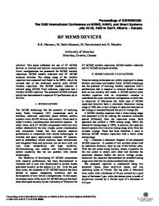
B. Microvibration Sensor for Monitoring of Vibrating Machines A fully integrated optical vibration sensor based on moving waveguide has also been successfully developed by LETI in order to allow the monitoring of rotating machine in harsh electromagnetic environments. To satisfy the requirements for high sensitivity, wide frequency range and insensitivity to the harsh environment (high electromagnetic fields and high temperature), LETI has developed an optomechanical vibration microsensor fully integrated on silicon with a specific optical readout [22]. The device is constituted of the following three elements: a passive optomechanical transducer head, an electronic unit deported far from the electromagnetic fields, and the optical fibers link. The transducer head (Figs. 10 and 11) is made of a mechanical structure and an intensity modulation optical circuit both integrated on the silicon substrate. The mechanical structure is constituted of a moving cantilever beam bearing an input waveguide with a butterfly-like seismic mass that moves under acceleration. The mechanical displacement is detected by an optical circuit that is constituted of a moving input waveguide, a multimode interference (MMI) coupler and two output waveguides. Within the desired acceleration range, the difference of intensity between the two output waveguides is proportional to the acceleration through a wide range of amplitude. The sensitivity
Fig. 12.
Amplitude response (f : 120 Hz).
Fig. 13.
Frequency response (Amplitude: 50 ms
).
has been enhanced by the use of a MMI structure in the optical readout circuit. The main experimental performances are presented in Figs. 12 and 13. The experimental amplitude range lays between 1 and 600 m/s2 with a linearity better than 1% (Fig. 12). The resolution is 0.5 m/s2. The resolution is 0.5 m/s2. The frequency range is 30–2000 Hz with a linearity better than 5% (Fig. 13). The transverse sensitivity, measured in the direction perpendicular to the sensitive direction, is 5% over the entire frequency range. This device shows that MEMS based on moving waveguides can also be considered as an attractive solution for sensors. This is particularly true if the sensor must be used in a harsh electromagnetic environment since it is one of the well-known advantage of optical sensors. Three prototypes have been installed successfully in a Spanish hydroelectric power plant. C. Micro Scanner The device described below is based on the same technology as the optical switch and the optical vibration sensor, but it differs from these devices by the fact that the light is not guided in a waveguide, but only deflected by a moving optical structure. A 1-D scanner has been developed by LETI for obstacle detection applications in automotive application. When dealing
OLLIER: OPTICAL MEMS DEVICES BASED ON MOVING WAVEGUIDES
Fig. 14.
Principle.
Fig. 15.
SEM view of 1-D microscanner.
Fig. 16.
Detailed view of the structure.
161
Fig. 17.
Optical beam deflection versus driving voltage.
an electrostatic comb. As the lenses are displaced laterally relative to each other, the wave plane incident along the optical axis emerges collimated, but tilted from the optical axis. The main advantages exhibited by this solution are the following: broadband wavelength range usable because lenses are made of silica, optical design flexibility which allow to design any aspherical optical diopters profiles in order to optimize the optical behavior of the system, possibility to address fixed locations. A typical working behavior is presented on Fig. 17. Two operating modes are available, out of resonance if the application requires addressing determined positions or at resonance if the application requires larger amplitude angles. As expected, out of resonance, the 10 optical deflection angle corresponds to a mechanical amplitude of 20 m and is reached with a driving voltage of 140 V. At resonance, the deflection angle is higher and the driving voltage lower. The best experimental performance obtained at resonance is 10 for a driving voltage of 12 V. This device demonstrates that silica micromachining can also be used in an effective way not only to move optical waveguides, but also to design other optical elements that can be moved by using actuators made of silica. VI. CONCLUSION
with laser beam deflection devices achieved by means of microtechnologies, most often technologies based on moving integrated micromirrors are proposed, because they can offer the large deflection angles required for some application such as barcode reader for instance. When moderate amplitude is required, which is the case for the automotive application we are talking about, alternative solutions are possible. This innovative solution proposed by LETI is based on cylindrical microlenses shifting [23]. One of its highest interests is to be able to be manufactured with the previously developed and existing technologies developed for the microswitches and vibration sensor. Moreover, the planar configuration of the devices make easier to solve manufacturing and packaging problems. Figs. 14–16 show the optical scanning device structure. It is constituted of two cylindrical lens system in an afocal configuration fabricated in silica layers. One of them is fixed, the second can be moved normally to the optical axis by means of
This presentation highlights the present spectacular growth in MOEMS interest and involvement. In particular it shows that in addition to the well-known technologies based on micromirrors made with silicon micromachining, another technology has been developed and can be very attractive. This technology is based on moving waveguides. A lot of demonstrations are based on silica on silicon technology even if it is not the only possibility. Finally, the examples presented (switches, vibration sensors, scanners) demonstrate that, when solution are found to overcome the specific technological problems, very competitive devices can be fabricated. ACKNOWLEDGMENT The author would like to thank his colleagues from LETI who helped these developments through numerical simulation, mask design, silicon wafers processing, or simply helpful discussions. He also thanks all companies or organizations who supported this work though financial contracts.
162
IEEE JOURNAL ON SELECTED TOPICS IN QUANTUM ELECTRONICS, VOL. 8, NO. 1, JANUARY/FEBRUARY 2002
REFERENCES [1] R. W. Trach, “Opportunities for MEMS in lightwave networks,” in MOEMS 99, Mainz, D, Aug. 30–Sept. 1, 1999. [2] L. J. Hornbeck, “Digital light processing and MEMS: An overview,” in Optical MEMS and Their Applications, Keystone, Aug. 5–9, 1996. [3] T. Weyrauch, M. A. Vorontsov, T. G. Bifano, A. Tuantranont, V. M. Bright, J. Karpinsky, and J. Hammer, “Performance evaluation of micromachined mirror arrays for adaptive optics,” Proc. SPIE, vol. 4124, 2000. [4] P. Tayebati, P. Wang, M. Azimi, L. Maflah, and D. Vakhshoori, “Microelectromechanical tunable filter with stable half symmetric cavity,” Electron. Lett., vol. 34, Oct. 1998. [5] C. Marxer, M. A. Grétillat, N. F. de Rooij, R. Battig, O. Anthamatten, B. Valk, and P. Vogel, “Reflective duplexer based on silicon micromechanics for fiber-optic communication,” J. Lightwave Technol., vol. 17, Jan. 1999. [6] J. A. Walker, K. W. Goossen, and S. C. Arney, “Fabrication of a mechanical antireflection switch for fiber-to-the-home systems,” J. Microelectromechanical Systems, vol. 5, Mar. 1996. [7] L. Y. Lin and E. L. Goldstein, “Optical-layer networking: opportunities for and progress in ligthwave micromachines,” in OFC 2000, Baltimore, MD, Mar. 7–10, 2000. [8] P. Kopka, M. Hoffmann, and E. Voges, “Bistable 2 2 and multistable 1 4 micromechanical fiber-optic switches on silicon,” in MOEMS 99, Mainz, D, Aug. 30–Sept. 1, 1999. [9] C. Marxer, Y. Girardin, and N. F. De Rooij, “4 4 fiber optic matrix switch based on MOEMS,” in MOEMS 99, Mainz, D, Aug. 30–Sept. 1, 1999. [10] C. Wagner, J. Frankenberger, and P. P. Deimel, “Optical pressure sensor based on Mach–Zehnder interferometer integrated with a lateral a-Si : H p–i–n photodiode,” IEEE Photon. Technol. Lett., vol. 5, pp. 1257–1259, Oct. 1993. [11] S. Wu and H. J. Frankena, “Integrated optical sensors using micromechanical bridges and cantilevers,” in SPIE Integrated Optics and Microstructures, vol. 1793, Boston, MA, Sept. 1992. [12] M. Hoffmann and E. Voges, “Thermo-optical digital switches on silicon,” in ECIO 95, Delft, The Netherlands, Apr. 1995, pp. 403–406. [13] E. Ollier, P. Labeye, and F. Revol, “A micro-opto-mechanical switch on integrated optics on silicon,” in ECIO 95, Delft, The Netherlands, Apr. 3–6, 1995. [14] M. Horino, K. Sato, T. Akashi, N. Komatsu, and D. Kobayashi, “Development of prototype micromechanical optical switch,” in JSME Int. J., ser. C, 1998, vol. 41, no. 4. [15] O. Blum Spahn, C. Sullivan, J. Burkhart, C. Tigges, and E. Garcia, “GaAs-based micromechanical waveguide switch,” in Optical MEMS Conf., Kauai, HI, Aug., 22–24 2000.
2
2
2
[16] S. C. Kan, T. T. H. Eng, S. S. Y. Sin, and G. K. L. Wong, “Silicon on insulator (SOI) movable integrated optical waveguide technology,” Sensors and Actuators, vol. A 54, pp. 679–683, 1996. [17] Y.-H. Jin, K.-S. Seo, Y.-H. Cho, S.-S. Lee, K.-C. Song, and J.-U. Bu, “An SOI optical microswitch integrated with silicon waveguides and touch-down micromirror actuators,” in Optical MEMS Conf., Kauai, HI, Aug., 22–24 2000. [18] D. Haronian, “Bottlenecks of opto-MEMS, micro-opto-electro-mechanical systems,” Proc. SPIE, vol. 4075, 2000. [19] J. E. Fouquet, “Compact optical cross-connect switch based on total internal reflection in a fluid-containing planar circuit,” in OFC 2000, Baltimore, MD, Mar. 7–10. [20] E. Ollier, C. Chabrol, T. Enot, P. Brunet-Manquat, J. Margail, and P. Mottier, “1 8 micro-mechanical switches based on moving waveguides for optical fiber network switching,” in Optical MEMS Conf., Kauai, HI, Aug. 21–24, 2000, pp. 39–40. [21] J.-P. Faure, L. Noirie, and E. Ollier, “A 8 8 all optical space-switch based on a novel 8 1 MOEMS switching module,” in OFC 2001, Anaheim, CA, Mar. 19–22. [22] E. Ollier, P. Philippe, C. Chabrol, and P. Mottier, “Micro-opto-mechanical vibration sensor integrated on silicon,” J. Lightwave Technology—Special Section on MOEMS, vol. 14, Jan. 1999. [23] K. Petroz, E. Ollier, H. Grateau, and P. Mottier, “Integrated silica microopto-mechanical steering device for laser beam scanning,” Sensors and Actuators, vol. 73, 1999.
2
2
2
Eric Ollier was born in 1968. He received the degree of physical engineer and the Ph.D. degree in “optics, optoelectronics and microwaves,” both from the National Politechnical Institute of Grenoble (INPG), France, in 1991 and 1995, respectively. During his Ph.D. period, he worked at LETI-CEA, where he has undertaken research into microoptomechanics in order to develop an optical microswitch for optical telecommunications. In 1995, at the end of Ph.D., he joined the Microtechnologies Department at LETI-CEA, Grenoble Cedex 9, France, to be in charge of projects dealing with MOEMS (optomechanical switches, optomechanical vibration sensor, optomechanical scanner) and integrated optics (power splitters, collective, and passive alignment). He is currently working on optical switching and optical cross-connect matrix for optical networks. He holds six patents and has authored and co-authored 23 journal papers and conference contributions.