This full text paper was peer reviewed at the direction of IEEE Communications Society subject matter experts for publication in the IEEE Globecom 2010 proceedings.
Optimal Allocation of Monitoring Trails for Fast SRLG Failure Localization in All-Optical Networks Bin Wu, Pin-Han Ho
János Tapolcai, Peter Babarczi
Dept. of Electrical and Computer Engineering University of Waterloo Waterloo, ON, Canada, N2L 3G1 E-mail:
[email protected],
[email protected]
Dept. of Telecommunications and Media Informatics Budapest University of Technology and Economics Budapest, Hungary E-mail: {tapolcai, babarczi}@tmit.bme.hu
Abstract—We study SRLG (Shared Risk Link Group) failure monitoring and localization in all-optical WDM (Wavelength Division Multiplexing) networks. All links in each SRLG are logically grouped as a whole, and they fail at the same time when the SRLG failure event occurs. To achieve fast SRLG failure localization, monitoring is carried out at the optical layer using the recently proposed monitoring trail (m-trail) structure. By formulating an ILP (Integer Linear Program), we optimally solve the m-trail allocation problem to achieve unambiguous SRLG failure localization with the minimum monitoring cost. We claim that our work provides the first study in optimally allocating freerouted m-trails for achieving fast and unambiguous SRLG failure localization, with flexible tradeoff between the monitor cost and the bandwidth cost (i.e., supervisory wavelength-links).
can detect the on-off status of the supervisory optical signal transmitted in the m-trail. Obviously, if any link traversed by the m-trail (defined as an on-trail link) fails, the supervisory optical signal will be disrupted. Then, the monitor will generate an alarm by observing a Loss of Light (LoL). An m-trail can be routed in the most flexibly manner. It can start or terminate at any node, and take any possible route, as long as it can be feasibly launched with a supervisory optical flow through a sequence of adjacent links. Therefore, an m-trail can traverse a directed link once and a node multiple times. As pointed out in [3], the m-trail concept generalizes all existing monitoring structures at the optical layer, including simple/nonsimple monitoring cycles (m-cycles) [7-9] and arbitrary open trails (such as link-based monitoring trails and non-simple paths with multiple local loops at any node on the m-trail). Several works [3, 5] use m-trails for single link failure localization in WDM networks. In essence, a single m-trail allows its dedicated monitor to simultaneously check the health status of all links on this m-trail, but still cannot localize the particular failed link. By properly allocating a set of m-trails in the network, each link failure will disrupt a unique set of mtrails, and thus produce a unique alarm code to localize the failed link. For single link failure localization, it is summarized in [3] that the m-trail allocation problem can be mapped to a problem of binary coding of each link, subject to the network topology and the m-trail structure constraints. This coding mechanism only needs a few binary bits to produce a sufficient number of distinct alarm codes for unambiguous link failure localization. Since each binary bit in an alarm code matches the on-off status of an m-trail, this approach dramatically cuts down the required number of monitors (compared with the conventional monitoring schemes [10]), and thus greatly simplifies network management by managing only a small set of monitors. It is proved [3-5] that the number of m-trails required to identify a single link failure is lower-bounded by the logarithm of the number of links in the network. Due to the best flexibility and generality of the m-trail structure, the problem of single link failure localization can be gracefully solved based on mtrails [3-5], where the logarithmic relation between the number of m-trails and the network size (in terms of the number of links) is well observed. However, so far we have not found any solid and effective solution for optimally solving the SRLG failure localization problem using m-trails. We notice that SRLG failure localization is studied in [9] using monitoring cycles and paths (which are considered in a subset of m-trails), and a nonadaptive fault diagnosis scheme is proposed in [11] for
Keywords-Failure localization; ILP (Integer Linear Program); monitoring trail (m-trail); Shared Risk Link Group (SRLG).
I.
INTRODUCTION
The fast growth of Internet applications has imposed very stringent bandwidth and QoS (Quality of Service) requirements on communication networks [1]. It pushes Internet backbone networks towards all-optical WDM (Wavelength Division Multiplexing) networks. With WDM technology, hundreds of wavelengths operating at 10 Gb/s or higher rate can be multiplexed onto a single fiber for parallel data transmission. In practical network implementations, generally several fibers are wrapped into a conduit for fiber placement, and a fiber link between two switching nodes may pass through several conduits. If a conduit is disrupted, all fiber links inside will be cut at the same time. Such a set of links sharing a common risk of failure is defined as an SRLG (Shared Risk Link Group) [2]. SRLG failure due to the disruption of the shared resource will lead to failures of all links in the SRLG. This results in huge amount of data loss because of the high-speed nature of alloptical WDM networks. Therefore, it is very important to localize the failure in a timely manner, such that those failed links can be immediately bypassed in order to achieve fast optical recovery of the disrupted traffic. Generally, a monitoring scheme is required to monitor the health status of the network and to localize the failed SRLG. It is preferred that monitoring is carried out at the optical or physical layer, such that signaling efforts can be minimized to render fast failure localization. To this end, we use monitoring trail (m-trail) which is a recently proposed all-optical structure for fast failure localization in WDM networks [3-5]. An m-trail is implemented as a supervisory lightpath with a dedicated monitor equipped at its sink. The monitor [6] is a device which
978-1-4244-5637-6/10/$26.00 ©2010 IEEE
This full text paper was peer reviewed at the direction of IEEE Communications Society subject matter experts for publication in the IEEE Globecom 2010 proceedings.
localization of multiple link failures by launching a set of predetermined optical signals (or probes) in parallel. Though those studies are closely related to ours, in Section II we will show in details that the algorithms provided in [9, 11] are actually heuristics in nature, thereby sacrificing the optimal performance guarantee. Besides, both works [9, 11] ignore the tradeoff between the monitor/probe cost and the bandwidth cost (i.e., supervisory wavelength-links or probing hops). In this paper, we focus on optimal allocation of m-trails for achieving fast and unambiguous SRLG failure localization in all-optical WDM networks. The problem is solved using an ILP which enables a flexible tradeoff between the monitor cost and the bandwidth cost. We claim that this is the first work to optimally solve the SRLG failure localization problem using the optical layer m-trail structures. The rest of the paper is organized as follows. Section II reviews the related works in [9, 11]. Section III formulates the ILP for optimally solving the SRLG failure localization problem. Numerical result is presented in Section IV. We conclude the paper and give some future directions in Section V. II.
LITERATURE REVIEW
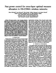
Since [9, 11] are closely related to our work, we review them in more details, and show the differences to our work. The work in [9] focuses on the SRLG failure localization problem using monitoring cycles and paths. A monitoring location is defined as a node which can start or terminate a monitoring cycle or path. The authors in [9] formulate their problem in the following two steps. Step 1 minimizes the number of monitoring locations required for localizing an SRLG failure in a given topology, where all possible SRLGs with up to arbitrary k links are considered. Based on those monitoring locations found, Step 2 adopts either an ILP (Integer Linear Program) or a heuristic to find m-cycles or paths passing through those monitoring locations, such that each SRLG in a given set of SRLGs can be uniquely identified. In specific, this work has studied a special case with a single monitoring location where only m-cycles are considered. For a more general case of multiple monitoring locations in the network, a transformed graph is made by merging all monitoring locations into a single super-node as illustrated in Fig. 1 [9], and thus the problem is equivalently transformed to finding m-cycles in the special case with a single monitoring location. When the graph is transformed back, those m-cycles found in the transformed graph are also mapped to some mcycles or paths in the original network topology. Some issues prevent the work in [9] from achieving optimal solutions as it claims: 1) Step 1 finds monitoring locations for an arbitrary set of SRLGs with up to k links in each. This only depends on the network topology, instead of the set of SRLGs Monitoring location
Super-node ≡ {1, 6}
1
2
5
6
3
4
7
8
3
2
5
4
7
Fig. 1. Merge two monitoring locations {1, 6} into a super-node [9].
8
given to the problem. As a result, the monitoring locations found may not optimally match the specifically given set of SRLGs in Step 2; 2) In Step 1, a node is arbitrarily selected as the monitoring location of a network component [9] (which is a connected subgraph of the network topology possibly consisting of multiple nodes and links). Since there is not a specific way to determine the monitoring location of a component, the approach in [9] fails to yield deterministic performance in the subsequent m-cycle allocation process when choosing a different node as the monitoring location; 3) Since no tradeoff between monitor cost and bandwidth cost is considered in [9], it is not clear how minimizing the number of monitoring locations in Step 1 is related to the optimization objectives in Step 2; and 4) The ILP in Step 2 adopts a cycle enumeration approach, but it is not clearly pointed out in [9] whether simple or non-simple cycles [13] are enumerated. Using only simple cycles leads to a greatly reduced solution space without optimality insurance. On the other hand, ILP based on non-simple cycle enumeration is not practical due to the huge computational complexity [13]. Another work [11] proposes a non-adaptive fault diagnosis scheme based on CGT (Combinatorial Group Testing) [12] to localize multiple link failures. In this scheme, a set of optical signals (or probes) are launched in parallel along a set of predetermined lightpaths to probe the syndromes (or alarms) of a network such that all link failures can be identified. A heuristic is designed which identifies a fault-free subgraph in the network and uses it as a hub to route other necessary probes to diagnose failures. The objective is to minimize the total number of probes, where a probe (with its lightpath) is equivalent to an m-trail in our work. But, those probing lightpaths are routed according to some heuristic rules (e.g., follow some link-disjoint spanning trees [11]). As a result, this heuristic only searches a very limited solution space, where the flexibility of monitoring structures is not fully explored and the logarithm relation (between the number of probes and the network size) is not well pursued. Besides, no tradeoff between the number of probes and the probing hops is considered in [11]. Our work differs from the above studies by achieving optimal design using the most freely routed m-trails, with flexible tradeoff between monitor cost and bandwidth cost. III.
ILP FORMULATION
A. General Idea We assume a single SRLG failure in a given set G={g} of SRLGs, where each SRLG g consists of a set of links sharing a common risk of a single failure event, and all the links in the SRLG fail simultaneously due to the failure event. Let the solution consist of J m-trails {tj |J > j ≥ 0}. We define that an SRLG is passed through by an m-trail tj if tj passes through any link in the SRLG. Thus, the failure of an SRLG disrupts tj if and only if tj passes through the SRLG, which in turn causes the monitor on tj to alarm due to Loss of Light (LoL). Let bj=1 denote the event that the monitor on tj alarms, and bj=0 otherwise. The status of all J m-trails/monitors constitutes a binary alarm code [bJ-1, ..., b1, b0]. To achieve unambiguous SRLG failure localization, this alarm code must be unique for each SRLG g ∈ G. Therefore, the allocation of m-trails must lead to an alarm code [bJ-1, ..., b1, b0] = [bgJ-1, ..., bg1, bg0] against
978-1-4244-5637-6/10/$26.00 ©2010 IEEE
This full text paper was peer reviewed at the direction of IEEE Communications Society subject matter experts for publication in the IEEE Globecom 2010 proceedings.
a failure of SRLG g, where [bgJ-1, ..., bg1, bg0] is a predetermined unique alarm code assigned to SRLG g ∈ G. The paper targets at the scenario of any single SRLG failure identification and localization. Since different SRLGs contain different sets of links, optimal allocation of m-trails is to distinguish this discrepancy and meanwhile minimize the required network resources. In other words, we are going to determine a set of m-trails such that any pair of SRLGs can be unambiguously differentiated. Note that in the scenario considered in this paper, a link could be included in some SRLGs but no any m-trail passes through it. In addition, the failure of an SRLG means the failure of all the links in the SRLG, which may lead to one or multiple link failures on an mtrail tj. Then, the monitor on tj alarms (i.e., bj=1) no matter how many failed links are passed through by tj. Therefore, the problem considered in this paper is fundamentally different from the problem of single link failure localization, where the discrepancy among the set of SRLGs should be identified, instead of considering individual links contained in the SRLGs. On the other hand, the objective of the design is the same as [3-5], which is to minimize the monitoring cost as in (1). Monitoring Cost = monitor cost + bandwidth cost = r × number of monitors + cover length (1) The number of monitors equals to the number of m-trails, and the cover length is the total number of supervisory wavelengthlinks of all m-trails. The cost ratio r gives the relative cost weight of a monitor to a supervisory wavelength-link, which is predetermined based on the particular engineering concerns [35]. By using different values of r in the design, we can achieve a tradeoff between the monitor cost and the bandwidth cost. B. Background Techniques Our ILP for SRLG failure localization is based on some techniques well established in other papers, such as voltage analysis [3] (or Cycle Exclusion [14]). To make this paper selfcontained, we briefly review those techniques in the following. Voltage analysis [3] is to ensure a single valid (connected) m-trail at a time. We use a directed on-trail vector to denote a supervisory wavelength-link. To define an m-trail tj, we can require tj to have a pair of source and sink, and each of other nodes in the network must have an equal number of inbound and outbound on-trail vectors of tj incident on it (i.e., flow conservation [15]). The problem is that, except producing a single connected m-trail, multiple node-disjoint cycles may be generated at the same time. To get a single connected m-trail, those redundant node-disjoint cycles must be excluded. To solve the above problem, we assign a positive voltage value to each on-trail vector of tj, and require the voltage of an outbound vector at each on-trail node to be larger than that of an inbound vector, except at the sink where tj terminates. This is called the voltage constraint. Since there is only a unique sink for tj, those node-disjoint cycles do not pass through the sink. Thus, the voltages along any one of them must always keep increasing, which is impossible due to its cyclic structure. Based on this, all those redundant cycles can be excluded and a single valid m-trail is ensured. It is proved in [3] that if a node is traversed by an m-trail multiple times, the voltage constraint is equivalent to requiring the voltage sum of all outbound vectors at this node to be larger than that of all inbound vectors.
Besides, the work in [3] adopts the following constraints to ensure the inequality of two decimal integers ax and ay (i.e., ax≠ay), where β is a very small positive constant. fxy is a binary where fxy=1 means ax>ay and fxy=0 means ax0). It is the minimum step of voltage increase along an m-trail. β: A predefined small positive constant and 2 J≥β>0. j euv : Binary variable. It takes 1 if u→v is an on-trail vector of m-trail tj, and 0 otherwise. mj: Binary variable. It is 1 if tj is an m-trail, and 0 otherwise. suj : Binary variable. It takes 1 if node u is the source of mtrail tj, and 0 otherwise. duj : Binary variable. It takes 1 if node u is the sink of m-trail tj, and 0 otherwise. j zu : Binary variable. It takes 1 if node u is traversed by m-trail tj, and 0 otherwise. quvj : Non-negative fractional variable. It is the voltage of vector u→v on m-trail tj. It takes 0 if u→v is not an ontrail vector on tj. bgj: Binary variable. It is the jth bit in the predetermined binary alarm code assigned to SRLG g. It takes 1 if m-trail tj passes through at least one link in g, and 0 otherwise. ag: General integer variable. It is the decimal translation of the binary alarm code assigned to SRLG g ∈ G. fxy: Binary variable. For two distinct SRLGs x, y ∈ G, it takes 1 if ax>ay, and 0 if ax