Optimal Operating Ranges of Three Modulation. Methods in Dual Active Bridge Converters. Y. Wang, S. W. H. de Haan and J. A. Ferreira. EEC group, Delft ...
Optimal Operating Ranges of Three Modulation Methods in Dual Active Bridge Converters Y. Wang, S. W. H. de Haan and J. A. Ferreira EEC group, Delft University of Technology, the Netherlands
Abstract- The dual active bridge (DAB) converter attracts more and more attentions thanks to its advantages over the other isolated dc-dc converters, such as soft-switching, immunity to parasitic inductance, less circuit components and less component stress. Rectangular (also named as phase-shifted) modulation method on DAB has been widely studied and but other two proposed modulations (trapezoidal and triangular methods) have much less applications. Due to the characteristics of the modulation principles, one of these three methods outperforms the other two in certain operating ranges from system efficiency point of view. This paper summarizes the properties of three modulation methods and optimizes the combined use of three modulations on a DAB converter (12V/360V, 1 kW and 25 kHz) in order to obtain the best system efficiencies over full converter operating range. A validated loss model is utilized as the analyzing platform, based on which the optimal operating ranges of three modulations are determined.
I.
Lleak
vini
vvoo
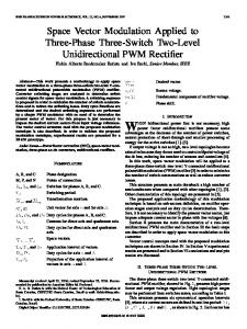
Fig. 1 DAB circuit diagram
9.5 cm
INTRODUCTION
MOSFET modules
The dual active bridge (DAB) converter was first introduced in 80’s [1]. It outperforms the other isolated DC-DC converters by the merit such as soft-switching, immunity to parasitic inductance, less circuit components and less component stress [2]. There are single-phase as well as three-phase dual active bridge converters [3]. This paper will deal exclusively with single-phase DABs. Despite relatively complex modulation scheme to be implemented, DAB attracts more and more attentions due to the emerging sophisticated controller like DSP [4][5][6]. Until now, three main modulation methods are available to be applied on DAB, namely, Rectangular (or named phase-shifted), Trapezoidal and Triangular methods. They have different current shapes and switching patterns [7]. Many papers have been dedicated to the improvement of the soft-switching range of the rectangular modulation method [8][9], however, few publications analyze the other two. The combined usage of trapezoidal and triangular methods in the full operating range is presented in [10]. Because of their own switching patterns and current shape characteristics, each of these three modulation methods has its optimal operating range of Vi, Vo and Load P, in which the resultant system losses is minimum compared with other two. If only rectangular modulation is applied, the system efficiency seriously deteriorates in the range where the ratio Vi / Vo deviates far from the transformer turns ratio 1:N. Combined use of three modulations will drive the efficiencies higher and more
Output bridge
Input bridge
High current winding
Planar core
IGBT module
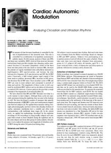
Fig. 2 Photo of the DAB prototype (12V/360V, 1 kW, 25 kHz)
homogeneous over the full DAB operating range. A DAB converter prototype was built for marine application. It will connect the battery on board to the dc bus which powers the 50 Hz inverter. DAB circuit diagram and the photo of the power circuit of the prototype are shown in Fig. 1 and Fig. 2, respectively. This DAB converts the battery voltage 12 V to the 360 V dc, with the high frequency transformer located between input and output switching bridges as the galvanic isolation. The winding turn ratio of the transformer is 1: 30, the switching frequency is 25 kHz and the nominal output power is 1 kW. This paper will comprehensively analyze and compare the characteristics of three modulation methods (section II). Using an experimentally validated loss model (section III) that is able to accurately and rapidly analyze the losses in DAB over the full operating ranges, the optimal operating ranges of three modulations are determined (section IV). II.
THREE MODULATION METHODS
In the DAB converter, the semiconductors in the input and output bridges are modulated in such a way that the both terminal voltages of the transformer vi and vo (see Fig. 1) have square voltage waveforms with a phase delay between each other. The voltage difference between vi and vo stresses on the
����������������������������嘋�����,(((
,3(0&���� 1397
Input voltage source
Llk vin
vo
G
T/2
Vo Vi
Output voltage source
T/2 t
�
vi(t) - vo(t) A
Fig. 3 equivalent circuit of the high frequency transformer
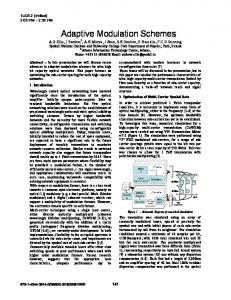
leakage inductance of the transformer Llk, resulting in the winding current. The equivalent electrical circuit of the transformer in DAB is illustrated in Fig. 3. vi and vo could have two (+ and –) or three (+, 0 and –) levels, depending on the modulation methods used. Below introduces the rectangular, trapezoidal and triangular modulations applied to DAB. Rectangular Modulation [1] Under this modulation scheme, the terminal voltages (vi and vo) of the transformer have two levels square waveforms with 50% duty ratio (see Fig. 4). vi is � degree ahead of vo if the energy flows from input to the output. When vi lags behind vo the energy flow reverses. The maximum power transfer capability of DAB with rectangular modulation can be achieved when � = 90o. The difference between vi and vo, the leakage inductance value, and the power level determine the current flowing through the transformer winding, that is, ileak in the bottom graph of Fig. 4. The detailed operating principle can be found in [1]. Here, the turn-on of any semiconductor is initiated while its anti-parallel body diode is conducting. This ensures that the active device naturally takes over as the diode current reverses with almost zero-voltage conditions. Thus, the turn-on losses virtually eliminated. As the current through the active device falls in the turn-off interval, the left current is diverted to the snubber capacitor of the other switch on the same bridge leg, causing its voltage to rise in a resonant manner. If the semiconductors are over-snubbed, the voltage rise across the turned off semiconductor can be small, which can be seen as a ZVS turn-off. It is found in the experiment that the ZVS turn-on loss is negligible but the turn-off is not due to the actually non-zero-voltage condition, so we call this quasi-turn-off. Note that only rectangular modulation method is implemented on the DAB prototype.
B CD
T5,8 off
T5,8 off T1,4 off
T1,4 off
-Vi+Vo Vi-Vo 0
t ileak
� T2,3 off T6,7 off
T6,7 off
Quasi-ZVS turn-off Fig. 4 Voltages and winding current of transformer (Rectangular modulation)
�2
�1 Vo Vi T/2
t
� vi(t) - vo(t)
vi(t) vo(t)
T/2 T5 off
T5 off T4 off �blank
Vi-Vo
T4 off
t ileak
T2 off T7 off
T7 off
Quasi-ZVS turn-off Fig. 5 Voltages and winding current of transformer (Trapezoidal modulation)
�2
�blank
�1
Vo Vi T/2
B.
C.
F
Vi+Vo
A.
Trapezoidal Modulation [7] To decrease the switching losses due to the quasi-turn-off, trapezoidal modulation could be used. Compared with rectangular modulation, trapezoidal modulation forces a zero voltage level in vi and vo by inserting a blanking period �blank, as shown in Fig. 5. Doing this will gain four ZCS turn-off which have nearly zero loss and have four less quasi-turn-off. However, with the presence of the blanking time, trapezoidal modulation has to utilize higher rms current in transformer and semiconductors than the rectangular modulation does to transfer the same amount of power, hence generating higher conduction loss. This is especially obvious when the ratio vi/vo becomes far different from 1: N.
E
vi(t) vo(t)
t
T/2
� vi(t) - vo(t)
vi(t) vo(t)
T5 off
T5 off
Vi -Vi+Vo t Vi-Vo -Vi
ileak T7 off
T7 off
Quasi-ZVS turn-off
Triangular Modulation [7]
Fig. 6 Voltages and winding current of transformer (triangular modulation)
1398
TABLE 1 SUMMARY OF THREE MODULATION METHODS Items
Rec. Mod.
Trapezoidal Modulation
Triangular Modulation
Pmax
S VV i o 8 f sw Llk N
Vi V (1 � 2W blank f sw ) 2 4 Llk f sw ( N 2Vi 2 � N VV i o � Vo )
Vi 2 (1 � 2W blank f sw ) 2 (Vo � N Vi ) 4 LlkVo f sw
Pmin
0
Vi 2 (1 � 2W blank f sw ) 2 (Vo � N Vi ) 4 LlkVo f sw
0
Num. of ZVS and/or ZCS
8
12
14
Num. of quasi-ZVS Toff
8
4
2
rms current in the circuit for
Lowest
the same load Ctrl. Complexity
2
2 o
Medium
Highest
(if within the operating range)
(if within the operating range)
High
High
Low
Triangular modulation is actually a special case of trapezoidal modulation, with one edge of vi and vo overlaps. This causes the shape of the transformer current to be triangular, as illustrated in Fig. 6. Only two qusi-ZVS turn-off are left and the switching loss is further reduced. However, the conduction loss will not be improved thanks to the resultant current peak. To keep the triangular current shape, triangular modulation has a maximum transferred power which turns to be the minimum transferred power of the trapezoidal modulation for holding the trapezoidal current shape. TABLE 1 summarizes the characteristics of above three modulation methods. It can be observed that three modulations have different power ranges, different switching losses and different rms current value to transfer the same power to the output. One modulation must outperform others in certain DAB operating range from loss point of view. To maximize the system efficiency over the entire operating range, the combined use of three modulations is necessary. Optimal operating ranges of three modulations can be determined with a loss model that is able to accurately calculate the losses under different modulations. III.
2
Inputs
Outputs
Operating points
Po ,Vin , Vout Design parameters
Waveform Modeling
Component losses & system losses
Lleak , N sw , f sw Heatsink Temperature
Loss Calculation
Junction temperature of semiconductor
T s in k
Fig. 7 the proposed loss model concept
frequency 25 kHz, therefore the conduction loss in the DAB is significantly larger than the switching loss. To a balance between the modeling accuracy and calculation speed, the on-resistance of the used semiconductors are calibrated as a function of rms current and case temperature, while the quasi-ZVS turn-off is assumed as a resistance switching and the switching times are simply taken from datasheets. The accuracy of this loss model is validated on the DAB prototype [11]. IV.
LOSS MODEL
The basic idea of the proposed loss model (Fig. 7) is to program in MathCAD sheet in such a way that the component losses and system losses could be defined as a function of many variables: operating points (vi, vo and P), designed circuit parameters (e.g. switching frequency fs and leakage inductance of transformer Llk and the count of paralleled switches Nsw) and heatsink temperature Tsk. An index of modulation is set in the loss model for switching among three modulation methods. The outputs of the loss model include the component losses, system losses and even the junction temperature of semiconductors. Basically, there two main steps in the loss modeling: waveforms modeling and loss calculation. All of the input variables to the loss model exert influences on both steps. The details of this loss model can be found in [11]. The DAB prototype has about 100 A rms current at rated condition but is designed with a relatively low switching
Loss Model programmed in MathCAD
OPTIMAL OPERATING RANGES OF THREE MODULATIONS
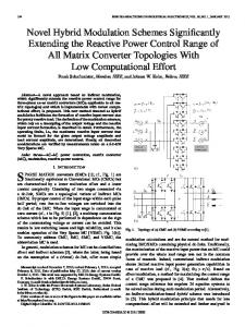
Based on the experimentally validated loss model, the optimization of the DAB prototype design is conducted. Before calculating the optimal operation ranges of three modulations, the DAB prototype is analyzed. Fig. 8 shows the modeled DAB system losses at 1 kW with varied input and output voltages under rectangular modulation method. One can find that when vi /vo close to the transformer turn ratio 1: 30 the system losses stay at low level but it increase dramatically when vi /vo deviates far away from 1:30. This situation should be changed if the losses are supposed to be minimized over the entire operating range. Fig. 9 illustrates the modeled system losses at 1 kW and rated voltage condition, with varied switching frequency fsw and leakage inductance Llk. It can be concluded that smaller fsw and Llk will generate less system losses. Obviously, small fsw restrains the switching loss. The reason why small Llk is
1399
¨ System Loss (W)
Vin (V)
Vo (V)
Vo (V)
Fig. 8 Modeled system losses at 1 kW with varied input and output voltages (rectangular modulation) System Loss (W)
fsw (kHz)
Vin (V)
Fig. 10 Modeled system efficiency with Llk = 125 �F at 1 kW with varied input and output voltages
¨
Lsk (uH)
Vo (V)
Fig. 9 Modeled losses at 1 kW with varied switching frequency and leakage inductance Llk of transformer (Vi/Vo = 12V/360V)
Vin (V)
Fig. 11 Modeled system efficiency with Llk = 70 �F at 1 kW with varied input and output voltages
preferable is that small Llk utilizes lower rms current to transfer the power. However, small leakage inductance deteriorates the system efficiency when vi /vo is far away from turn ratio 1:30. This can be observed by comparing Fig. 10 and Fig. 11, which illustrate the modeled system efficiency with Llk = 125 �F and 70 �F. The efficiency surface with with Llk = 125 �F is flatter than that with with Llk = 70 �F. Until now, we can conclude that smaller leakage inductance will improve the system efficiency but the efficiency will suffer from smaller leakage inductance when the converter voltages deviate far from the rated condition. In order to improve the system efficiencies over a wide voltage ranges with the low leakage inductance, the combined use of three modulations (rectangular, trapezoidal and triangular methods) are evaluated. The loss model is used to compare the system efficiencies with three modulation methods over entire operating range and the one with highest efficiency is selected in the corresponding range. 70 �F leakage inductance is used as the design target. Fig. 12 – 14 plots the modeled system efficiency surface at 1000W, 500 W and 200W over entire DAB converter ranges with three modulation methods implemented at the same time.
The system efficiencies of the modulation method with the lowest losses are identified in the corresponding ranges. Comparing with Fig. 11, we can clearly see that via the combined use of three modulations the efficiency surface is remarkably flatted over the operating range, meanwhile the efficiency still stays at the high level about 93.4% near the rated condition (12V/360V, 1 kW). At the edge of the voltage ranges, the triangular modulation is the most effective control method and maintains the system efficiency above 82 % at 1 kW. When vi /vo is close to turn ratio, the rectangular modulation is still the best at rated load. This is partly because it is a converter with high current but relatively low frequency, which is more sensitive to the conduction loss. If the switching frequency increases, maybe the trapezoidal modulation could be the better option at rated condition due to its lower switching losses and comparable conduction loss. However, at the lower output power, e.g. 500 W and 200 W, the trapezoidal modulation performs better than the rectangular one near the range vi /vo = 30 and triangular modulation works with the maximum efficiency over the rest of the operating These calculated optimal operating ranges of three modulations can be programmed and mapped in the DSP
1400
method in the corresponding range. Further experimental verification will be the future work. ¨ Tr i.
V.
This paper summarizes the properties rectangular, trapezoidal and triangular modulation methods which can be implemented on DAB converter. The performance of DAB prototype with only rectangular modulation method implemented is stated. System performances of DAB with these three modulations are analyzed. It is found that the combined use of these modulations is able to improve the system efficiency over a wide voltage ranges and the optimal operating ranges of three methods are determined based on a validated loss model. The results show that with combined modulations the DAB system efficiencies are maximized over full operating range and the efficiency pattern becomes much flatter than the case only with rectangular modulation applied.
Re c
Tr ap . Tr i. Vin (V)
Vo (V)
CONCLUSIONS
Fig. 12 Modeled system efficiency (Llk = 70 �F) at 1000 W with the combined use of three modulations
REFERENCES [1]
M. H. Kheraluwala, “High power high frequency DC-to-DC converters”, Ph.D. dissertation, University of Wisconsin – Madison, Wisconsin, USA, 1991 [2] M. N. Kheraluwala, R. W. Gascoiqne, D. M. Divan and E. D. Baumann, “Performance characterization of a high-power dual active bridge DC-to-DC converter”, IEEE Trans. Ind. Appl., vol 28, no. 6, pp 1294-1301, Nov./Dec., 1992 [3] R. W. De Doncker, D. M. Divan and M. H. Kheraluwala, “A three-phase soft-switched high power density dc-to-dc converter for high power applications”, IEEE Trans. Ind. Appl. vol. 27, no. 1, pp 63-73, Jan./Feb. 1991. [4] Shigenori Inoue and Hirofumi Akagi, “A bidirectional DC-DC converter for an energy storage system with galvanic isolation”, IEEE Trans. Power Electron., vol. 22, no. 6, pp. 2299-2306, Nov. 2007 [5] H. Tao, A. Kotsopoulos, J. L. Duarte and M. A. M. Hendrix, “Transformer-couple multiport ZVS bidirectional DC-DC converter with wide input range”, IEEE Trans. Power Electron., pp. 771-781, vol. 23, no. 2, Mar. 2008 [6] J.A. Ferreira, I. W. Hofsajer and J. D. van Wyk, “Exploiting the third dimension in power electronics packaging”, in Proc. of IEEE 12th Annu. APEC., Atlanta, USA, vol. 1, pp-419-423, Feb. 23-27, 1997. [7] N. Schibli, “Symmetrical multilevel converters with two quadrant dc-dc feeding,” Ph. D. dissertation, Ecole Polytechnique Federale de Lausanne (EPFL), Suisse, Switzerland, 2000. [8] K. Vangen, T. Melaa, A. K. Adnanes and P. E. Kristiansen, "Dual active bridge converter with large soft-switching range" , in Proc. of 5th European Conference on Power Electron. And Appl., Brighton, UK, vol. 3, pp.328-333, Sep. 13-16, 1993. [9] G. G. Oggier, R. Ledhold, G. O. Garcia, A. R. Oliva, J. C. Balda and F. Barlow, “Extending the ZVS operating range of dual active bridge high-power DC-DC converters”, in Proc. of IEEE 37th Annu. PESC, Jeju, Korea, pp. 1-7, June 18-22, 2006. [10] F. Krismer, S. Round and J. W. Kolar, “Performance optimization of a high current dual active bridge with a wide operating voltage range”, in Proc. of 37th PESC, Jeju, Korea, June 18-22, 2006. [11] Y. Wang, S. W. H. de Haan and J. A. Ferreira, “Methods for experimental assessement of component losses to validate the converter loss model”, in Proc. of 13th EPE-PEMC, pp. 187-194, Sept. 1-3, 2008.
¨ Tr i.
Tr ap . Tr i.
Vin (V)
Vo (V)
Fig. 13 Modeled system efficiency (Llk = 70 �F) at 500 W with the combined use of three modulations
¨ Tr i. Tra p. Tr i.
Vo (V)
Vin (V)
Fig. 14 Modeled system efficiency (Llk = 70 �F) at 200 W with the combined use of three modulations
controller which will select the most effective modulation in the
1401