IEEE TRANSACTIONS ON CIRCUITS AND SYSTEMS—I: REGULAR PAPERS, VOL. 63, NO. 1, JANUARY 2016
1
Phase Noise Reduction and Optimal Operating Conditions for a Pair of Synchronized Oscillators Oriel Shoshani and Steven W. Shaw
Abstract—We investigate the dynamics of a pair of noisy coupled oscillators and derive operating conditions that minimize phase noise. The generic model employed allows for general nonlinear dynamics of the resonant elements of the oscillators, in terms of their amplitude-dependent frequencies, general asymmetric coupling, and both additive and multiplicative noise sources. The model is analyzed using the method of stochastic averaging and the results suggest an optimal operating point for minimizing phase noise in either of the oscillators by varying the operating amplitudes and the nature and strength of the coupling. We also show that the system with asymmetric coupling has the ability to reduce the phase noise of the noisier oscillator beyond the expected result for synchronized oscillators. The analytical predictions, which are validated by Monte-Carlo simulations, show how one can exploit nonlinear behavior to improve phase noise characteristics using a pair of coupled oscillators. The results also point to a means of designing and optimizing larger sets of coupled oscillators to improve phase noise performance. Index Terms—Noisy coupled oscillators, nonlinear AM to PM conversion, phase-noise reduction, stochastic averaging, synchronization.
I. INTRODUCTION
P
HASE-NOISE IS a principal concern in the design of all oscillators used for time-keeping applications. The lack of an absolute time reference is evident in the oscillator output spectrum, specifically, by broadening of the spectral-lines at the oscillator harmonics, and the introduction of high power levels at neighboring frequencies, both of which lead to degradation in frequency precision. The literature on this topic is vast and includes phase noise models [1]–[8], phase noise computation [9]–[16], and methods for phase noise reduction [17]–[23]. While there has been major progress in both theory and applications, continuing demand for low cost, high precision oscillators motivates the consideration of new approaches for the reduction of phase noise. A primary motivation for the present work is the recent development and implementation of M/NEMS-based oscillators that offer favorable system and package integration features
Manuscript received June 06, 2015; revised October 09, 2015; accepted October 16, 2015. Date of publication November 05, 2015; date of current version February 15, 2016. This work was supported in part by Defense Advanced Research Projects Agency (DARPA) through the Dynamic Enabled Frequency Sources (DEFYS) program ( FA8650-13-1-7301) and by US Army Research Office (ARO) ( W911NF-12-1-0235). This paper was recommended by Associate Editor A. Mazzanti. O. Shoshani is with the Department of Mechanical Engineering, Michigan State University, East Lansing, MI 48824 USA (e-mail:
[email protected]. edu). S. W. Shaw is with the Department of Mechanical Engineering and the Department of Physics and Astronomy, Michigan State University, East Lansing, MI 48824 USA (e-mail:
[email protected]). Color versions of one or more of the figures in this paper are available online at http://ieeexplore.ieee.org. Digital Object Identifier 10.1109/TCSI.2015.2495781
when compared to quartz elements, and their frequency stability characteristics are comparable to those of typical quartz oscillators [24], [25]. Moreover, as the size of M/NEMS devices decreases, inherent nonlinearities and noise become more prominent [26]–[28], which leads to degradation of frequency precision due to amplitude-modulation (AM) to phase-modulation (PM) conversion [29]. However, it is possible to resolve this limitation to some extend by operating at a zero-dispersion (ZD) point where the AM to PM conversion is locally eliminated [30], [31]. As shown in Section III-B below, for a noisy oscillator with dominant additive noise, the ZD point is the optimal operation amplitude, providing minimal phase noise. Synchronization of multiple oscillators provides another approach for reducing phase noise, a concept that goes back to Huygens [32]. This idea has been refined in many other applications, for example, the widely used phase-locked loop (PLL) is essentially a voltage-controlled oscillator (VCO) that is synchronized by an input signal to provide a much cleaner output signal than the input with the same nominal frequency (e.g., noises in the amplitude and the high-frequency band are eliminated). Similarly, self-injection lock techniques have been used in lasers to reduce frequency noise [33]. Here part of the oscillator output signal is used to injection lock the oscillator itself, enhancing phase locking (synchronization) for certain stability conditions. The practical significance of phase noise reduction due to synchronization has led to a large number of studies. Kurokawa [34] showed that the phase noise of an oscillator can be considerably improved by synchronization with an external signal while the amplitude noise degrades slightly. Chang et al. [35] showed the phase noise reduction in mutually synchronized oscillators for a case where the amplitude noise and AM to PM conversion are negligible. Mazzanti and Svelto [19] showed that one can control independently both the phase noise and the phase accuracy in a pair of synchronized coupled VCOs that are injection-locked to a master VCO running at twice the output frequency. Deng and Niknejad [36] demonstrated a VCO coupling technique based on 4-port inductors that considerably improved the phase noise performance. Tohidian et al. [37] used the phase noise reduction in order to achieve an ultra-low phase noise in a pair of mutually synchronized high-swing class-C oscillators. Suárez et al. [38] derived an explicit semianalytical relation between the oscillators and the coupling parameters for design optimization. Recent studies have experimentally demonstrated phase noise reduction of two mutually synchronized M/NEMS oscillators [39], [40]. Furthermore, the measurements of Agrawal et al. [39] demonstrate that the point of minimum phase noise (highest frequency stability) is amplitude dependent. We note that in these studies the oscillators have nominally identical
1549-8328 © 2015 IEEE. Personal use is permitted, but republication/redistribution requires IEEE permission. See http://www.ieee.org/publications_standards/publications/rights/index.html for more information.
2
IEEE TRANSACTIONS ON CIRCUITS AND SYSTEMS—I: REGULAR PAPERS, VOL. 63, NO. 1, JANUARY 2016
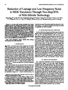
frequencies and reactive coupling. Thus in order to obtain synchronization, the resonators must exhibit amplitude-frequency (AF) dependence [41]. However, for generality, here we consider oscillators with frequency ratio ( integers), and both dissipative and reactive coupling, so that AF dependence is not essential for synchronization. Moreover, in order to keep the analysis general, that is, applicable to electronic, optical, electromechanical, etc., devices, we employ an energy formulation to obtain the governing equations for a generic model that captures the essential physics. Specifically, we employ a Lagrangian description which is commonly used in mechanics [42] but is generally applicable to systems that store, release, and dissipate various forms of energy. The objectives of this paper are as follows: i) to present a consistent derivation of a generic model for the systems of interest, expressed in terms of a stochastic differential equation (SDE) for the phase dynamics of two weakly coupled oscillators with frequency ratio , and wide-sense stationary noise sources; ii) to analyze synchronization scenarios corresponding in the presence to frequency ratios of noise, including a comparison of these cases; iii) to derive conditions for optimal operation in terms of phase noise reduction in the presence and absence of a ZD operating point; and iv) the development of procedures for phase noise cleaning of a noisy oscillator by a cleaner oscillator using asymmetric coupling. The paper is organized as follows: Section II presents a detailed derivation of the simplified Langevin equation (a noisy Adler equation) for the phase difference of two mutually synchronized oscillators, followed by a brief analysis for the coexistence of multiple synchronized solutions. Section III describes the phase noise analysis, including analytical derivations, simulation validation of optimal operating points, and phase noise cleaning due to asymmetric coupling. Section IV summarizes the results of this study and presents potential future work along similar lines. II. PROBLEM FORMULATION The generalized coordinates used in the Lagrangian formulation depend on the nature of the system, for example, they are the modal displacements of the mechanical resonators in closed-loop M/NEMS oscillators, and in circuit oscillators they are the electric charges. Here we consider a pair of closed-loop oscillators with a frequency ratio satisfying , ( prime integers). Fig. 1 shows a schematic block diagram . External inof the system for the specific case of puts are used only to provide initial conditions to initiate oscillations. The resonator elements can be mechanical, electrical, or optical, and have an amplitude dependent frequency captured by conservative cubic and quintic nonlinearities. We assume that the oscillators have small dissipation and are weakly coupled, with both reactive and dissipative coupling, and we formulate the problem using the following normalized kinetic and potential energies expressed in terms of the generalized coordinates
Fig. 1. Schematic block-diagram of the coupled oscillator system. Each resonator is embedded in two feedback loops: one used for creating oscillations in each resonator and the other creates coupling between the oscillators. In the oscillator loop, the signal is strongly amplified (gain ) into a diode limiter (saturation ) in order to ensure constant feedback signal to the resonator. In the in order to coupling loop the signal is amplified (gain ) and phase-shifted control the strength and type (reactive, dissipative) of coupling.
where the oscillators are assumed to have identical conservative nonlinearities and weak reactive coupling . Nonconservative effects are described by the generalized loads (2) where represents the saturated closed-loop feedback input (gains, phase shift, etc., for a specific model, see [39]), is the linear dissipation coefficient which is considfor the systems of interest (i.e., the oserably large cillator frequency is much larger than the quality factor) and assumed to be identical for both oscillators, and are widesense stationary, zero-mean additive and multiplicative noises, respectively, and is the dissipative coupling parameter which is assumed to be small . Note that we consider the reactive and dissipative couplings to be conservative and non-conservative, respectively. However, as illustrated in Fig. 1, these can both be non-conservative and arise from a coupling loop, depending on its phase-shift , specifically, provides reactive coupling and results in dissipative coupling, and for the coupling is both reactive and dissipative. The response is conveniently described using complex amplitudes , ( denotes complex-conjugate). Averaging the Lagrangian and the generalized loads with respect to the fast time scale , where is a reference frequency given by , and writing down the time-averaged Lagrange equations [43], we obtain the slowly-varying complex amplitude equations (3)
(1)
where are written explicitly in Appendix A for frequency ratios . Note that is an artificial parameter introduced in order to emphasize the fact that the effects from coupling and noise are small relative to the
SHOSHANI AND SHAW: PHASE NOISE REDUCTION AND OPTIMAL OPERATING CONDITIONS FOR A PAIR OF SYNCHRONIZED OSCILLATORS
uncoupled deterministic dynamics, so that the system yields a pair of deterministic, uncoupled, self-sustained oscillators. Representing the complex amplitudes in polar form, , we obtain the following evolution equations for the amplitudes and the phase difference
3
which includes deterministic and noise terms, as follows. The term
is the phase drift caused by the internal detuning and the AF dependence, which is given by and . The drift terms resulting from coupling and noise sources are given by
(4) where (11)
(5) and denote the real and imaginary part of , respectively, and the are periodic functions of . Note that , each closed-loop oscillator has a stable limit-cycle for where the steady-state constant amplitude of the limit-cycle is determined from the algebraic equation , which describes the condition for which the loop dynamics sustain the isolated oscillator. Note that the oscillators steady-state constant amplitude is solely determined by the to the linear dissiparatio of the amplifier saturation level tion coefficient . Thus, even for different linear dissipation coefficients we can tune amplifiers saturation level so that will have the same amplitude in both oscillators. A. Phase Dynamics , we assume that the limit-cycles are slightly For perturbed , where HOT denote higherorder terms. From the amplitude components of (4) we obtain the following equation for the dynamics of the amplitude perturbations (6) The solution of (6) yields
(7) In steady-state
this reduces to (see Appendix B)
where is a periodic function of that captures coupling effects and contains the effects of noise sources. In (10) we account for “phase only” effects, i.e., by assuming that the oscillators' amplitudes are slaved to their respective phases and noises, and thus we ignore all coordinates other than those that parameterize the limit cycles. This approach can be mathematically justified by invariant manifold theory (see, e.g., [13], [44], [45]) if the attraction to the limit cycle is strong compared to the noises and coupling. The major advantage of this simplification is that complicated systems of differential equations can be reduced to flows in a much lower-dimensional phase space, namely, in this case an invariant torus having only one dimension per oscillator. Note that if and have opposite signs the system will have a ZD point [30] at the amplitude satisfying . At this ZD point the AM to PM noise conversions are eliminated and the phase noise can be significantly decreased [31], [46]. At the ZD point, the noise term and the periodic restoring effect from (10) reduce to (12) a condition investigated in Section III. B. Simplified Langevin Equation for The Phase Difference Equation (10) can be further simplified when the correlation times of the noises are sufficiently small in comparison to the relaxation time of the system, , or, equivalently, are much larger than if the bandwidth of the original noises those of the generated signals, a condition often satisfied in practice. Under these conditions we can apply the limit theorem [47], [48] and simplify the noise term in (10) to yield
(8) which captures the effects of coupling and noise . Consequently, the amplitudes of the coupled oscillators can be approximated by (9) Note that the amplitudes dynamics are solely dependent on the and the noise sources . Substituting phases dynamics the steady-state amplitudes given in (9) into the phase (difference) component of (4) and expanding the result with respect to yields an expression for the phase drift, given by (10)
(13)
4
IEEE TRANSACTIONS ON CIRCUITS AND SYSTEMS—I: REGULAR PAPERS, VOL. 63, NO. 1, JANUARY 2016
where can be regarded as independent zero-mean delta-correlated Gaussian noises of unit intensity. The coefficients in (13), are functions of the power-spectral densities and cross-spectral densities of the original noises and are given explicitly in Appendix C. Note that at the ZD point the first two terms in (13) vanish and it reduces to
(19) Thus, for each case the reactive and dissipative coupling pacan be tuned such that , so that (18) rameters reduces to the following (20)
(14) which immediately reveals that for optimal noise reduction, the ZD point should be located at the highest amplitude possible in order to suppress the effects of additive noise sources , that is, . The ZD point is quantitatively similar to the case when the resonator element in the loop is linear [49], in the sense that the system frequency is independent of amplitude, thus eliminating the conversion of AM to PM. Returning to the general case, we substitute the result in (13) into (10) and set to obtain the following approximated Langevin equation for the phase difference (15) with the modified detuning parameter
which is the well-known noisy Adler equation [50] that appears in many applications, including overdamped Josephson junctions [51], the theory of charge density waves, [52], ditheredring-laser gyroscopes [53], and vortex diffusion in layered superconductors [54]. Note that when , we obtain a similar noisy Adler equation for the biased phase difference where . Also note that (20) is a single scalar SDE which governs the dynamics of interest. In order to obtain the phase dynamics of the individual oscillators (i.e., ) we need to add an additional , so that with the equation for the phase sum equations for and we can determine the dynamics of and . Nevertheless, as shown in Section III-A, the equation for the phase sum is completely determined by the phase difference and does not add any independent information. C. Deterministic Synchronized Solutions
(16) and the simplified zero-mean delta-correlated white noise
(17) Note that is an artificial book-keeping parameter that we introduce in order to emphasize that the coupling and noises are relatively weak. Thus, setting in the analysis is valid as long as the unscaled coupling parameters and noise intensities are small. For the cases of interest, that is, for , and with reactive and dissipative coupling, as expressed in (1) and (2), (15) takes the form (18) where
, (20) is the deIn the absence of random excitation terministic evolution equation for the phase difference of the two weakly-coupled self-sustained oscillators with frequency ratio , a problem that has been extensively studied. Here we provide a brief review of known results, since this provides the deterministic operating points to which the effects of noise are added. For the system has a pair of fixed points (stable and unstable) which correspond to phaselocked/synchronized solutions [41]. Furthermore, for the deterministic model we can construct the following stroboscopic Poincaré map [55] (e.g., with the sampling time ) which is defined on the circle (21) Note that this iterated map (i.e., the sine circle map) is one of the basic models of nonlinear dynamics and the description of (21) for the parameters is well-known [56]–[58]. The domains of synchronized solutions in the plane are confined by the so-called Arnold tongues which are obtained by solving the equation where and are prime integers. Fig. 2 shows the first few Arnold tongues for the case of and reveals that the system possesses synchronized solutions with frequency ratios 1/2, 1/3, 2/3, that is, even when both oscillators have the same nominal frequency higher order synchronization can occur due to the presence of sub- and super-harmonics that arise from the nonlinearities. However, as can be expected, the 1/1 synchronization is the most robust with the widest Arnold tongue and the 1/3, 2/3 are less robust and have Arnold tongues with identical widths. Of
SHOSHANI AND SHAW: PHASE NOISE REDUCTION AND OPTIMAL OPERATING CONDITIONS FOR A PAIR OF SYNCHRONIZED OSCILLATORS
5
TABLE I ESTIMATION OF MAXIMAL NOISE INTENSITY
Fig. 2. Arnold tongues (stability boundaries) of the synchronized responses; .
A. Phase Diffusion for the Oscillators As stated in Section II-B, the determination of requires that we include an equation for the phase sum . Correspondingly, the oscillators phases are given by , . Repeating the analysis applied to in (15), we derive the following Langevin equation for Fig. 3. Rate for the averaged phase difference in the presence of noise for and: (red), (green), (black), (blue), (dashed line).
(22) where
course, higher order resonances are possible, but not of interest here. III. PHASE NOISE ANALYSIS The noisy Adler equation (20), has an analytical solution [47] and can be interpreted as a random walk of a point mass in an inclined (for ) wavy potential. We consider effective noise of intensity modeled by where is proportional to the spectra values of the non-white addiin Appendix C) tive noises at the fundamental frequency ( and the non-white multiplicative noises at the second harmonic and at zero ( in Appendix C). Fig. 3 shows the time derivafor different levels tive of the averaged phase difference of , which reveals that for sufficiently small values of the ratio of noise intensity to coupling, specifically, , the noise has a negligible effect on the region of synchronization. However, for larger ratios, e.g., , the noise completely eliminates the synchronization region and the time derivative of the averaged phase difference is linearly varying with the frequency mismatch, resulting in continual phase drift. We note that this synchronized solution in the presence of noise (which is achieved for ) is the key phenomenon that enables phase noise reduction. Thus, for known values of the coupling parameters for a given system, we can estimate the range of noise intensities over which the system will be synchronized, and the range of frequency mismatch . Table I shows the values for the maximum estimated normalized noise intensities for three coupled oscillators considered in the literature. Note that the systems of Chang et al. [35] and Sancho et al. [9] consist of coupled field-effect transistor (FET)-based oscillators operating at the X-band and the C-band, respectively, with dissipative coupling only , whereas the system of Maffezzoni [59] consists of coupled Colpitts oscillators operating in the VHF-band with reactive coupling only .
(23) Note that (22) shows that the dynamics do not have any stabilizing restoring forces (i.e., unlike (20) where we have , there is no such term in the RHS of (22) for the variable ). Thus, for the case of low ratio of noise intensity to coupling and small frequency mismatch , where the phase difference remains constant for all practical purposes, the effective noise acting on the phase difference has negligible effect on the individual phases . In contrast, the effective noise acting on the phase sum is dominant, that is, the diffusion in (22) is much stronger relative to that in (20), (where , ) and it essentially governs the frequency can stability. Thus, the diffusion constants of the phases be approximated by (24)
6
IEEE TRANSACTIONS ON CIRCUITS AND SYSTEMS—I: REGULAR PAPERS, VOL. 63, NO. 1, JANUARY 2016
By linearizing (20) and (22) about the stable fixed phase difference of the deterministic model , and assuming , we find that the deviation of the phase difference will tend to zero and the deviation of the phase sum will be given by
, at this point we can effectively cancel the AM to PM conversions, resulting in , and reduces to
(25)
In order to suppress the direct interaction of the additive noises with the phases, we would need to consider oscillators with large such that operating amplitudes at the ZD point are small; this is a standard method of improving the SNR. Note that the direct interaction of the multiplicative noises with the are unaffected by the existence of phases given by terms the ZD point. However, due to synchronization we can reduce the proportionality constant in at (24) in order to suppress the multiplicative noises as well. The existence and location of the ZD point are determined by the nonlinear potential coefficients of the oscillator and we can vary and obin (1). Thus, by varying tain the reduced diffusion constant of (29) at different operating amplitudes (e.g., these can be achieved by varying the bias value of a biased Duffing oscillator [31]). The locus of coincide with the diffusion constant of a linear oscillator (i.e., for each pair of fixed there is a fixed , and at the diffusion constant reduces to the diffusion constant of the linear oscillator due the elimination of the AM to PM conversion. Thus, the diffusion constant of all these different pairs of evaluated at their different fixed values of will coincide with the diffusion constant of a linear oscillator). Fig. 4 shows a comparison of the diffusion constants for four different oscillators as a function of am, , and plitude for the case . We examine how tuning the potential parameters results in different cases in terms of the relative positions of the ZD and optimal operating points. In Fig. 4 the linear oscillator case is included for comparison, shown as the blue curve, and the values of the diffusion constants at the ZD points for are denoted by squares. We note that when the ZD point is at a low amplitude, e.g., for , is not minimized at the ZD point, but oc, yielding curs at . For moderate amplitudes, e.g., , and coincide and produce the same diffusion constant. At larger amplitudes, e.g., , two minima occur, one at , which is a local minimum, and the other at , which is a global minimum for these parameters. Note that in all cases, the ZD point tracks the linear oscillator case, even at amplitudes beyond the validity of the linear model. Also note that the linear model represents cases where amplitude perturbation effects are neglected (e.g., [35]) and hence there is no AM to PM conversion. While theoretically the mutually synchronized oscillators with a ZD point at large amplitude seem to be the best option in terms of reducing phase noise, in practice we can find different optimal operation points depending on the case being considered, as follows: i) In the case where the additive noises are weak and the condition can be realized at relatively low amplitude, we find the following: For , operating at either of these points will result in the same phase noise reduction, as depicted in Fig. 5(a),
Consequently, the single-sided spectra of the oscillators phase , can be directly approximated from noise, denoted by the phase sum spectrum, as follows
(26) and is given by (28) where we analyze the contribution of its individual terms. Note that, if both oscillators have the same noise intensity when they are uncoupled, we obtain (27) yields the well known ( which for the case of is the number of oscillators) phase noise reduction [35]. However, when , this symmetry breaks, , and the first oscillator, with diffusion , will always have a (e.g., 1/8 for phase-noise reduction better than ), while the second oscillator, with diffusion , will always have phase-noise reduction less than or, in some cases, it can experience phase noise amplification, e.g., 9/8 for . Thus, the asymmetric synchronization, , provides a platform to clean the low-frequency oscillator phase with the high-frequency oscillator phase. It should be noted that this asymmetric phase-noise reduction is a direct result of frequency ratio scaling since, if we convert the first (low-frequency) oscillator signal to a signal with the frequency of the second oscillator, the resulting phase, , will have the same diffusion constant of the second phase, namely . An alternative, and more efficient, approach to clean one oscillator with the other using asymmetric coupling is presented in Section III-C. For the case of coupled oscillators with different individual noise intensities, it has been shown that a cleaning effect can occur even if the oscillators are not synchronized [60]. B. Optimal Operation Points In the previous subsection we showed that . Thus, in order to obtain low phase noise (high frequency stability) we need to minimize as given by
(28) In order to minimize the phase noise we consider the individual terms in (28) and their physical sources. The first two terms of this expression are due to AM to PM conversions while the remaining four terms result directly from the effects of the additive noises and multiplicative noises . Thus, as discussed in Section II-A, if the oscillators have a ZD point
(29)
SHOSHANI AND SHAW: PHASE NOISE REDUCTION AND OPTIMAL OPERATING CONDITIONS FOR A PAIR OF SYNCHRONIZED OSCILLATORS
7
whereas for , results in a lower diffusion constant, as shown in Fig. 5(b). ii) In the case where the additive noises are not weak, we find the following: For , produces a lower diffusion constant, as seen in Fig. 5(c), whereas for , produces a lower diffusion constant, as shown in Fig. 5(d). C. Asymmetric Coupling We consider for simplicity two oscillators without AF dependence, that is, , and asymmetric dissipative coupling . In this case, the reactive coupling has no effect due to the lack of AF dependence. The approximate Langevin equations for the phase difference and phase sum in this case are given by
Fig. 4. Diffusion constant of the phases, , as a function of the amplitude for and different ZD points: (black), (red), (green), linear oscillator (blue). The values of and are denoted by squares and circles, respectively.
(30) where
(31) Hence, it is seen again that for a low ratio of noise intensity to coupling, , and small frequency mismatch, , the oscillators synchronize with constant phase difference, and as a result . Consequently, we obtain the following approximation for the diffusion constants of the oscillators' phases
(32) Again the scaling holds, as in (24), which is a direct effect of the frequency ratio and leads to the same phenomenon of phase noise reduction amplification discussed in Section III-A with regard to (27). However, there are also effects from the asymmetric coupling, , which per. This effect enables one to sist even in the case of clean a noisy oscillator with a cleaner oscillator without any degradation of the cleaner oscillator and, more interestingly, to obtain some improvement of the clean oscillator as well. However, as we show next, this cleaning effect is insignificant if there is a large difference in the noise intensities of the uncoupled oscillators. In order to show this effect we set , , at (31), (32) and obtain (33) which is in agreement with results in [41], [61]. From (33) we see that for the case where is of better quality, i.e., , we need to tune the coupling such that the influence of
Fig. 5. Location of (black circle) and : (a) , (b) noises: , (d) . noises: (c)
(red square) for weak additive and non-weak additive
Fig. 6. Normalized minimal diffusion constant as a function of the of the isolated oscillators. diffusion constant ratio
will be dominant, that is, , and vice versa for the opposite case. Considering the first case ( is of better quality), we substitute in (33) and obtain (34) which has a minimum at
that yields (35)
Thus, as shown in Fig. 6, the minimal diffusion constant of both oscillators, , is always lower than the diffusion constant of the clean oscillator and approaches as , hence recovering well-known behavior for injection-locking.
8
IEEE TRANSACTIONS ON CIRCUITS AND SYSTEMS—I: REGULAR PAPERS, VOL. 63, NO. 1, JANUARY 2016
Fig. 7. Numerically simulated phase noise for synchronized (red, set 1) and unsynchronized (black, same parameters as set 1 except the coupling is set to zero) response of a noisy oscillator with asymmetric coupling; the inset shows a zoom-in near 1 (kHz) to show fine scale details.
D. Simulations In order to validate the analytical predictions we present results from numerical simulations. The model used consists of a pair of van der Pol oscillators with generalized nonlinearities and coupling, subjected to uncorrelated white noises, as follows
Fig. 8. Phase noise at 1 (kHz) offset from the fundamental harmonic for synchronized oscillators: sets 2 (blue) and 3 (black) are for weak additive noises and , respectively, and sets 4 (red) and 5 (green) with and , respecare for non-weak additive noises with tively. Analytical predictions are shown as solid lines. Results from simulations , , . are shown for TABLE II PARAMETERS VALUES FOR NUMERICAL SIMULATION
(36)
(37) (38) Note that for small dissipation , , the uncoupled and amdeterministic oscillators oscillate with frequencies plitude due to self-excitation. Also, (36), (37) are equivalent to the governing equations one obtains from (1), (2), except that in (36), (37) the oscillation amplitude is limited by nonlinear dissipation rather than by amplifier saturation. There are a large number of efficient and accurate numerical methods to solve these SDEs and calculate the phase noise. These include high order stochastic Runge-Kutta methods for Monte Carlo approaches [62] and perturbation projection vector (PPV) methods for non-Monte Carlo approaches [13]. However, for simplicity we used a standard Euler-Maruyama method to numerically solve the SDEs [63]. In order to assess convergence and stability we performed simulations with three different time steps (mesh refinement), . The averages converged to within for the largest time step, for the smaller two. and to within Figs. 7, 8 show the spectrum of the oscillators' phase noise, , resulting from direct simulations. The system parameters for the cases considered are given in Table II. In Fig. 7 we demonstrate the cleaning effect due to asymmetric coupling which corresponds to set 1 in Table II. The phase noise of the noisy oscillator (oscillator 2) is dramatically decreased when the oscillators are coupled. As the theoretical model predicts, the noisy oscillator phase noise become identical to the phase noise of the cleaner oscillator (oscillator 1). Note that for all the simulations with the different paramters sets in Table II, we observed 20 (dBc/dec) slope in for frequency offset from the fundamental harmonic of . Thus, in what follows we show only at 1 (kHz)
offset from the fundamental harmonic which is a key figure of merit for these operation frequencies [40]. In Fig. 8 we show the phase noise of the synchronized oscillators at 1 (kHz) offset from the fundamental harmonic as a function of the oscillators amplitude . We consider four different sets of parameters, namely, sets 2 ( , , ) and 3 ( , , ) in , Table II for weak additive noises and sets 4 ( , ) and 5 ( , , ) in Table II for non-weak additive noises and calculate their corresponding phase noise analytically (via (26)) and numerically. Note that in all cases considered we found good quantitative agreement between the numerical calculations and the analytical predictions. For the weak additive noises cases we see that in set 2 the phase noise at and at are nearly identical, while for set . Moreover, at a lower am3 lower phase noise is achieved at plitude, here taken as , the phase noise is significantly higher. For the cases of non-weak additive noise we see that the phase noise at is lower than that at for set 4, and the phase noise at is lower than at for set 5. We note that these results also qualitatively agree with theory, as shown in Figs. 5(a), (b) for weak additive noises and in Figs. 5(c), (d) for non-weak additive noises.
SHOSHANI AND SHAW: PHASE NOISE REDUCTION AND OPTIMAL OPERATING CONDITIONS FOR A PAIR OF SYNCHRONIZED OSCILLATORS
E. Summary of Main Results for a pair of a weakly The phase diffusion constants coupled nonlinear oscillators were analytically calculated for both symmetric and asymmetric coupling in different synchronization regimes . For the case of symmetrically coupled oscillators of the same quality (i.e., with the same noise intensity when they are uncoupled), it is shown that when there is a phase-noise reduction in the presence of synchronization even when the AM to PM conversion is taken into account, which extends the analytical result of [35]. For , the oscillator with the lower frequency will always have a phase-noise reduction better than , while the oscillator with higher frequency will always have phase-noise reduction less than , and in some cases it can experience phase-noise amplification. This phase-noise reduction amplification for is a direct result of frequency ratio scaling. In the case of asymmetrically coupled oscillators, the phase diffusion constants scale not only by the frequency ratio parameters , but also by the asymmetric coupling parameters . This extra design freedom allows one to calibrate the coupling parameter ratio in order to obtain a minimal phase diffusion constants; for the case this yields and , where are the noise intensities of the uncoupled oscillators and is the minimal phase diffusion constant in the coupled case. Therefore, for asymmetric coupling one can obtain a phase diffusion constant that is lower than both (i.e., ) and hence exploit this asymmetry in order to clean the oscillators. Note that for , and which reduces to the standard case of symmetric coupling. We also analyzed the effects of a ZD point in a nonlinear oscillators which essentially eliminates the AM to PM conversion and hence locally reproduces the phase diffusion of a linear oscillator. This phase-noise reduction at the ZD point is most pronounced for systems with non-weak additive noise and operating at a large amplitude ZD point. Note that these analytical predictions are applicable only to systems that can be effectively synchronized in the presence of noise, which can be achieved only for sufficiently small values of the ratio of noise intensity to coupling. We estimated an upper bound for this noise intensity for several practical systems with known coupling parameters; see Table I.
9
iments using oscillators based on tunable MEMS resonators are being planned to support the main conclusions of this investigation. APPENDIX A
(39) where
is the saturation level of the amplitude limiter , assuming that the feedback is strongly amplified. The coupling terms for the different frequency ratios are given by (40)
(41)
(42)
(43) APPENDIX B Introducing the new dummy variable obtain
in (7) we
IV. CLOSING REMARKS We derived and investigated models for the phase noise of a pair of coupled self-sustained oscillators. The case of weak coupling allowed us to reduce the problem to a pair of SDEs governing the phase dynamics of the two mutually synchronized oscillators. The corresponding Langevin equations for the phase sum and difference are shown to have optimal operation points for phase-noise reduction of an individual oscillator, along with the theoretical interesting result of cleaning a noisy oscillator with a cleaner one by applying asymmetric coupling. These analytical predictions are validated by numerical simulations and they provide useful insights into methods for reducing phase noise in the presence of mutual synchronization. In future work the analysis will be generalized to arrays of larger scale, which leads to significantly larger phase noise reduction. Also, exper-
(44) For , the first term in RHS of (44) is zero and the second term can be written as (using integration by parts)
10
IEEE TRANSACTIONS ON CIRCUITS AND SYSTEMS—I: REGULAR PAPERS, VOL. 63, NO. 1, JANUARY 2016
REFERENCES
(45) where at the steady-state, only the first term in the RHS of (45) is non-zero. Note that the integrals in (45) contain an increasing exponential in time which yield in principle non-zero terms. However, due to the integration, these terms are multiplied by and hence to leading order of approximation are negligible. APPENDIX C Coefficients of the simplified noise terms
(46)
[1] A. Bonfanti, F. Pepe, C. Samori, and A. L. Lacaita, “Flicker noise up-conversion due to harmonic distortion in van der pol cmos oscillators,” IEEE Trans. Circuits Syst. I, Reg. Papers, vol. 59, no. 7, pp. 1418–1430, 2012. [2] D. B. Leeson, “A simple model of feedback oscillator noise spectrum,” in Proc. IEEE, 1966, pp. 329–330. [3] B. Razavi, “A study of phase noise in cmos oscillators,” IEEE J. SolidState Circuits, vol. 31, no. 3, pp. 331–343, 1996. [4] A. Hajimiri and T. H. Lee, “A general theory of phase noise in electrical oscillators,” IEEE J. Solid-State Circuits, vol. 33, no. 2, pp. 179–194, 1998. [5] J. Rael and A. A. Abidi, “Physical processes of phase noise in differential lc oscillators,” in Proc. IEEE 2000 Custom Integr. Circuits Conf. (CICC), pp. 569–572, IEEE. [6] A. J. Scholten, L. F. Tiemeijer, R. van Langevelde, R. J. Havens, A. T. Zegers-van Duijnhoven, and V. C. Venezia, “Noise modeling for rf cmos circuit simulation,” IEEE Trans. Electron Devices, vol. 50, no. 3, pp. 618–632, 2003. [7] D. K. Agrawal and A. A. Seshia, “An analytical formulation for phase noise in mems oscillators,” IEEE Trans. Ultrason., Ferroelectr., Freq. Control, vol. 61, no. 12, pp. 1938–1952, 2014. [8] M. Bonnin and F. Corinto, “Influence of noise on the phase and amplitude of second-order oscillators,” IEEE Trans. Circuits Syst. II, Exp. Briefs, vol. 61, no. 3, pp. 158–162, 2014. [9] S. Sancho, A. Suárez, and F. Ramirez, “Phase and amplitude noise analysis in microwave oscillators using nodal harmonic balance,” IEEE Trans. Microw. Theory Tech., vol. 55, no. 7, pp. 1568–1583, 2007. [10] D. Murphy, J. J. Rael, and A. Abidi et al., “Phase noise in lc oscillators: A phasor-based analysis of a general result and of loaded,” IEEE Trans. Circuits Syst. I, Reg. Papers, vol. 57, no. 6, pp. 1187–1203, 2010. [11] A. Bevilacqua and P. Andreani, “An analysis of noise to phase noise conversion in cmos harmonic oscillators,” IEEE Trans. Circuits Syst. I, Reg. Papers, vol. 59, no. 5, pp. 938–945, 2012. [12] B. De Smedt and G. Gielen, “Accurate simulation of phase noise in oscillators,” in Proc. 23rd Eur. Solid-State Circuits Conf. (ESSCIRC'97), 1997, pp. 208–211, IEEE. [13] A. Demir, A. Mehrotra, and J. Roychowdhury, “Phase noise in oscillators: A unifying theory and numerical methods for characterization,” IEEE Trans. Circuits Syst. I, Fundam. Theory Appl., vol. 47, no. 5, pp. 655–674, 2000. [14] F. Bizzarri, A. Brambilla, and G. S. Gajani, “Steady state computation and noise analysis of analog mixed signal circuits,” IEEE Trans. Circuits Syst. I, Reg. Papers, vol. 59, no. 3, pp. 541–554, 2012. [15] M. Bonnin and F. Corinto, “Phase noise and noise induced frequency shift in stochastic nonlinear oscillators,” IEEE Trans. Circuits Syst. I, Reg. Papers, vol. 60, no. 8, pp. 2104–2115, 2013. [16] M. Bonnin, “Amplitude and phase dynamics of noisy oscillators” 2015, arXiv preprint arXiv:1503.06603. [17] A. J. Benedick, J. G. Fujimoto, and F. X. Kärtner, “Optical flywheels with attosecond jitter,” Nature Photon., vol. 6, no. 2, pp. 97–100, 2012. [18] A. Mazzanti and P. Andreani, “Class-c harmonic cmos vcos, with a general result on phase noise,” IEEE J. Solid-State Circuits, vol. 43, no. 12, pp. 2716–2729, 2008. [19] A. Mazzanti and F. Svelto, “A 1. 8-ghz injection-locked quadrature cmos vco with low phase noise and high phase accuracy,” IEEE Trans. Circuits Syst. I, Reg. Papers, vol. 53, no. 3, pp. 554–560, 2006. [20] P. Andreani, X. Wang, L. Vandi, and A. Fard, “A study of phase noise in colpitts and lc-tank cmos oscillators,” IEEE J. Solid-State Circuits, vol. 40, no. 5, pp. 1107–1118, 2005. [21] Y.-T. Lee, J.-S. Lim, J.-S. Park, D. Ahn, and S. Nam, “A novel phase noise reduction technique in oscillators using defected ground structure,” IEEE Microw. Wireless Compon. Lett., vol. 12, no. 2, pp. 39–41, 2002. [22] D. Eliyahu, D. Seidel, and L. Maleki, “Rf amplitude and phase-noise reduction of an optical link and an opto-electronic oscillator,” IEEE Trans. Microw. Theory Tech., vol. 56, no. 2, pp. 449–456, 2008. [23] D. T. Chang, H. P. Moyer, R. G. Nagele, R. L. Kubena, R. J. Joyce, D. J. Kirby, P. D. Brewer, H. D. Nguyen, and F. P. Stratton, “Nonlinear uhf quartz mems oscillator with phase noise reduction,” in Proc. IEEE 26th Int. Conf. Micro Electro Mech. Syst. (MEMS), 2013, pp. 781–784, IEEE. [24] R. Henry and D. Kenny, “Comparative analysis of mems, programmable, synthesized frequency control devices versus traditional quartz based devices,” in Proc. IEEE Int. Freq. Control Symp., 2008, pp. 396–401.
SHOSHANI AND SHAW: PHASE NOISE REDUCTION AND OPTIMAL OPERATING CONDITIONS FOR A PAIR OF SYNCHRONIZED OSCILLATORS
[25] J. Van Beek and R. Puers, “A review of mems oscillators for frequency reference and timing applications,” J. Micromech. Microeng., vol. 22, no. 1, p. 013001, 2012. [26] A. N. Cleland, “Thermomechanical noise limits on parametric sensing with nanomechanical resonators,” New J. Phys., vol. 7, no. 1, p. 235, 2005. [27] M. V. Requa and K. L. Turner, “Electromechanically driven and sensed parametric resonance in silicon microcantilevers,” Appl. Phys. Lett., vol. 88, no. 26, p. 263508, 2006. [28] J. F. Rhoads, S. W. Shaw, and K. L. Turner, “Nonlinear dynamics and its applications in micro-and nanoresonators,” J. Dyn. Syst., Meas., Control, vol. 132, no. 3, p. 034001, 2010. [29] S. Levantino, C. Samori, A. Zanchi, and A. L. Lacaita, “Am-to-pm conversion in varactor-tuned oscillators,” IEEE Trans. Circuits Syst. II, Analog Digit. Signal Process., vol. 49, no. 7, pp. 509–513, 2002. [30] M. Dykman, R. Mannella, P. V. McClintock, S. Soskin, and N. Stocks, “Noise-induced narrowing of peaks in the power spectra of underdamped nonlinear oscillators,” Phys. Rev. A, vol. 42, no. 12, p. 7041, 1990. [31] N. J. Miller, “Noise in nonlinear micro-resonators,” Ph.D. dissertation, Michigan State Univ., East Lansing, MI, USA, 2012. [32] C. Huygens, Christiaan Huygens' the Pendulum Clock, or, Geometrical Demonstrations Concerning the Motion of Pendula as Applied to Clocks. Ames, IA, USA: Iowa State Press, 1986. [33] H. Li and N. Abraham, “Analysis of the noise spectra of a laser diode with optical feedback from a high-finesse resonator,” IEEE J. Quantum Electron., vol. 25, no. 8, pp. 1782–1793, 1989. [34] K. Kurokawa, “Noise in synchronized oscillators,” IEEE Trans. Microw. Theory Tech., vol. MTT-16, no. 4, pp. 234–240, 1968. [35] H.-C. Chang, X. Cao, U. K. Mishra, and R. A. York, “Phase noise in coupled oscillators: Theory and experiment,” IEEE Trans. Microw. Theory Tech., vol. 45, no. 5, pp. 604–615, 1997. [36] Z. Deng and A. M. Niknejad, “A 4-port-inductor-based vco coupling method for phase noise reduction,” IEEE J. Solid-State Circuits, vol. 46, no. 8, pp. 1772–1781, 2011. [37] M. Tohidian, S. A. R. A. Mehr, and R. Bogdan, “Dual-core high-swing class-c oscillator with ultra-low phase noise,” in Proc. IEEE Radio Freq. Integr. Circuits Symp. (RFIC), 2013, pp. 243–246. [38] A. Suárez, F. Ramírez, and S. Sancho, “Stability and noise analysis of coupled-oscillator systems,” IEEE Trans. Microw. Theory Tech., vol. 59, no. 4, pp. 1032–1046, 2011. [39] D. K. Agrawal, J. Woodhouse, and A. A. Seshia, “Observation of locked phase dynamics and enhanced frequency stability in synchronized micromechanical oscillators,” Phys. Rev. Lett., vol. 111, no. 8, p. 084101, 2013. [40] M. H. Matheny, M. Grau, L. G. Villanueva, R. B. Karabalin, M. Cross, and M. L. Roukes, “Phase synchronization of two anharmonic nanomechanical oscillators,” Phys. Rev. Lett., vol. 112, no. 1, p. 014101, 2014. [41] A. Pikovsky, M. Rosenblum, and J. Kurths, Synchronization: A Universal Concept in Nonlinear Sciences. Cambridge, U.K.: Cambridge Univ. Press, 2001. [42] H. Goldstein, Classical Mechanics. Chennai, India: Pearson Education India, 1957. [43] A. H. Nayfeh, Nonlinear Interactions: Analytical, Computational, Experimental Methods. Hoboken, NJ, USA: Wiley, 2000. [44] N. Fenichel, “Persistence and smoothness of invariant manifolds for flows,” Indiana Univ. Math. J, vol. 21, no. 193-226, p. 1972, 1971. [45] E. N. Brown, J. Moehlis, and P. Holmes, “On the phase reduction and response dynamics of neural oscillator populations,” Neural Comput., vol. 16, no. 4, pp. 673–715, 2004. [46] J. Moehlis, “Improving the precision of noisy oscillators,” Physica D: Nonlinear Phenomena, vol. 272, pp. 8–17, 2014. [47] R. L. Stratonovich, Topics in the Theory of Random Noise. Boca Raton, FL, USA: CRC, 1967, vol. 2. [48] R. Khas'minskii, “A limit theorem for the solutions of differential equations with random right-hand sides,” Theory Probab. Its Appl., vol. 11, no. 3, pp. 390–406, 1966. [49] T. H. Lee and A. Hajimiri, “Oscillator phase noise: A tutorial,” IEEE J. Solid-State Circuits, , vol. 35, no. 3, pp. 326–336, 2000. [50] R. Adler, “A study of locking phenomena in oscillators,” Proc. IRE, vol. 34, no. 6, pp. 351–357, 1946. [51] A. Barone and G. Paterno, Physics and Applications of the Josephson Effect. New York: Wiley, 1982, vol. 1.
11
[52] G. Grüner, A. Zawadowski, and P. Chaikin, “Nonlinear conductivity and noise due to charge-density-wave depinning in nb se 3,” Phys. Rev. Lett., vol. 46, no. 7, p. 511, 1981. [53] W. Schleich, C.-S. Cha, and J. Cresser, “Quantum noise in a ditheredring-laser gyroscope,” Phys. Rev. A, vol. 29, no. 1, p. 230, 1984. [54] B. Chen and J. Dong, “Thermally assisted vortex diffusion in layered high-t c superconductors,” Phys. Rev. B, vol. 44, no. 18, p. 10206, 1991. [55] J. Guckenheimer and P. Holmes, Nonlinear Oscillations, Dynamical Systems, Bifurcations of Vector Fields. New York: Springer, 1983, vol. 42. [56] V. I. Arnol'd, Geometrical Methods in the Theory of Ordinary Differential Equations. New York: Springer, 2012, vol. 250. [57] V. I. Arnol'd, “Small denominators. i. mapping the circle onto itself,” Izvestiya Rossiiskoi Akademii Nauk. Seriya Matematicheskaya, vol. 25, no. 1, pp. 21–86, 1961. [58] A. Katok and B. Hasselblatt, Introduction to the Modern Theory of Dynamical Systems. Cambridge, U.K.: Cambridge Univ. Press, 1997, vol. 54. [59] P. Maffezzoni, “Synchronization analysis of two weakly coupled oscillators through a ppv macromodel,” IEEE Trans. Circuits Syst. I, Reg. Papers, vol. 57, no. 3, pp. 654–663, 2010. [60] C. Ly and G. B. Ermentrout, “Coupling regularizes individual units in noisy populations,” Phys. Rev. E, vol. 81, no. 1, p. 011911, 2010. [61] A. N. Malakhov, Fluctuations in Self-Oscillatory Systems. Moscow, USSR: Nauka, 1968. [62] K. Burrage and P. M. Burrage, “High strong order explicit runge-kutta methods for stochastic ordinary differential equations,” Appl. Numer. Math., vol. 22, no. 1, pp. 81–101, 1996. [63] D. J. Higham, “An algorithmic introduction to numerical simulation of stochastic differential equations,” SIAM Rev., vol. 43, no. 3, pp. 525–546, 2001.
Oriel Shoshani received the B.S. degree in mechanical engineering from Ben-Gurion University of the Negev, Beer-Sheva, Israel, in 2008 and the Ph.D. degree (direct program) in mechanical engineering from Technion-Israel Institute of Technology, Haifa, Israel, in 2014. Currently, he is a Postdoctoral Fellow in the Department of Mechanical Engineering at Michigan State University, East Lansing, MI, USA. His current research interests include dynamics of fluctuating nonlinear vibrational systems and applications to micro/nano-electro-mechanical systems. Dr. Shoshani’s awards and honors include the Sherman fellowship for graduate studies achievements (2009), Irwin and Joan Jacobs Fellowship for excellence in studies (2011, 2013) and Pnueli prize for Ph.D. thesis (2015).
Steven W. Shaw received the A.B. degree in physics from the University of Michigan, Flint, MI, USA, in 1978, the M.S.E. degree in applied mechanics from the University of Michigan, Ann Arbor, MI, USA, in 1979, and the Ph.D. degree in theoretical and applied mechanics from Cornell University, Ithaca, NY, USA, in 1983. He is currently University Distinguished Professor in the Department of Mechanical Engineering and Adjunct Professor in the Department of Physics and Astronomy at Michigan State University, East Lansing, MI, USA. He has held visiting appointments at Cornell University, the University of Michigan, Caltech, the University of Minnesota, the University of California-Santa Barbara, and McGill University. He currently serves as an Associate Editor for two journals, Nonlinear Dynamics and the SIAM Journal on Applied Dynamical Systems. His research interests are in applied dynamical systems and currently include modeling, analysis, and design of micro-scale resonators for sensing and signal processing applications and nonlinear vibration absorbers for automotive applications. Prof. Shaw is a Member and Fellow of the ASME and recipient of the SAE Arch T. Colwell Merit Award, the Henry Ford Customer Satisfaction Award, the ASME Henry Hess Award, and the ASME N. O. Myklestad Award.