Proceedings of the 1996 IEEE International Conference on Control Applications Dearborn, MI September 15-18,1996
MA02 1O:OO
OPTIMAL SETPOINT CONTROLLER FOR A GENERIC X-29A AIRCRAFT WITH FOREBODY VORTEX NOZZLES John Valasek Department of Mechanical and Aeronautical Engineering Western Michigan University, Kalamzoo, Michigan 49008-5065
[email protected] com df k r
ABSTRACT This paper presents the design, synthesis, and performance of an optimal setpoint high angle-of-attack lateralldirectional controller for the X-29A aircraft equipped with forebody vortex flow control nozzles. The closed-loop control law is full state feedback, and is synthesized using a linear time-invariant generic model of the X-29A. Results demonstrate that by proper selection of the weighting elements, the forebody vortex nozzles together with the aerodynamic control effectors can be modulated to improve the closed-loop response compared to a controller design which uses only the aerodynamic control effectors.
sf stf 1
INTRODUCTION The deployment of lethal, reliable, all-aspect, short range missiles such as the AIM-9X series into the modern air combat arena has diminished the emphasis on sustained maneuvering capabilities [ 11. These "point-and-shoot'' weapons have prompted interest in controlled flight at angles-of-attack well beyond that for maximum lift. Poststall maneuvering in the low-speed, high angle-of-attack portion of the flight envelope, popularly referred to as agility, is motivated by this weapon technology [ 2 ] . Lan indicates in [3] that the agility of fighter type aircraft at high angles-of-attack can be seriously degraded because of the following factors :
NOMENCLATURE H M m n P PSf (r r
V VFC a
P 6
h
n @ It
altitude feet Mach number number of continuous control variables number of state variables number of bang-bang variables, also perturbed body axis roll rate degreeslsecond pounds per square feet dynamic pressure pounds/feet2 perturbed body axis yaw rate degreeslsecond velocity feetlsecond vortex flow control angle-of-attack degrees sideslip angle degrees deflection degrees eigenvalue sub-matrix of inverted quad-partition matrix bank angle degrees set of real numbers
1. 2. 3.
4.
unstable pitch break ineffective propulsionlairframe integration loss of static and dynamic lateral-directional stability reduced control effectiveness
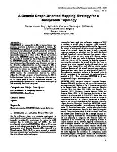
Items 3 and 4 above are of primary concern in this paper. Roll and yaw control effectiveness of fighter configurations typically decreases with increasing angle of attack due to separated flow and spanwise flow on swept wings, asymmetric vortex shedding, or adverse interference from stalled wing flow. The effects can be somewhat countered and lateral agility improved by carefully "tuning" the distribution of available control powers and their rates [4]. Tangential slot blowing using VFC nozzles, a type of bang-bang control effector, for controlling the forebody vortex on fighter type aircraft at high angles of attack (Figure 1) is generally well understood [5-81. A version of the X-29A aircraft fitted with compressed nitrogen gas fed pneumatic VFC nozzles mounted on each side of the forebody, was used to study methods to reduce the loss of directional control power at high angles of attack [l 11.
SuperscriDts e time derivative * trim state transpose of matrix or vector -1 inverse of square matrix Subscripts bb bang-bang effector C canard
0-7803-2975-9/96/$5.00 0 1996 IEEE
commanded value differential flap value at k th sample time rudder symmetric flap strake flap trim value
1
No VFC
where @ is an n by n discrete state transition matrix. The discrete control effectiveness matrices r and Tbb are functions of the integration stepsize 11, and correspond to the continuous and bang-bang effectors respectively. The state vector is Xk E R" , and the control vector containing . The control vector only continuous effectors is Uk E containing only bang-bang effectors is u b b E that:
Right jet acfive
Figure 1 Creation of Forces Using Forebody Vortices in a Vortex Flow Control System [9] A controller for the continuous effectors can be synthesized using the sampled-data regulator (SDR) and its associated weighting matrices [15]. The SDR cost function to be minimized is
As tested in flight, this system proved extremely effective for augmenting directional control power at high angles-ofattack [9]. However, the VFC nozzles were controlled manually by the pilot. During one test flight an earlier than planned manual initiation of the left VFC nozzle caused the X-29A to depart from controlled flight to the left at the start of a planned right roll maneuver [9]. Adams et al. in [ l l ] synthesized a closed-loop VFC controller for the VISTA F-16 by designing a switching surface and implementing a deadband. Another approach is to use the methodology of the author [12, 131, applied to a high angle-of-attack lateral/directional regulator for a generic X-29A type aircraft fitted with VFC nozzles was demonstrated [14]. This paper extends those results by synthesizing an optimal setpoint controller for commanding changes in aircraft attitude.
4,
is an n by n positive semi-definite state where weighting matrix, kkis an ni by ni positive definite control weighting matrix, and Mk is an n by ti1 positive semidefinite matrix which weighs the product of states and controls. This cost function and its weighting matrices are used to obtain the optimal constant feedback gains
SYSTEMS WITH MIXED CONTINUOUS AND BANG-BANG CONTROL EFFECTORS
where P i s the Ricatti matrix. Note that the SDR is not required to design the feedback gains in the present method; any technique can be used provided the gains are stabilizing. The benefit of using the SDR technique is the systematic progression from one candidate controller design to another. The feedback loop is closed with the control law
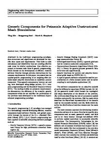
Figure 2 shows a block diagram for a generic system of this type. In [I21 a design methodology is developed for directly designing variable structure controllers for this type of system. This methodology makes it possible to tradeoff system response, continuous effector activity, and bang-bang effector activity.
which accounts for the continuous effectors only. The closed-loop difference equation then has the form
with the vector u b b given by equation (2). To control the bang-bang effectors, it is noted that at every sample interval, the discrete controller can conceivably choose between one of three mutually exclusive control strategies:
Control System with Continuous and Bang-Bang Control Effectors [131
Figure 2 Generic
Consider a controllable and observable sampled-data control system consisting of a continuous plant, and a discrete controller which uses continuous effectors and bang-bang effectors, e.g. iorebody vortex nozzles, as controls. For the linear time-invariant (LTI) case the state difference equation is
2
1.
continuous effector active, bang-bang effector active in the positive position
2.
continuous effector active, bang-bang effector inactive
3.
continuous effector active, bang-bang effector active in the negative position
Strategies one and three above represent a continuous effector with a bang-bang effector included for an extra increment of control power. Normally this occurs for systems or in applications where the bang-bang effector possesses equal or greater control power than the continuous effector. Another consideration is that the bang-bang effector might be a finite resource to be conserved as much as possible. The pneumatic jets on the X-29A which are fueled with stored gas are an example.
where c and D are state and control output matrices respectively, from some specified initial condition yo to a steady-state commanded value ym subject to the state constraint equation (1). The optimal setpoint requires that the control policy U, be optimal according to the cost function (3). Error states
BANG-BANG SWITCHING LOGIC The switching times for the bang-bang effector are determined by generating future system trajectories before the control is updated, using on-line simulation with the bang-bang effector in each of the (+), (o), and (-) states (Figure 3). The candidate structure which generates the lowest cost (state deviation and control activity) in terms of a performance index *
A
are defined where X* and U* are the new trim states, such that at the commanded condition X = X* and U = U*. Substituting the error states into the state equation (1) results in the new state equation %k+l
@(h)%k
+
r(h)Gk
(10)
where
. A
Jk = X k Q x k + U k R U, + 2 X k M U k
(7)
whose weighting matrices are selected by the designer, is selected and used during the upcoming sample interval. The operation of the continuous effector is unaffected. The on-line simulation can use either a full set of nonlinear dynamic equations or d reduced-order linear approximation. In the generic X-29A design examples which follow, a full set of linearized IateraVdirectional equations of motion are used.
by definition because it is a steady-state condition. At this new steady-state condition the output equation (8) becomes
The control law that minimizes the error state form of the cost function (3) is:
Substituting (9) into (13) provides the desired relation for the optimal setpoint control law: initial conditions
To determine X* and U* the steady-state equations are collected and written in augmented state vector form
Figure 3 Sub-Interval Evaluation and Control Selection Scheme [13] Stability and robustness properties of this variable structure controller are presented in [12, 141. Robustness investigations demonstrated that the closed-loop VFC controller is reasonably robust (maximum 15.5%difference i n cost) with respect to large parameter variations in yawing moment due to sideslip angle (Nb), even without sideslip angle feedback.
where the index on X* and U* has been dropped because they are constants. The matrix on the left is the quad partition matrix (QPM). Assuming the QPM is invertible, its inverse is defined as
OPTMAL SETPOINT CONTROLLER
so that U* and X* can be solved for The nonzero setpoint (NZSP) problem is to
determine the control policy Uk that will drive an output
The lateral/directional controller for this illustration uses a 10 Hz sampling rate, which is 20 times faster than the fastest frequency in the lateral/directional model. The simulation model incorporates actuator models reduced from the real X-29A actuators in [16]. A conservative time constant of 0.125 seconds for the VFC nozzles produces a variation in total cost of only 4% compared to a no-lag nozzle, and is used in the examples. The design specifications are:
where (18)
The optimal setpoint control law is therefore
commanded sideslip angle initial sideslip angle 5% settling time in sideslip angle maximum body axis yaw rate maximum bank angle
GENERIC X-29A VFC DESIGN EXAMPLE The objective is to design a closed-loop VFC controller that will drive the system from a specified initial sideslip angle to a commanded terminal nonzero sideslip angle, using the extended NZSP structure. All states are assumed to be fed back (including sideslip angle) and perfectly measurable. A high angle-of-attack trimmed flight condition, where the control power of the VFC nozzles is comparable to that of the differential flap and rudder, is selected for the design example:
The plant model is the generic X-29A LTI lateral/directional model fitted with VFC nozzles, in the normal digital up-and-away (ND-UA) mode 1161. The static margin is -18.23%. The lateralldirectional linear state equation for the generic X-29A at this flight condition is:
)
=
.043
.64
-.77
.073
P
-8.39
.78
-.69
-.74E-5
.063 -.11
-.17E-5
P r
0.
0.
.14 b
Q l l = lo00 Q33 = 200 RI, = 85.
.
1.
0.
.84
QZ2= 900 4 4 4 = 3.65 R22 = 2.5
These weights result in closed-loop eigenvalues = 0.68 ? 1.94j, $ = -3.08j, h4 = -0.13. The closed-loop ,,2.05 ~ Dutch roll frequency and damping ratio are (i~= radlsec, LDR = 0.33, and the closed-loop roll and spiral modes have time constants of 2, = 0.33 seconds and 2, = 7.55 seconds respectively. For clarity the weights and therefore gains are held fixed for each candidate controller design. The only parameter varied is R33 , the weight on the VFC nozzles.
r
b
degrees degrees seconds deglsec 10 degrees
A sideslip angle initial condition of five degrees is sufficiently large enough at this flight condition to excite the Dutch roll and saturate the differential flaps and rudder, but prevent the aircraft from departing controlled flight [ 141. The fuel supply of the VFC nozzles is considered to be finite, so a controller which satisfies the specifications with the least amount of bang-bang activity is desired. Initial elements of the state and control weighting matrices are selected using the relations in [ 171. Using systematic iterations the following weights were selected to generate a nominal controller design:
H1 = 38000. feet V1 = 338 feetkec 6, = -24.4" a, = 20.7"
Mi = 0.35 C X ~ = 40" = 37 psf 6stf = 12.8O
-1.5 5 5 20
CONTROLLER DESIGN
+
-.0034
.0013
.86
-.I7
.092
-.12 0.
0.
[y]
The nominal controller is generated by selecting a sufficiently large initial value of R33 to ensure that the VFC nozzles are not activated. A value of R33 = 1 serves this purpose. Figure 4 shows a lightly damped response i n sideslip angle, with the differential flap and rudder on their rate and position limits for the first six seconds. 'This design just satisfies the maximum bank angle specification but not the settling time specification. The total cost over the duration of the 10 second run is 264.9. The weight on the forebody nozzles is reduced to 0.02 to generate Design 2 (Figure 5). The cost of Design 2 is 207.1, a reduction in cost of 22%. Compared to Design 1 the sideslip angle response is well damped and satisfies the settling time requirement. The duty cycle of
I
where all angular quantities are i n radians. The inodei has three 1ateraVdirectional control effectors: two continuous (differential flaps and rudder), and one bang-bang (VFC nozzles). The open-loop eigenvalues are 3L1,2 = 0.42 f 2.32j, = -0.069 k 0.12j, h, = 0. The unstable openloop Dutch roll frequency and damping ratio are CO,,~ = 2.36 radlsec, CDR = -0.18, and the open-loop lateral phugoid with frequency 0 = 0.14 radlsec, and damping ratio 6 = 0.49 replaces the roll mode and spiral mode.
4
the forebody nozzles are being modulated to supply the additional required yaw control power. However, wear and tear on the differential flap and rudder are being traded for wear and tear on the valves of the forebody nozzles. This is a design tradeoff.
[7] Guyton, Robert W., Osborn, Russell F., and LeMay, Scott P., "Forebody Vortex Control Aeromechanics," AGARD-CP-497, Maneuvering Aerodynamics, Nov. 1991, pp. 16-1 to 16-14. [8] Ericsson, L.E., "Control of Forebody Flow Asymmetry
A Critical Review," AIAA-90-283342.
SUMMARY AND CONCLUSIONS
[9] Hancock, Regis, and Fullerton, Gordon, "X-29 Vortex Flow Control Tests," 1992 Report To The Aerospace Profession, Thirty-Sixth Symposium Proceedings, Beverly Hills, CA, Sept. 1992, pp. 209-219.
A design procedure for the synthesis of variable structure optimal setpoint control laws is demonstrated for an aircraft fitted with a combination of aerodynamic and forebody vortex flow control effectors. Based upon the results of this work it is concluded that:
1.
The extended optimal setpoint controller is effective in properly utilizing the control power of the forebody vortex nozzles for changing vehicle orientations at high angles-of-attack.
2.
The methodology permits the designer to select the activity level of the forebody vortex nozzles, which permits directly trading-off use of the forebody vortex nozzles, the conventional aerodynamic effectors, and closed-loop system performance.
[lo] Walchli, Lawrence A., Guyton, Robert W., Luria, Frank, and Gillard, William J., "High Angle-Of-Attack Control Enhancement On A Forward Swept Wing Aircraft," AIAA-92-4427-CP. [ 1I] Adams, Richard J., Buffington, James M., and Banda, Siva S., "Active Vortex Flow Control for VISTA F-16 Envelope Expansion," AIAA-94-368 1-CP.
[I21 Valasek, John, "Unified Design of Controllers for Systems with Continuous and Bang-Bang Control Effectors," PhD Dissertation, Department of Aerospace Engineering, University of Kansas, Lawrence, KS, April 1995.
REFERENCES
1131 Valasek, John, and Downing, D.R., "A Unified Controller Design Methodology for Systems with Continuous and Bang-Bang Control Effectors," ACC95AIAA-060.
[l] Valasek, John, and Downing, David R., "An Investigation of Fighter Aircraft Agility," NASA-CR194608, Nov. 1993.
[2] Liefer, Randall K., Valasek, John, Eggold, David P., and Downing, David R., "Fighter Agility Metrics, Research and Test," A I M JournaE of Aircraft, Vol. 29, No. 3, MayJune 1992, pp. 452-457.
[ 141 Valasek, John, and Downing, D.R., "A Closed-Loop Forebody Vortex Flow Controller for a Generic X-29A Aircraft," AIAA-95-3248-CP.
[3] Lan, C. Edward, Applied Airfoil and Wing Theory, Cheng Chung Book Company, Ltd., Taipei, Taiwan, Republic of China, 1988, p. 459.
[ 151 Dorato, Peter, et al, "Optimal Linear Regulators: The Discrete-Time Case," IEEE Transactions on Automatic Control, Volume AC-16, Number 6, Dec 1971, pp. 613620.
[4]Eggold, David P., Valasek, John, and Downing, David R., "Measurement and Improvement of the Lateral Agility of the F-18," AIAA Journal of Aircraft, Vol. 30, No. 6, Nov.-Dec. 1993, pp. $03-804.
[ 161 Bosworth, John T., "Linearized Aerodynamic and
Control Law Models of the X-29A Airplane and Comparison With Flight Data," NASA Memorandum 4356, February 1992, p. 16.
[5] Malcolm, Gerald N., and Ng, T. Terry, "Aerodynamic Control of Fighter Aircraft by Manipulation of Forebody Vortices," AGARD-CP-497, Maneuvering Aerodynamics, NOV.1991, pp. 15-1 to 15-22.
Technical
[17] Bryson, Arthur E., Jr. and Ho, Yu-Chi, Applied Optimal Control, Optimization, Estimation, and Control,Hemisphere Publishing Company, New York, NY 1975, pg. 149.
[6] Celik, Zeki Z., and Roberts, Leonard, "Vortical Flow Control on a Wing-Body Combination Using Tangential Blowing," AIAA-92-4430-CP.
5
40 c
40,
:
I
m-..7 r : .........................................................
:
:
m
-40
time (sec)
Figure 4 Design 1, R33= 1, Generic X-29A, 0.35/40k, cost = 264.9
6
Figure 5 Design 2, R33= 0.02, Generic X-29A, 0.35/40k, cost = 207.1
I
t