Aug 11, 1996 - Ya-Dong Gui ... tions on a 64-node SP-1 show that the proposed algorithm signi ... In a mesh or hypercube network, each processor node.
Optimal Software Multicast in Wormhole-Routed Multistage Networks� Hong Xu
Ya-Dong Gui
Lionel M. Ni
Cisco Systems Inc. Institute of Computing Technology Dept. of Computer Science 170 W. Tasman Chinese Academy of Sciences Michigan State University Jan Jose, CA 95134 Beijing, China East Lansing, MI 48824
August 11, 1996 Abstract
Multistage interconnection networks are a popular class of interconnection architecture for constructing scalable parallel computers (SPCs). The focus of this paper is on the multistage network system which supports wormhole routed turnaround routing. Existing machines characterized by such a system model include the IBM SP-1 and SP-2, TMC CM-5, and Meiko CS-2. E�cient collective communication among processor nodes is critical to the performance of SPCs. A system-level multicast service, in which the same message is delivered from a source node to an arbitrary number of destination nodes, is fundamental in supporting collective communication primitives including the application-level broadcast, reduction, and barrier synchronization. This paper addresses how to e�ciently implement multicast services in wormhole-routed multistage networks, in the absence of hardware multicast support, by exploiting the properties of the turnaround switching technology. An optimal multicast algorithm is proposed. The results of implementations on a 64-node SP-1 show that the proposed algorithm signi cantly outperforms the application-level broadcast primitives provided by currently existing collective communication libraries including the public domain MPI.
� This work was supported in part by NSF grants CDA-9121641 and MIP-9204066, and DOE grant DE-FG0293ER25167.
1 Introduction Multistage interconnection networks are a popular class of interconnection architecture for constructing scalable parallel computers (SPCs), such as the BBN TC-2000 [1], IBM SP-1 [2], and NEC Cenju-3 [3]. In such systems, processor nodes are interconnected through multistage networks. Each processor node has its own processor, local memory, and other supporting devices. As the number of nodes in the system increases, the total communication bandwidth, memory bandwidth, and processing capability of the system scales up as well. E�cient data communication among processor nodes is critical to the performance of messagebased SPCs. Generally data communication can be classi ed into point-to-point communication and collective communication [4]. While point-to-point communication deals with the basic send and receive operations between two nodes, collective communication deals with communication that involves a group of nodes. Multiple collective communication groups 1 may space-share a SPC in a way that processor nodes in the system can be partitioned into several disjoint subsets each of which is dedicated to a distinct group. As a result, a system-level multicast service, in which the same message is delivered from a source node to an arbitrary number of destination nodes, is fundamental in supporting collective communication primitives including the application-level broadcast, reduction, and barrier synchronization [5, 6]. However, most existing message-based SPCs support only unicast communication, singledestination message passing, in hardware. In these environments, multicast must be implemented in software by sending unicast messages. One way to implement multicast in such systems is separate addressing in which a separate copy of the message is sent from the source to every destination. As the number of destinations increases, separate addressing may require excessive time because many systems allow a local processor to send only one or a few messages at a time. An alternative approach is a multicast tree in which the source sends the message to only a subset of the destinations. Each recipient of the message forwards it to some subset of the destinations that have not yet received it. The focus of this paper is on multicast tree implementation, also known as unicast-based or software multicast implementation. Issues of software multicast implementation in direct (point-to-point) networks have been addressed in [7]. In [7], an optimal unicast-based multicast algorithm is developed for direct networks 1 A collective communication group refers to the set of nodes which participate in a particular collective communication.
1
characterized by multi-dimensional mesh topology and one-port communication architecture which restricts a processor node to send/receive one message to/from the network at a time. Unlike one-port communication, all-port communication allows each processor node to send/receive one message per communication port at a time. In a mesh or hypercube network, each processor node connects to the network through n ports, where n is the number of neighboring nodes in the network. Several algorithms [8, 9, 10] have been proposed for e�cient unicast-based implementation of collective communication services in direct networks which support all-port communication. Among them, an optimal unicast-based broadcast algorithm [10] is achieved for hypercube networks. Unlike previous work, this paper addresses more e�cient software implementation of multicast services in wormhole routed multistage networks. By exploiting the turnaround switching technology that allows any intermediate switch in a multistage network to route a message back to the side where the message comes from, an optimal software multicast algorithm is proposed for multistage interconnection networks supporting one-port communication. Signi cant performance improvement has been attained by the proposed algorithm against the currently existing collective communication libraries including the public domain MPI [11]. The remainder of the paper is organized as follows. Section 2 describes the system model under consideration which includes switch architecture, network topology, switching techniques, and the number of communication ports. Section 3 presents a deadlock-free routing algorithm for unicast communication. Section 4 de nes the problem addressed in terms of the system model and the unicast routing algorithm. Section 5 presents an optimal software multicast algorithm for turnaround wormhole-routed multistage networks. The results of performance comparison with other collective communication libraries on a 64-node IBM SP-1 are given in Section 6. Section 7 concludes the paper and mentions several areas of future research.
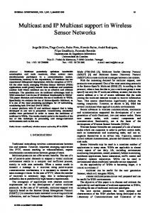
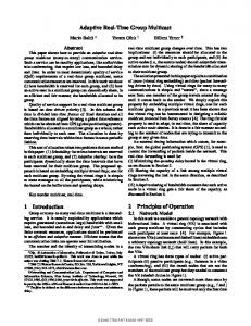
2 System Model Switches are the basic building blocks of multistage networks. In a k � k switch with turnaround connection (Figure 1), a left-hand side port is labeled `i and a right-hand side port is labeled ri (0 � i � k ? 1). It is assumed that each port is bidirectional and incident with two unidirectional channels (in opposite directions) between neighboring switches. This implies that two messages can be transmitted simultaneously in opposite directions between neighboring switches. In addition, 2
multiple messages can be relayed simultaneously within a switch, provided that each incoming message requires a unique outgoing channel. For ease of explanation, it is assumed that processor nodes are on the left side of the network, as shown in Figure 2. 0
0
1
1
internal labels
backward
forward
turnaround
(a) a 2x2 switch with turnaround connection
1
0 1
2 3
3
0
2
internal labels
backward forward (b) a 4x4 switch with turnaround connection
turnaround
Figure 1. Examples of switches with turnaround connection A switch supports three types of connections: forward, backward, and turnaround. For simplicity, the input device on port `i (rj ) is denoted as input port `i (rj ), and the output device on port `i (rj ) is denoted as output port `i (rj ). In forward connection, input port `i is connected to output port rj , where 0 � i; j � k ? 1. In backward connection, input port ri is connected to output port `j , where 0 � i; j � k ? 1. In turnaround connection, input port `i is connected to output port `j , where 0 � i 6= j � k ? 1. No connection is allowed from input port ri to output rj , where 0 � i 6= j � k ? 1. This property avoids the potential deadlock for the shortest-path wormhole routing. Note that multiple arcs in Figure 1 mean the possible connections, not hardware broadcast. In this paper a channel refers to a unidirectional communication channel. A channel connecting an output port at switch Gm to an input port at switch Gm+1 is called forward channel. A channel connecting an output port at switch Gm to an input port at switch Gm?1 is called backward channel. For simplicity, the results in this paper are presented using multistage cube network, a popular type of multistage network. An N -port multistage cube network built with k � k switches can be represented as C0 (N )G0 (N=k)C1 (N ) : : : Cn?1 (N )Gn?1 (N=k)Cn (N ) where Gi refers to the ith stage, Ci refers to the ith connection, and N = kn . There are n stages. Each stage Gi consists of N=k identical k � k switches and thus is denoted as Gi(N=k). Each connection Ci connects N right-hand side ports at stage Gi?1 to N left-hand side ports at stage 3
Gi and thus is denoted as Ci (N ). A connection pattern Ci de nes the topology of the one-to-one correspondence between Gi?1 ports and Gi ports, also known as a permutation. In a multistage cube network, connection pattern Ci is described by the ith butter y permutation ik which can be formalized as follows:
De nition 1 The ith k-ary butter y permutation ik , for 0 � i � n ? 1, is de ned by ik (xn?1 : : : xi+1 xixi?1 : : : x1 x0 ) = xn?1 : : : xi+1 x0 xi?1 : : : x1 xi where 0 � xi � k ? 1.
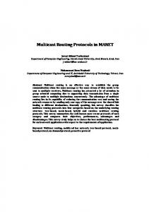
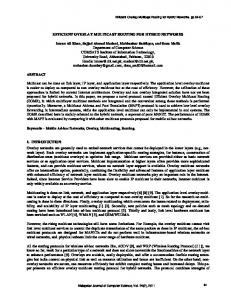
For simplicity, 0k is selected to be connection pattern Cn . Figure 2 shows the system architecture which consists of an 8-port multistage cube network built with 2 � 2 switches. processor memory C0
G0
C1
G1
C2
G2
000 001 010 011 100 101 110 111
Nodes Turnaround Butterfly BMIN
Figure 2. System architecture In Figure 2, processor nodes represented by circles are interconnected through a multistage cube network. All nodes are attached to the same side of the network. Available ports on the other side of the network are used to con gure large networks. Each node has local processor and local memory. Remote memory access can only be achieved by message-passing. Messages are relayed using the wormhole routing switching technique [12]. In this paper, it is assumed that there is 4
exactly one input channel and one output channel connecting a node to the network, resulting in the so-called \one-port communication architecture". This assumption, which is consistent with many existing multistage network systems, implies that the local processor must transmit (receive) message in sequential. Commercial SPCs, using multistage cube networks with turnaround switching and wormhole routing, include the TMC CM-5 [13], Meiko CS-2 [14], and IBM SP-1 [2]. Among them, Meiko CS-2 and IBM SP-1 strictly uses one-port communication architecture. In the CM-5, the rst two level stages use 4 � 2 switches, yielding a dual-port communication architecture. Communication latency latency consists of three component values: start-up latency , network latency , and blocking time [15]. The start-up latency refers to the time required for message framing/unframing, memory/bu�er allocation, validation, and so on, at both source and destination nodes. Start-up latency can be further classi ed into sending latency, the software latency at source node, and receiving latency, the software latency at destination node. The network latency equals the elapsed time after the head of a message has entered the network at the source until the tail of the packet emerges from the network at the destination. The blocking time includes all possible delays encountered during the lifetime of a message. These delays are mainly due to con icts over the use of shared resources, for example, a message encountering a busy channel or a full bu�er. In this paper, multicast latency is used to measure multicast performance. The multicast latency refers to the time interval from when the source processor begins to send the rst copy of the message until the last destination processor has received the message.
3 The Turnaround Routing Taking advantage of turnaround switches and wormhole routing, the turnaround routing algorithm (Figure 3) is used for unicast communication in our network system model. In a multistage cube network built with k � k switches, source address S and destination address D are represented by k-ary numbers sn?1 : : : s1 s0 and dn?1 : : : d1 d0 , respectively. Function FirstDi�erence(S; D) returns t, the position where the rst (leftmost) di�erent digit appears between sn?1 : : : s1 s0 and dn?1 : : : d1 d0 . More formally, it can be de ned as follows:
De nition 2 FirstDi�erence(S,D)= t if and only if st 6= dt and si = di for t < i < n.
5
Algorithm: Turnaround routing in each switch at stage j
Input: Source address S : sn?1 : : : s1s0
Destination address D : dn?1 : : : d1 d0
Procedure:
t =FirstDi�erence(S; D) (j � t is always true) If j = t, then take a turnaround connection to output port `d If j < t and the message comes from an input port `i , then take a forward connection to any available output port rh (0 � h � k ? 1) If j < t and the message comes from an input port ri , then take a backward connection to the ouput port `d Figure 3. The turnaround routing algorithm executed in each switch j
j
To route a message from source to the destination, the message is rst sent forward to stage Gt . It does not matter which switch at stage Gt the message reaches. Then, the message is turned around and sent backward to the destination. As it moves forward to stage Gt , a message always takes forward channels. There may be multiple choices as to which forward channel to take in each stage Gj where 0 � j < t. The decision can be resolved by randomly selecting from among those forward channels which are not blocked by other messages. After the message has attained a switch at stage Gt , it takes the unique path from that switch backward to its destination. The backward routing path only consists of backward channels and can be determined by the \destination tag" routing: the message takes backward channel ejecting from output port `d in a switch at stage Gj . Note that the number of forward channels and the number of backward channels traversed by a turnaround routing path are always same. The turnaround routing is essentially the fat tree routing [16]. The detailed study and performance evaluation of turnaround routing can be found in [17]. Figure 4 gives an example of turnaround routing in an 8-port multistage cube network built with 2 � 2 switches. In Figure 4, the function FirstDi�erence(001,101) returns 2. The message is rst sent from S to any switch at stage G2 , say F . Note that path A ! B ! F is randomly selected. An alternative could be A ! C ! E . Then, the message is turned around in F and sent backward to D. Path F ! G ! H ! D is the unique path from F to D. This path is determined by taking output port `1 on F , output port `0 on G, and output port `1 on H . j
6
000
0
B
A
S
001
1
010
100
0
H
D
E
C
011
G
F
101 1
1
110 111
C0
G0
C1
G1
C2
G2
FirstDifference(S, D)=2
Figure 4. An example of turnaround routing Since a message only turns around once from a forward channel to a backward channel, the dependency graph for the routing paths selected in this way is free from cycles. Therefore, the turnaround routing is deadlock free. By the butter y connection, stage Gt where t =FirstDi�erence(S; D) is the least common ancestor of processors S and D. Therefore, the turnaround routing is the shortest-path routing. On the other hand, when it moves forward, a message can choose an arbitrary forward channel at a switch (there is no redundancy for backward channels). There are multiple choices of the shortest path which the turnaround routing may select between a source and a destination. This property can be formalized as follows:
Theorem 1 In an N -port multistage cube network built with k � k switches (N = kn), there are kt
shortest paths between source S and destination D, each of which can be generated by the turnaround routing algorithm, where t =FirstDi�erence(S,D).
Since the forward channel selection is random, it is possible for two messages transmitted simultaneously to compete for the same backward channel, even though these two messages have the distinct sources and the distinct destinations. As a result, the multistage cube network with turnaround routing is a blocking network. In Figure 5, the message sent from node 011 to node 111 and the message sent from node 001 to node 110 contend for a common channel, backward channel ejecting from port `1 at the bottom switch in stage G1 .
7
000
S1 001 010
S2 011 100 101
D1 110 D2 111 1
blocking
G1
Figure 5. Blocking network
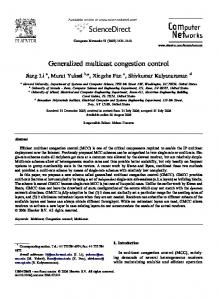
4 The Problem Although hardware implementations of multicast communication would intuitively o�er better performance than software implementations, many such implementations are restricted in their use. For example, the TMC CM-5 can only support hardware broadcast by using a separate control network. The NEC Cenju-3 claims to provide restricted multicast in hardware with the limitation that all destination addresses must be consecutive. In fact, many existing wormhole-routed SPCs support only unicast communication in hardware. In these environments, the multicast tree must be implemented in software by sending multiple unicast messages. However, unlike separate addressing, in a multicast tree, the source node actually sends the message to only a subset of the destinations. Each recipient of the message forwards it to some subset of the destinations that have not yet received it. The process continues until all destinations have received the message. Which types of multicast trees to use depends on the switching strategy and unicast routing algorithm. An e�cient multicast tree involves no local processors other than the source and destination processors, exploits the distance-insensitivity of wormhole routing [15], and is of minimum height, speci cally, height dlog2 (m)e for m ? 1 destination nodes. Another key requirement is that there be no channel contention among the constituent messages of the multicast. That is, the unicast messages involved should not simultaneously require the same channel. Addressing the practical consideration of channel contention among the constituent messages of multicast operations, and the theory behind the resultant algorithms, distinguishes the approach presented in this 8
0011
[1] 0011
0001
[2]
[1]
[2]
0001
0111
[2]
[3]
1100
1010
[3] 0110
0111
[4]
0110
1101
[3] 1010
[3]
1101
1100
0000
0000
0001
0001
0010
0010
0011
0011
0100
0100
0101
0101
0110
0110
0111
0111
1000
1000
1001
1001
1010
1010
1011
1011
1100
1100
1101
1101
1110
1110
1111
1111
(b) Channel Collision occurs at step 2 and step 3
(a) A binary multicast tree
source
[3]
[2]
area of potential contention
destination
Message sent in step 1 Message sent in step 2 Message sent in step 3 Message sent in step 4
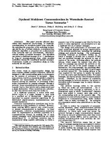
Figure 6. Unicast-based software multicast trees paper from previous investigations. The following (small-scale) example is used to illustrate issues and di�culties involved in implementing e�cient multicast communication in wormhole-routed multistage cube networks with turnaround routing. As shown in Figure 6, consider the 16-port multistage cube network built with 2 � 2 switches. Suppose a multicast message is sent from source 0011 to six destinations f0001; 0110; 0111; 1010; 1100; 1101g. Figure 6(a) shows a binary multicast tree. At step 1, the source sends the message to node 0111. At step 2, nodes 0011 and 0111 inform nodes 0001 and 1100, respectively. Continuing in this fashion, this implementation requires 4 steps to reach all destinations. Taking advantage of the distance insensitivity of wormhole routing, the duration of each step must be approximately equal to the duration of a single unicast transmission of the message. In other words, it should be correct to assume that each step requires unit time as long as there exists no channel contention among 9
0011
2t
0011
7t
0001
[2] 1101
0110
0001
0111
7t 1010
0111
[3]
[1]
4t
3t 4t 6t
6t
[2]
[3]
1100
1010
0110
[3] 1100
1101
0000
0000
0001
0001
0010
0010
0011
0011
0100
0100
0101
0101
0110
0110
0111
0111
1000
1000
1001
1001
1010
1010
1011
1011
1100
1100
1101
1101
1110 1111
1110 1111
(d) Collision−free multicast tree, regardless of message length or receiving latency
(c) Collision may occur if sending latency is large
source
area of potential contention
destination
Message sent in step 1 Message sent in step 2 Message sent in step 3
Sending latency: 2t
The time when a message is injected in the network
Receiving latency: t
The time when a message arrives at the destination host interface
Network latency: t
The time when a message is received by the destination process
Figure 7. Unicast-based software multicast trees (cont'd) the messages transmitted during each step. For this reason, the multicast latency in Figure 6(a) is 4 time steps. In Figure 6(b), the shape of the tree is rearranged in a way that the number of steps to complete the tree can be reduced to 3. However, closer inspection reveals that the message sent from node 0001 to node 0111 and the message sent from node 0011 to node 0110 in step 2 use a common channel. The contention for that channel would force one of the messages to block while the other is using the channel. Consequently, these two unicasts cannot take place during a single time step. The channel collision which occurs between two messages transmitted simultaneously within the same step in a multicast tree is known as stepwise contention [7]. Similarly, there is 10
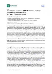
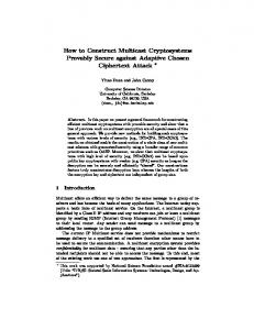
another stepwise contention between the message sent from node 0111 to node 1100 and the message sent from node 0011 to node 1101. As a result, the multicast latency in Figure 6(b) is actually larger than 3 time steps. This situation is recti ed in Figure 7(c), where the messages sent within a particular time step do not contend for common channels. Contention among messages sent in di�erent steps may arise, however, if the message length is small and the sending latency is large. In the IBM SP-1, the sending latency is about 20�sec, the receiving latency is about 9�sec, and the network latency is about 0:16�sec per byte. Using these SP-1 latency parameters, we assume that in our example system (Figure 6 and Figure 7) the sending latency 2t, the receiving latency t, and the length of the multicast message is chosen in a way that its network latency is t. As shown in Figure 7(c), the message transmission from node 0001 to node 0111 and the message transmission from node 0011 to node 0110 take place concurrently during the time period between 6t and 7t, and contention occurs for the shadowed channel. The channel collision which occurs among concurrently transmitted messages due to small message size or large start-up latency is known as depth contention. The multicast tree in Figure 7(d), which is based on the methods to be presented in the following section, is both stepwise contention-free and depth contention-free. Generally speaking, with no channel collision, given (m ? 1) destination nodes, dlog2 me is the greatest lower bound of the number of time steps a multicast algorithm can attain.
5 The U-min Algorithm This section describes U-min, an optimal multicast algorithm (Figure 8) which achieves the greatest lower bound of the number of time steps. The name \U-min" is chosen for the unicast-based multicast for multistage interconnection networks. In Figure 8, source and destination addresses are rst sorted in the lexicographic order, known as a lexicography-ordered chain. A lexicography-ordered chain is denoted as �, at the time when multicast is initiated by calling the U-min algorithm. The source successively divides � in half. If the source is in the lower half, then it sends a copy of the message to the smallest destination (with respect to the lexicographic order) in the upper half. That destination will be responsible for delivering the message to the other destinations in the upper half, using the same U-min algorithm.
11
If the source is in the upper half, then it sends a copy of the message to the largest destination in the lower half. The source continues this procedure until � contains only its own address. Figure 9 shows how to obtain the optimal multicast implementation (Figure 7(d)) by using the U-min algorithm. The source begins with a lexicography-ordered chain � = f0001; 0011; 0110; 0111; 1010; 1100; 1101g. As shown in Figure 9, the source 0011 rst sends to node 0111, the node with the lowest address in the upper half of �. The upper half is deleted from �, and therefore the nodes remaining in � are f0001; 0011; 0110g. Since it locates in the middle of the lower half chain, source 0011 next sends to node 0001, the nearest node on the left-hand side. Finally, 0011 sends to 0110. Each of the receiving nodes is likewise responsible for delivering the message to the nodes in its subtree using the same algorithm. As shown in Figure 9, this multicast implementation requires 3 time steps.
Algorithm: U-min Algorithm Inputs: �: lexicography-ordered chain fd` ; dl+1 ; : : : ; dr g for source
and destination addresses ds: the address of source nodes
Procedure: while ` < r do if s < `+2 r then /* send right */ c = ` + d r?2 ` e; D = fdc ; dc+1 ; : : : ; dr g; r = c ? 1; else if s > `+2 r then /* send left */ c = ` + b r?2 ` c; D = fd` ; : : : ; dc?1 ; dc g; ` = c + 1; else /* send left */ c = s ? 1; D = fd` ; : : : ; dc?1 ; dc g; ` = s;
endif
Send a message to node dc with the address eld D;
endwhile
Figure 8. The U-min algorithm Developing an optimal software multicast algorithm for a speci c system such as a multistage cube network with turnaround routing requires a detailed understanding of potential con icts among messages. The following properties are critical to the development of the U-min algorithm 12
0001
0011
0110
1010
0111
1101
1100
Lexicography−ordered chain
step 1
0001
0011
0110
0111
1010
step 2
0001
0011
0110
0111
1010
step 3
0001
0011
0110
source
0111
destination
1010
1100
1101
1101
1100
1100
1101
transmission at step i
Figure 9. An example of using the U-min algorithm because they indicate how channel contention may be avoided. The formal proof of these theorems can be found in Appendix.
Theorem 2 In a multistage cube network with turnaround routing, u, v, x, and y are processor
node addresses. If u < v < x < y or v < u < y < x, then there is no channel shared by the message transmitted from u to v and the message transmitted from x to y.
Theorem 3 In a multistage cube network with turnaround routing, u, v, x, and y are processor
node addresses. If u < v < x < y, then there is no channel shared by the message transmitted from x to y and the message transmitted from v to u.
In the U-min algorithm, � can be partitioned into two halves. The lower half and the upper half are de ned on either side (with respect to the lexicographic order) of the source address. By the construction of the U-min algorithm, any message sent by a node di in the lower half will be destined for another node dj , dj < di , in the lower half. Similarly, any message sent by a node di in the upper half will be destined for another node dj , di < dj , in the upper half. Thus, Theorem 2 can be used to prove both stepwise contention-free and depth contention-free message transmission within the lower half and the upper half, respectively. Furthermore, Theorem 3 proves that no channel contention can exist in the constituent unicast messages between the two halves. As a result, the proposed algorithm achieves the minimum multicast latency in a turnaround-routed multistage cube network built with any k � k switches.
13
6 Experimental Results Our experimental study was conducted on a 64-node IBM SP-1 at Argonne National Laboratory. In the IBM SP-1, each processor node is an IBM RS6000. Each frame consists of 16 processor nodes interconnected through eight 4 � 4 switches in two stages, as shown in Figure 10. Note that the rightmost stage in our system model (Figure 2) only performs the turnaround routing. This redundant stage can be removed by the proper wiring which connects two frames directly. The interconnection network architecture of a 32-port IBM SP-1 is topologically equivalent to the model shown in Figure 10 with no need of the rightmost stage. The unused links can be used to construct larger networks. Frame 1 000 001 002 003 010 011 012 013 020 021 022 023 030 031 032 033 100 101 102 103 110 111 112 113 120 121 122 123 130 131 132 133
Frame 2
Figure 10. A 32-port multistage network topologically equivalent to a 32-port IBM SP-1 Only wormhole-routed unicast communication is supported in hardware on the SP-1. Broadcast, multicast, and other collective communication primitives have to be implemented in software. A 14
unicast message is transmitted using the turnaround routing when the source processor and the destination processor are allocated to the same frame, such as the message transmitted from node 023 to node 030 and the message transmitted from node 122 to node 131 in Figure 10. If the source processor and the destination processor are allocated to di�erent frames, a unicast message will be sent by taking a shortest path across two frames, such as the message transmitted from node 000 to node 101 in Figure 10. As a result, the unicast routing across two frames can also be characterized by the turnaround routing. As of the time of experiment, the EUI-H, a high-performance external user interface, was provided as the low-overhead implementation of the message-passing library in the IBM SP-1 [18]. In the SP-1 available at Argonne National Laboratory, two di�erent sets of message-passing interface software were implemented upon the EUI-H: Chameleon and MPI-F. Chameleon [19] is a collection of routines that support parallel programming on various distributed-memory parallel platforms. MPI-F [20] is an experimental implementations of the emerging Message Passing Interface (MPI) standard for the IBM SP-1. The MPI-F collective communication library, however, had not yet been optimized and used the same routines available in the public domain MPI [11] as of the time of experiment. Both Chameleon and MPI-F provide collective communication routines including the application-level broadcast. In both environments, any subset of processors can form an application group in which a broadcast operation can be invoked. Such an application-level broadcast operation is essentially a system-level multicast. Figure 11 compares four multicast implementations on a 64-node IBM SP-1: separate addressing, Chameleon application-level broadcast, MPI-F application-level broadcast, and software U-min algorithm. The separate addressing and U-min algorithm were implemented upon the EUI-H through Chameleon. The performance of each implementation was measured with no background tra�c. As shown in Figure 11, the U-min algorithm outperforms the other three approaches in all cases. Based on the authors' experience in programming the SP-1 at Argonne National Laboratory as of the time of reporting, the mapping between the virtual processor identi er and the physical processor identi er was completely random. As a result, the U-min algorithm rst sorted source and destinations in the lexicographic order with regard to their physical processor addresses. This ordering property made the performance of the U-min algorithm superior over Chameleon broadcast and MPI-F broadcast operations. The performance of the U-min algorithm was consistently about 15
Multicast Latency (msec)
5 4 3
Message size: 400 bytes 2 64-node SP-1 2 U-min 4 2 2 Chameleon 2 MPI-F + Separate 2 2 2 Addressing
22
2 2 +2 + + + + + + + + + + + + 1 + + +2 2 244444444444444 4 2 4 0
2
3 7 11 15 19 23 27 31 35 39 43 47 51 55 59 63 Number of Destinations
Figure 11. Comparison of multicast algorithms on a 64-node IBM SP-1 30% better than the Chameleon application-level broadcast. The performance improvement was expected to be greater for a multicast message with a larger size or for a larger system. Using the bit vector representation, the overhead of sorting source and destination addresses into the lexicographic order is insigni cant and thus can be neglected. In a 64-node system, the elapsed time for executing the sorting routine is less than 9 �sec which is only 4% of the latency of a single unicast transmission for a 400-byte message.
7 Conclusions This paper has proposed an optimal multicast algorithm for wormhole routed multistage networks that o�er the turnaround unicast routing and provide a single bidirectional port at each node connecting the local processor to the interconnection network. The proposed multicast algorithm attains both stepwise contention freedom and depth contention freedom. This property guarantees that the minimum multicast latency can always be achieved regardless of the message size or startup latency. The algorithm has been implemented on a 64-node IBM SP-1 and has demonstrated its superiority over other application-level broadcast services provided by currently existing collective communication libraries. The proposed algorithm can be readily applied to the Meiko CS-2 which uses a similar interconnection network as the IBM SP-1. 16
Though the one-port communication architecture model used in this paper is consistent with most commercial SPCs, research of e�cient data communication on multiple-port communication architectures is becoming popular. One area of the authors' current research concerns construction of an e�cient algorithm speci cally for wormhole-routed multistage networks which support multiple-port communication, such as the TMC CM-5. In addition, the concern of channel collision avoidance can be applied to other collective communication primitive designs in order to explore the maximum system performance.
Acknowledgements The authors would like to thank Dr. Howard C.T. Ho of IBM Almaden Research Center for his many useful suggestions regarding this work and the Argonne National Laboratory for the use of their IBM SP-1 machine, respectively.
17
References [1] BBN Advanced Computers Inc., Cambridge, Massachusetts, Inside the TC2000 Computer, 1990. [2] C. B. Stunkel et al., \Architecture and implementation of Vulcan," in Proc. of the 8th International Parallel Processing Symposium, pp. 268{274, Apr. 1994. [3] N. Koike, \NEC Cenju-3: A microprocessor-based parallel computer," in Proc. of the 8th International Parallel Processing Symposium, pp. 396{401, Apr. 1994. [4] Message Passing Interface Forum, \MPI: A Message-Passing Interface Standard," tech. rep., University of Tennessee, Mar. 1994. [5] H. Xu, P. K. McKinley, and L. M. Ni, \E�cient implementation of barrier synchronization in wormhole-routed hypercube multicomputers," Journal of Parallel and Distributed Computing, vol. 16, pp. 172 { 184, October 1992. [6] H. Xu, E. T. Kalns, P. K. McKinley, and L. M. Ni, \ComPaSS: A communication package for scalable software design." accepted to appear. [7] P. K. McKinley, H. Xu, A. H. Esfahanian, and L. M. Ni, \Unicast-based multicast communication in wormhole-routed direct networks," in Proceedings of the 1992 International Conference on Parallel Processing, vol. II, pp. 10{19, Aug. 1992. [8] A. Bar-Noy, J. Bruck, C.-T. Ho, S. Kipnis, and B. Schieber, \Computing global combine operations in the multi-port postal model," in Proceedings of the fth IEEE symposium on parallel and distributed processing, pp. 336{343, Dec. 1993. [9] D. F. Robinson, D. Judd, P. K. McKinley, and B. H. C. Cheng, \E�cient collective data distribution in all-port wormhole-routed hypercubes," in Proceedings of Supercomputing'93, pp. 792{801, Nov. 1993. [10] C.-T. Ho and M.-Y. Kao, \Optimal broadcast on hypercubes with wormhole and E-cube routings," in Proceedings of the 1993 International Conference on Parallel and Distributed Systems, pp. 694{697, 1992. [11] W. D. Gropp, E. Lusk, and A. Skjellum, Using MPI: Portable Parallel Programming with the Message-Passing Interface. MIT Press, 1994. [12] W. J. Dally and C. L. Seitz, \The torus routing chip," Journal of Distributed Computing, vol. 1, no. 3, pp. 187{196, 1986. [13] C. E. Leiserson et al., \The network architecture of the Connection Machine CM-5," in Proceedings of the ACM Symposium on Parallel Algorithms and Architectures, (San Diego, CA.), pp. 272{285, Association for Computing Machinery, 1992. [14] Meiko Limited, Waltham, MA., Computing Surface: CS-2 Communications Networks, 1993. [15] L. M. Ni and P. K. McKinley, \A survey of wormhole routing techniques in direct networks," IEEE Computer, vol. 26, pp. 62 { 76, Feb. 1993. [16] C. E. Leiserson, \Fat-trees: Universal networks for hardware-e�cient supercomputing," IEEE Transactions on Computers, vol. C-34, pp. 892{901, Oct. 1985. 18
[17] L. M. Ni, Y. Gui, and S. Q. He, \Performance evaluation of multistage wormhole networks with turnaround routing," Tech. Rep. MSU-CPS-ACS-96, Michigan State University, July 1994. [18] W. Gropp, E. Lusk, and S. Pieper, \Users Guide for the ANL IBM SP-1 DRAFT," Tech. Rep. ANL/MCS-TM-00, Argonne National Laboratory, Feb. 1994. [19] W. Gropp and B. Smith, \Users manual for the Chameleon parallel programming tools," Tech. Rep. ANL-93/23, Argonne National Laboratory, June 1993. [20] H. Franke, \MPI-F: An MPI implementation for IBM SP-1," Feb. 1994. Available on anonymous ftp from info.mcs.anl.gov. [21] A. V. Aho, J. E. Hopcraft, and J. D. Ullman, Data Structures and Algorithms. Addison-Wesley, 1983.
19
A Channel Collision-Free Results 0000 0001 0010 0011
A
A
A
A
A
A
A
A
A
A
A
A
B
B
B
B
C
C
C
C
0100 0101 0110 0111 1000 1001 1010 1011 1100 1101
1110 1111
(a) a 16−port multistage cube network built with 2x2 swtiches
Ba ck
ard
wa
rw
rd
Fo
A
B
C
(b) a 16−port fat tree
Figure 12. Fat tree and multistage cube network As shown in Figure 12, a multistage cube network with turnaround routing is topologically equivalent to a fat tree [16]. An interior tree vertex with the height h 2 represents a set of switches at stage (n ? h) where n is the total number of stages in the multistage cube network. For example, vertex \A" in Figure 12(b) corresponds to the top four switches at stage 3 in Figure 12(a). Leaves in the tree represent processors. Each tree edge is composed of the channels which connect one of the switches represented by child node and one of the switches represented by parent node. The 2
The height of the tree root is 0. 20
aggregated bandwidth of a tree edge is proportional to the number of the forward (or backward) channels bundled up by the tree edge. As shown in Figure 12(b), given any interior node, the aggregated bandwidth of the parent connection is equal to the sum of the aggregated bandwidth of each child connection. A subtree rooted at an interior vertex represents a subnetwork partition in a multistage cube network. For example, subnetworks \A", \B", and \C" in Figure 12(a) corresponds to subtrees rooted at interior vertices \A", \B", and \C" in Figure 12(b), respectively. The turnaround unicast routing can be perfectly described by the tree routing. When a message is routed from one processor to another, it is sent up to the least common ancestor of the two vertices representing the two processor nodes, and then sent down to the destination. For example, in Figure 13, the message from processor node u to processor node v takes the route ue1 Ae2 Be3 Ce4 De5 Ee6 Fe7 Ge8 v where e1, e2 , e3 , and e4 are forward channels, D is the least common ancestor of u and v, and e5 , e6 , e7 , and e8 are backward channels. Given a source u and a destination v, P (u; v) = uw1 w2 : : : wn v is denoted as the path connecting u and v in the fat tree where w1 , w2 , : : :, and wn are tree vertices. Though the tree path P (u; v) = uw1 w2 : : : wn v is unique, there are multiple choices of channel selection upon each tree edge (wi ; wi+1 ) where 1 � i � n ? 1. When it is sent up, a message can take any available forward channel connecting to the parent vertex. However, each backward channel constituting the path from the least common ancestor to the destination is unique. D
Ba ck
d ar e
e
4
rd
wa
rw
Fo
5
C
E e
e 3
B
6
F e
u
e
2
7
A
G
e
e
1
8
v
x
y
Figure 13. Turnaround routing modeled by the fat tree The tree vertices including the root, interior vertices, and leaves are labeled using the breadth rst searching (BFS) [21] algorithm, which has the following important properties. 21
Lemma 1 If vertices in a tree are labeled using the BFS, the labels of leaves are in the increasing order starting with the leftmost leaf position.
The proof of the lemma is trivial and can be found in [21]. This lemma implies that for processor nodes, the mapping between their IDs and their labels in the tree is monotonous. For this reason, given processor nodes x and y, the symbol \x < y" indicates that the x's processor ID is less than the y's and the x's label in the tree is less than the y's as well.
Lemma 2 Suppose that vertices in a tree are labeled using the BFS. Given three leaves x, y, and z where x < y < z, a common ancestor of vertices x and z must be an ancestor of vertex y.
The proof of the lemma is trivial and can be found in [21]. In Figure 13, v < x < y. E is an ancestor of v and y. Thus, E is also an ancestor of x. Theorem 2 and Theorem 3 are proved as follows:
Theorem 2 In a multistage cube network with turnaround routing, u, v, x, and y are processor
node addresses. If u < v < x < y or v < u < y < x, then there is no channel shared by the message transmitted from u to v and the message transmitted from x to y.
Proof:
Without loss of generality, we assume that u < v < x < y. Suppose that vertex w1 is the least common ancestor of vertices u and v, and vertex w2 is the least common ancestor of vertices x and y in the fat tree which models the given multistage cube network. Thus, P (u; v) is concatenated by P (u; w1 ) and P (w1 ; v), and P (x; y) is concatenated by P (x; w2 ) and P (w2 ; y). 1 Consider P (u; w1 ) and P (w2 ; y). Since P (u; w1 ) only consists of forward channels and P (w2 ; y) only consists of backward channels, there is no channel shared by P (u; w1 ) and P (w2 ; y). 2 Consider P (w1 ; v) and P (x; w2 ). Since P (w1 ; v) only consists of backward channels and P (x; w2 ) only consists of forward channels, there is no channel shared by P (w1 ; v) and P (x; w2 ). 3 Consider P (u; w1 ) and P (x; w2 ). Both P (u; w1 ) and P (x; w2 ) consist of forward channels. In the turnaround routing, when a message moves forward, it can take any forward channel which is not blocked by other messages. On the other hand, the number of forward channels ejected from an interior vertex is equal to the number of the leaves in the subtree rooted 22
at the vertex. Thus, there is always a forward channel available for each processor on each interior node. As a result, the property of arbitrary forward channel selection makes P (u; w1 ) and P (x; w2 ) free of channel sharing. 4 Consider P (w1 ; v) and P (w2 ; y). Both P (w1 ; v) and P (w2 ; y) consist of backward channels. By contradiction we prove that there is no channel shared by P (w1 ; v) and P (w2 ; y). Suppose there is a backward channel (z1 ; z2 ) (from z1 to z2 ) shared by P (w1 ; v) and P (w2 ; y). Thus, z2 is a common ancestor of v and y. By Lemma 2, since v < x < y, z2 is an ancestor of x. Thus, z2 is a common ancestor of x and y. On the other hand, since vertex z2 is included in the down-tree path P (w2 ; y), w2 is an ancestor of z2 . This contradicts with the assumption that w2 is the least common ancestor of x and y. Therefore, no channel can be shared between P (w1 ; v) and P (w2 ; y). The second half of the theorem, that no channel is shared by P (u; v) and P (x; y) when v < u < y < x, is proved in a similar manner. 2
Theorem 3 In a multistage cube network with turnaround routing, u, v, x, and y are processor
node addresses. If u < v < x < y, then there is no channel shared by the message transmitted from x to y and the message transmitted from v to u.
Proof: Theorem 3 is proved in a similar manner as Theorem 2 is proved.
23
2