This is due to the skin effect, which can be described for the case of penetration of a plane electromagnetic wave from vacuum into a conductive material with ...
Optimisation of Low Frequency Eddy Current Sensors Using Improved Inductive Coils and Highly Sensitive AMR and GMR Sensor Modules S. Cherepov1, O. Hesse2, G. Mook3, S. Pankratyev1, V. Uchanin4 1
2
Institute of Magnetism of the National Academy of Science of Ukraine, Kiev, Ukraine Institut für Maschinen, Antriebe und elektronische Gerätetechnik gGmbH, Nordhausen, Germany 3 Otto-von-Guericke-Universität Magdeburg, Magdeburg, Germany 4 Leotest Medium Center, Lviv, Ukraine
A b s t r a c t Optimisation of low frequency eddy current probes was performed using traditional inductive coils and commercially available AMR and GMR sensors and sensor modules. Results of three groups are presented demonstrating that such kind of eddy current probes show high penetration and sensitivity at low testing frequencies. The lack of objective criteria for comparison had to be stated. A Round Robin test is proposed between the presented groups with more objective criteria to be established before and during the test. I. Introduction Eddy current testing techniques are very sensitive for detection of surface defects in conductive material. Conventional eddy current sensors (ECS) for material defectoscopy usually consist of primary coil inductors for eddy current excitation and secondary inductive coils for signal pick up. Such sensors can be used at testing frequencies in a range of several kHz up to several MHz. An overview of conventional eddy current sensing techniques for material defectoscopy can be found in [1]. For detection of subsurface or deep defects the testing frequencies have to be as low as possible in order to increase the eddy current penetration depth. This is due to the skin effect, which can be described for the case of penetration of a plane electromagnetic wave from vacuum into a conductive material with infinite and plane boundary by equation [2] ⎛ x⎞ i(x ) = i0 ⋅ exp⎜ − ⎟ , (1) ⎝ δ⎠ 1 , (2) δ= π ⋅σ ⋅ µ ⋅ f where i 0 – the current density at the surface, i(x) – the current density at the depth x , δ – the skin depth, σ – the electrical conductivity, µ – the magnetic permeability and f – the excitation frequency. Conventional ECS show decreasing sensitivity with lower testing frequencies. First of all the excitation efficiency decreases with decreasing frequency. The sensitivity of inductive coils for detection of alternating magnetic fields also decreases with decreasing frequency. Furthermore we have to understand that the intrinsic noise of inductive coils dramatically increases with lower frequency, thus leading to a decreasing noise limited resolution for magnetic field measurements. There are some specific cases of eddy current excitation where the magnetic field and current density distribution can be described analytically, for example − plane electromagnetic wave propagation from vacuum to conductive material with infinite and plane boundary and magnetic field vector parallel to the plane of the boundary [2]; − cylindrical solenoid of infinite length with conductive material inside [3]; − cylindrical short coil over conductive material with infinite plane boundary [4]. For most of the cases of practical interest numeric computation methods (e.g. FEM) should be used. In some cases they already allow to predict real sensor behaviour and means for sensor optimisation. Nevertheless in many cases, especially in the case of deep two- or three-dimensional defects and their detection by low frequency ECS, computing methods are very complex and time consumptive, and an experimental approach seems to be more practicable. II. Means for optimisation of low frequency eddy current sensors First of all let us consider methods for increasing the sensitivity of conventional inductive ECS. Our approach is more an experimental rather than a theoretical one. Inductive pick up coils for eddy current probes have a lot of benefits in comparison with magnetic field sensors (MFS) described below. They can be driven into saturation only in the case of strong excitation. There is no permanent offset voltage, they show a good linear behaviour, their characteristics can not be disturbed or destroyed by application of strong magnetic fields, they show low temperature dependence and they offer high flexibility for integration into special sensor set-ups.
Nevertheless for testing frequencies below 1 kHz permanent MFS have to be taken into consideration as sensing elements in eddy current probes. At low frequencies most of the MFS show much higher sensitivity and better noise limited field resolution than pick up coils. There are some specifics that have to be taken into consideration, when using permanent MFS. Normally some additional electronics are required for reading out these sensors. In case of very sensitive SQUID-sensors these electronics are quite complicated and expensive. The linear field range of permanent MFS is limited. As a rule of thumb we can say that the higher sensitivity the lower the linear range. Their characteristics can be disturbed or even destroyed by application of strong magnetic fields. At least some resetting is required in order to recover the sensor characteristics after application of strong magnetic fields. So we can see that integration of MFS requires additional effort and we will describe specific aspects of using MFS in eddy current sensors below. A. Increased excitation level The most obvious way of increasing the sensor sensitivity is to increase the excitation level. In the case of low frequency eddy current testing low cost hi-fi power amplifiers can achieve this. Although such amplifiers are optimised for 4 or 8 Ω impedance loads, they can easily drive several amperes of excitation current into excitation coils with different impedance. B. More sensitive pick-up coils Several methods for increasing pick up coil sensitivity can be considered. So we can increase the effective diameter, increase the number of turns and use differential or multidifferential arrangements of the pick up coils. Increasing the effective diameter of the pick up coils will result in a drop of lateral resolution. The benefit of such method for increasing the sensitivity is limited, even if lateral resolution is of second order importance. Although the absolute sensitivity of larger pick up coils increases, we cannot use this method without limitation because of limited dynamic range of the amplifier system. For absolute ECS let us define some defect contrast level K as ∆M , (3) K= MH where ∆M – the signal change on the defect and M H – the absolute signal level in areas far from defect inhomogeneities. On punctual and one-dimensional defects this contrast level will decrease with increasing effective diameter of the pick up coil. So after some specific signal level M H leading to saturation of the amplifier system we have to reduce the amplification factor resulting in a drop of the absolute signal change on the defect measurable on the amplifier output. This also means that such coils have to be used in differential or multidifferential arrangements. Another characteristic contrast level of absolute ECS could be defined as ∆M , (4) K'= B∆M 2 where B∆M
2
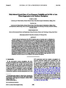
– the defect peak width. K ' was computed assuming that the defect leads to a Gaussian shaped
signature D(x, y ) , which in such form could be detected by a punctual sensing element. A real pick up coil has an aperture function A(x, y ) . Let us assume the aperture function of an absolute pick up coil to be a two-dimensional Gaussian function. The defect signature of a linear defect D(x, y ) is presented on Fig. 1 a-b, the Gaussian shaped aperture function A(x, y ) can be seen in grayscale presentation on Fig. 1 c, the resulting signature M (x, y ) , measurable by such sensor is presented on Fig. 1 d. M (x, y ) can be computed as +∞ M ( x, y ) = ∫ D( x − α , y − β ) ⋅ A(α , β ) ⋅ dα ⋅ dβ (5) −∞
a
b
c
d
Figure 1. Typical defect signature (a, b), aperture function of absolute pick up coil (c) and defect signature measurable by a pick up coil with defined aperture (d).
Figure 2. Contrast level K´ versus pick up coil size (arbitrary units). It can be seen that contrast level K ' , defined by equations (4-5), has a maximum at a specific sensor size, after which it clearly drops down with increasing sensor size (Fig. 2). That means that defect contrast cannot be improved by increasing the sensor size over a specific level. Similar computations for modelling of differential type pick up coils show comparable results. Another means of improvement of the pick up coil’s sensitivity is the increase of number of winding turns and density of winding. We managed to produce coils with several thousands of turns on 0,3 ÷ 1,5 mm diameter ferrite cores with length of 3 ÷ 5 mm. It is obvious that such highly sensitive coils can be used only in differential arrangements. Under common excitation conditions the output signal level may reach up to several volts. C. Usage of differential and multidifferential sensor set-ups There are several benefits in using differential or multidifferential ECS set-ups. The output voltage at pick up coil in case of well compensated differential sensors is quite low allowing to use the full dynamic range of the eddy current amplifier. Lift-off effects can be reduced efficiently. External noise will be cancelled out by differential pick up coils. Probably there will be a reduction of intrinsic noise related to the sensor sensitivity because the differential coils have to be considered as non-correlated noise sources with noise levels added geometrically. Good results in using such sensors were reported in [5, 6 and 7]. D. Usage of permanent magnetic field sensors Eddy current testing at low frequencies requires magnetic field sensitive elements with very good noise limited field resolution. A comparison of different types of MFS was performed in [8, 9]. We measured some noise spectra of commercially available MFS. The results can be seen in Fig. 3.
Figure 3. Noise spectra of commercially available magnetic field sensors. Taking into consideration the noise characteristics of MFS the following ranking (with decreasing field resolution) can be established: − SQUID (Superconductive Quantum Interference Device) − Fluxgates − AMR (Anisotropic MagnetoResistance) sensors − GMR (Giant MagnetoResistance) sensors − Hall sensors Although noise limited field resolution is an important factor for the possible application of permanent MFS in eddy current testing there are other criteria of great importance. They are: geometrical size of the sensor, lateral resolution, orientation sensitivity and cross axis sensitivity, magnetic field and temperature stability of sensor characteristics, linear
field range, complexity of read out electronics, possibility of integration of the sensing elements into a sufficiently small housing, availability and price. We will not give any further information on physical principals of the sensors mentioned above. Detailed description of sensor function can be found in [3, 10 – 13]. Of course, we have to keep in mind that sensor performance is mainly defined by noise limited resolution. But effective de-noising and filtering algorithms of eddy current amplifiers allow significantly reducing noise in very high sensitive GMR sensors. Very good results on penetration depth and sensitivity of ECS with SQUID gradiometers were reported [14]. Testing systems using SQUID sensors are of very high complexity. They are cost expensive and difficult to be used in industrial environment. So the usage of SQUID sensors in low frequency eddy current testing will be limited to some very specific cases. Fluxgates are of much less complexity. Results of using fluxgates or fluxgate type sensors for low frequency eddy current testing are presented in [15, 16]. There is one major disadvantage of using fluxgates in eddy current testing. Normally fluxgates with sufficient sensitivity are quite large, so lateral resolution is expected to be low. Probably better lateral resolution could be achieved by using small excitation coils, but then a sensor set-up is necessary with no direct coupling between excitation and sensor, making the ECS set-up quite difficult. Small excitation coils will also result in less efficient eddy current excitation. Successful usage of commercially available AMR sensors for low frequency eddy current testing was demonstrated in [17]. Simple adaptation electronics were used. The sensor module can be read out directly by a standard eddy current amplifier of the Elotest B1 eddy current instrument (Rohmann) with power supply for the adaptation electronics taken from the power output of the B1 for rotation sensors. Sensor and read out electronics are integrated into one quite compact package. There are two main problems in using AMR sensors. They show cross axis sensitivity not negligible in case of strong eddy current excitation. If AMR sensors are influenced by strong external magnetic fields, this may disturb the sensor characteristics or even result in complete failure of the sensor. In order to stabilise the sensor characteristics of AMR sensors one has to pre-magnetise the AMR stripes, decreasing a little of the AMR sensitivity. A second means for sensor stabilisation is the usage of zero detector read out electronics with negative feedback magnetising coils integrated onto the sensor. The usage of commercially available AMR gradiometer modules [18] with integrated zero detector read out electronics will be demonstrated below. GMR sensors are more robust in usage. There is a very small cross axis sensitivity. After exposing the sensors to strong magnetic fields the sensor characteristics will recover without any additional means. Very sensitive GMR sensor modules are available, but the noise limited resolution of these sensors is smaller than that of AMR sensors. Nevertheless very good performance of such sensors in low frequency eddy current application was demonstrated in [19, 20]. Hall sensors are less sensitive and show bad noise limited field resolution. So probably they cannot be used for low frequency eddy current testing although they have the benefit of very high robustness, stability in strong magnetic fields and very high linear range. III. Experimental investigation of different sensor types and layouts Below we will describe some results of low frequency ECS investigations performed by: − Leotest Medium Center Lviv (Ukraine); − Institute of Materials Engineering and Material Testing at the Otto-von-Guericke University Magdeburg (Germany); − Material testing department of IMG Institut für Maschinen, Antriebe und elektronische Gerätetechnik Nordhausen (Germany). The approach of Leotest Medium Center Lviv was to precisely compensate multidifferential inductive sensors. This allows using the full dynamic range of the eddy current amplifier. A typical layout of such sensor is demonstrated in Fig. 4. Fig. 5 shows the typical signal distribution of eddy current tests performed by scanning this sensor over a holelike defect.
Figure 4. Multidifferential sensor with increased lateral resolution [5].
Figure 5. Signal distribution of eddy current scans with multidifferential sensor over a hole like defect [5].
The performance of such multidifferential sensors was demonstrated by scanning various test blocks with artificial defects. An example of an eddy current image derived from one of the test blocks is given in Fig. 6.
EC probe scanning
Figure 6. Aluminium test block (conductivity 21 MS/m) with ∅4 mm holes of various depth and eddy current distribution image derived by a multidifferential probe according to Fig. 4. Another low frequency ECS was presented by the group of the Institute of Materials Engineering and Material Testing at the Otto-von-Guericke University in Magdeburg [17]. The probe uses a commercially available AMR sensor KMZ10A by Philips Semiconductors [10]. The probe consists of a normal inductive excitation coil and the KMZ10A with chip plane (sensitive direction) perpendicular to the coil axis. There is a differential amplifier-impedance matching board integrated into the sensor housing. As mentioned above power supply is performed by the power output of a Rohmann B1 eddy current amplifier normally used for DC motor rotation eddy current probes. The eddy current probe works at quite low frequencies below 500 Hz. The performance of this probe was also demonstrated by scanning an aluminium test block (Fig. 7).
Figure 7. Test block, sensor outline and test results for an eddy current probe with KMZ10A magnetic field sensor as sensing element [17]. Dealing with eddy current imaging techniques for surface and subsurface defect detection [21] in the material-testing department of IMG we felt there is further potential for improving the low frequency performance of traditional ECS using primary and secondary inductive coils. Using a special grade of 20 µm enamelled copper wire we managed to produce inductive coils on ferrite cores with an outer diameter of about 1,2 mm, of about 6 mm length and number of turns from 2000 up to 5000. Normally to work with such coils we have to use them in differential or multidifferential arrangements. Some sensor configurations produced at the IMG laboratory are shown in Tab. 1. Table 1. Sensor configurations for IMG eddy current probes Nr. 1
2
3
Schematic of the probe
Further explanation Excitation: U-shaped ferrite yoke with excitation coil. Sensing: Two pick up coils with number of turns of about 3000 on ferrite rods with 1,2 mm diameter, 5 mm length and magnetic permeability of about 600, the coils are in series with differential orientation. Excitation: Two coils with axis parallel to the test surface and differential orientation. Sensing: Two pick up coils, 3000 turns on ferrite rods with ∅1,2 mm, 5 mm length and magnetic permeability of about 600. The coils are in series with differential orientation, using pick up coils with 5000 turns we could further increase the sensitivity but with the disadvantage of larger edge effects. Arrows show the magnetic field direction. Excitation: Inductive coil on top of the module. Arrow shows sensitive direction. Sensor: CMS2000 current sensing module [18].
4
Excitation: Yoke with excitation coil. Arrow shows sensitive direction. Sensor: CMS2000 current sensing module [18].
5
Excitation: Inductive coil around the GMR sensor. Arrow shows sensitive direction. Sensor: GMR sensor NVE AAH002-02 [12].
6
Excitation: Two coils with axis parallel to the test surface and differential orientation. Arrow shows sensitive direction. Sensor: GMR sensor NVE AAH002-02 [12].
For demonstration of the sensor performance we used our own aluminium test specimen, shown in Fig. 8. As test defects we have to detect thin (300 µm width) slots of various depth and a length of 30 mm there. Normally the test plate was scanned with the top upside down.
Figure 8. The test specimen: aluminium plate 220x120x5 mm with 8 test slots, slots 1 ÷ 6 on top of the plate, slots 7 and 8 on bottom of the plate. Depth of the slots: 1 – 3 mm; 2 – 2 mm; 3 – 1 mm; 4 – 0,8 mm, 5 – 0,6 mm; 6 – 0,4 mm; 7 – 0,8 mm; 8 – 0,6 mm. Conductivity of the alloy is 19 MS/m.
Figure 9. Dependence of eddy current image of a test slot after scanning the slot with various orientations. As basic configuration for IMG multidifferential inductive eddy current probe configuration we took configuration 1 (Tab. 1). The sensitivity of this probe depends a lot on the orientation of the sensor relative to the test slot (Fig. 9). We had to learn that in case of orientation for maximal current density perpendicular to the slot the signals picked up by the differential pick up coils are cancelled. This is due to the symmetry of the sensor relative to the test slots. Turning the sensor we could find some optimum direction, where the defect signal shows maximum contrast. For that reason we modified the excitation coil arrangement to configuration 2 (Tab. 1). Eddy current distribution images like that in Fig. 10 could be obtained. The original 2D-array of signal values was transformed into false-colour images using logarithmic scale. Here in case of maximum eddy current density perpendicular to the slot the defect signal will not be cancelled because of the anti-symmetric current density distribution relative to the test slot.
Figure 10. Eddy current distribution image on the aluminium test plate of Fig. 8 (starting from bottom left test slots Nr. 1 – 3, 7 – 8 and 4 – 6 are visible with the plate turned upside down). Concerning the usage of highly sensitive MFS in the past we dealt with several kinds of sensing elements beginning with Hall elements and ending with SQUID gradiometers. SQUID sensors require a complex system configuration and their usage will be limited to some very special cases. The lateral resolution of fluxgate sensors based eddy current probes is quite poor. GMR and AMR sensors show good field resolution, they are small in size, thus allowing high lateral resolution. Last but not least they are commercially available at low price. This complex of features makes GMR and AMR sensors a very interesting choice for low frequency eddy current probes. An AMR sensor module is available. It is normally used for current measurement [18], and utilises means of sensor stabilisation. The sensors on these modules are configured in gradiometer arrangement for sensing dH x dx gradients. The sensing elements are stabilised by calibrated permanent magnets placed with high precision onto the sensor board. Coils are integrated onto the Permalloy stripes of the gradiometer and zero detector electronics drive the current in these coils in order to keep the field gradient at zero level. We tested several excitation coil arrangements (Tab. 1, configurations 3 and 4) in order to get optimal orientation of excitation fields, creating minimal field gradient in the sensing area in case of homogeneous structure beneath the sensor but maximised field gradients in presence of defects. Our first experiments on the aluminium test plate showed results comparable with highly sensitive inductive eddy current sensors (Fig. 11 and 12).
Figure 11. Eddy current distribution over test plate Figure 12. Eddy current distribution over test plate according according to Fig. 8 with slots 1 –3 as subsurface defects to Fig. 8 with slots 1 – 3 as subsurface defects (bottom left). (bottom left). Sensor configuration 3 (Tab. 1). Sensor configuration 4 (Tab. 1). With slightly modified sensor geometry and further optimisation of the excitation coil arrangement we are optimistic to achieve much better results at frequencies of 300 ÷ 500 Hz and even below. For this purpose we plan to use commercially available AMR sensors with on chip integrated compensation coils allowing easy zero detection feed back. Two configurations of eddy current probes using commercially available GMR sensors are presented in Tab. 1 (conf. 5, 6). Results obtained by scanning with such eddy current probes with different configurations can be found on Fig. 13.
a
b
Figure 13. Eddy current distribution image using sensor configuration 5 (a) and configuration 6 (b). An objective comparison of these results can be performed only by experiments. This is due to the fact, that the sensitivity of the eddy current system is influenced by a lot of parameters not only of the sensing element but also of the amplifier and the filtering and demodulation algorithms, the scanning system used for eddy current imaging, the scanning speed and the methods of image processing applied for eddy current image enhancement. So we plan to organise a Round Robin Test in order to compare the test results and to stimulate further sensor optimisation. IV. Conclusion It was demonstrated that optimised inductive eddy current probes can be used at low frequencies for hidden defect detection. Best results were obtained by differential and multidifferential probes with very accurate compensation of the differential excitation and pick up coils and increase of pick up coil sensitivity by increasing the number of turns. The application of different types of MFS for low frequency eddy current testing was discussed. Although SQUID and fluxgate sensors are the best choice for low frequency magnetic field measurement, in the case of low frequency eddy current testing less sensitive AMR sensors, sensor modules and even GMR sensors can be used to configure very sensitive low frequency eddy current probes. AMR sensors show much better field resolution but are difficult to handle in eddy current probes because the excitation fields will disturb their characteristics. On the example of an AMR gradiometer based sensor module we could demonstrate the positive influence of stabilising means like premagnetisation and zero detector read out electronics. Investigations for further optimisation of AMR sensor based eddy current probes are still in progress. GMR sensors with quite low noise limited field resolution could be used successfully in very sensitive low frequency eddy current probes. The comparison of results of eddy current testing is quite complicated because of the very high complexity of eddy current testing systems. There is no objective algorithm for comparing results of eddy current testing systems. The visibility of test defects in reference specimens is a quite subjective criterion. Establishing a Round Robin Test between the groups presented in this paper will allow to develop a more objective criterion for sensitivity estimation. References [1] J.R. Davis et. al., ASM Metals Handbook, v.17, Nondestructive Evaluation and Quality Control, ASM International, 1989, ISBN 0-87170-007-7 (v.1). [2] A. Abrikosov, Osnovy teorii metallov, Nauka, Moskva, 1987, pp. 105-106. [3] H. Heptner; H. Stroppe; H. Blumenauer: Magnetische und magnetinduktive Materialprüfung, VEB Deutscher Verlag für Grundstoffindustrie, Leipzig 1965, VLN 152-915/33/65. [4] Dodd C.V.; Deeds W.S.: Analytical Solution to Eddy Current Probe-Coil Problems. Journal of Applied Physics 39 (1968) 6, S. 2829-2838. [5] Uchanin V.; Mook G.; Stepinski T.: The Investigation of Deep Penetrating High Resolution EC Probes for Subsurface Flaw Detection and Sizing, ECNDT 17.- 21.6.2002 Barcelona, AEND. [6] Mook G., Uchanin V.M.: Visualisacija resultatov nerasrushjustschego kontrolja vichretokovym metodom, in: Uchanin V.M. (red.) Fizichni metody ta zasoby kontrol´lju seredovisc, materialiv ta vyrobiv (V meznarodnaja naukovo-techniceskaja konferencija, Leotest ´2000), Lviv, 20-25 Febr. 2000, proceedings pp. 9-16. [7] Uchanin V.M.; Mook G.: Vichrestrumovy kontrol´ korosijnich poschodshen´ dvoscharovich aviacijhich konstrukcij. In: Fizichni metody ta zasoby kontrol´lju seredovisc, materialiv ta vyrobiv, 9: Elektromagnitni ta akusticni metody nerujnivnogo kontrol´ju materialiv ta vyrobiv: 36. nauk. Prac.-Lviv: Fiziko-mechanicnij institut im. G.V. Karpenka NAN Ukraini, 2004, pp. 113-122. [8] KFA Jülich. [9] Schmidl F. et al.: Workshop “Preparation Properties and Applications of Thin Ferromagnetic Films”, Wien, June15-16, 2000.
[10] Philips Semiconductor Handbook SC17. [11] Honeywell Datasheet: Linear Magnetic Field Sensors HMC 1001/1002 and HMC 1021/1022. [12] NVE Corporation, GMR Sensors Data Book, April 2003. [13] Catalogue: Hall sensors; F.W. Bell. [14] R. Hohmann, SQUID-System mit Joule-Thompson-Kühlung zur Wirbelstromprüfung von Flugzeugfelgen, Dissertationsschrift, 1999, Justus-Liebig-Universität Gießen. [15] Gabor Vertesy, Antal Gasparics: Fluxset Sensor Analysis, Journal of Electrical Engineering, Vol. 53, 2002, ISSN 1335-3632. [16] v. Kreutzbruck, M.; Allweins K.; Heiden C.: Wirbelstromprüfsystem mit integriertem Fluxgate-Magnetometer. DACH-Jahrestagung DGZfP, ÖGfZP, SGZP, Innsbruck, 29.-31.5.2000, BB 73.2, pp. 871-881. [17] Mook, G.; Bauke, H.; Uchanin, V.: Besonderheiten der Wirbelstromprüfung mit hohen Eindringtiefe Berichtsband des 11. Sommerkurses Werkstoffentwicklung-Werkstoffanwendung, Universität Magdeburg, 14.-15.6.2002, pp. 169-176. [18] Sensitec CMS2000 Datasheet. [19] Review of Progress in Quantitative NDE, KI Convention Center – Green Bay, Wisconsin July 27 – August 1, 2003; Deep Crack Detection around Fastener Holes in Airplane Multi-Layered Structures Using GMR-Based Eddy Current Probes, T. Dogaru, Albany Instruments Inc., Charlotte, NC 28223; S.T. Smith, Center for Precision Metrology, UNC Charlotte, Charlotte, NC; C.H. Smith and R.W. Schneider, NVE Corporation, Eden Prairie, MN [20] Wincheski B.; Min Namkung: NASA Langley Research Center: Deep Flaw Detection with Giant Magnetoresistive (GMR) Based Self Nulling Probe; in NASA-99-26qnde-bw.pdf. [21] Cherepov S.V., Hesse O.: Magnetic and Magnetoinductive Imaging Methods for NDT – Measurement Complex and Applications, Journal of Electrical Engineering, Vol. 53, 2002, ISSN 1335-3632.