Graduate Students: Vijayanand Periannan, Kyle C. Markell, Keith M. Brewer .... by Kyle Charles Markell; and iii) Exergy Methods for the Mission-Level Analysis ...
The Use of Exergy and Decomposition Techniques in the Development of Generic Analysis and
Optimization Methodologies Applicable to the Synthesis/Design of Aircraft / Aerospace Systems
Prof. Michael R. von Spakovsky Graduate Students: Vijayanand Periannan, Kyle C. Markell, Keith M. Brewer Center for Energy Systems Research Mechanical engineering Department Virginia Tech Blacksburg, Virginia 24061
Contract No. F 49620-03-1-0189 AFOSR/NA Directorate Program manager: John Schmisseur
20061226017
Form Approved
REPORT DOCUMENTATION PAGE
OMB No. 0704-0188
Public reporting burden for this collection of information is estimated to average 1 hour per response, including the time for reviewing instructions. searching existing data sources, gathering and maintaining the data needed, and completing and reviewing this collection of information. Send comments regarding this burden estimate or any other aspect of this collection of information, including suggestions for inducing this burden to Department of Defense, Washington Headquarters Services. Directorate for Information Operations and Reports (0704-0188). 1215 Jefferson Davis Highway. Suite 1204, Arlington, VA 222024302. Respondents should be aware that notwithstanding any other provision of taw. no person shall be subject to any penalty for failing to comply with a collection of information if it does not display a currently valid OMB control number. PLEASE DO NOT RETURN YOUR FORM TO THE ABOVE ADDRESS.
3. DATES COVERED (From - To)
1. REPORT DATE (DD-MM-YYYY)
2. REPORT TYPE
21-04-2006
Final Report - 3 M.S. Theses
April 1, 2003 to April 21, 2006 5a. CONTRACT NUMBER
4. TITLE AND SUBTITLE Project Title: The Use of Exergy and Decomposition Techniques in the
F 49620-03-1-0189
Development of Generic Analysis and Optimization Methodologies Applicable to the Synthesis/Design of Aircraft /Aerospace Systems; Thesis #1: Investigation of the Effects of Different Objective Functions/Figures of Merit on the Analysis and Optimization of High Performance Aircraft System Synthesis/Design; Thesis #2: Exergy Methods for the Generic Analysis and Optimization of Hypersonic Vehicle Concepts; Thesis #3: Exergy Methods for the Mission-Level Analysis and Optimization of Generic Hypersonic Vehicles
5b. GRANT NUMBER 5c. PROGRAM ELEMENT NUMBER
6. AUTHOR(S)
5d. PROJECT NUMBER
von Spakovsky, Michael R. (professor and theses advisor) Periannan, Vijayanand (graduate student)
5e. TASK NUMBER
Markell, Kyle C. (graduate student)
Brewer, Keith M. (graduate student)
5f. WORK UNIT NUMBER
7. PERFORMING ORGANIZATION NAME(S) AND ADDRESS(ES)
8. PERFORMING ORGANIZATION REPORT NUMBER
Center for Ener.qy Systems Research M.E. Dept. (0238) Virginia Tech Blacksburg, VA 24060
208-11-11OF-107-353-1 FRS # 430029
9. SPONSORING / MONITORING AGENCY NAME(S) AND ADDRESS(ES)
10. SPONSOR/MONITOR'S ACRONYM(S)
Air Force Office of Sponsored Programs AFOSR/ NA Directorate 801 N. Randolph St., Room 732 Arlington, VA 22203-1977 j,-• Tel.: (703) 696-6962
AFOSR/NA 11. SPONSORIMONITOR'S REPORT NUMBER(S)
,.Vhn/
S' J.L .
12. DISTRIBUTION I AVAILABILITY STATEMENT
6 0492 AFRLSR-AR-TR-0 -
distribution ol
4!v.4t a
13. SUPPLEMENTARY NOTES None 14. ABSTRACT
In M.S. thesis #1, the advantages of applying exergy-based analysis and optimization methods to the synthesis/design and operation of aircraft systems is demonstrated using a supersonic aircraft fighter flown over an entire mission. Afirst set of optimizations involving four objectives (two energy-based and two exergy-based) are performed with only propulsion and environmental control subsystem degrees of freedom. Losses for the airframe subsystem are not incorporated into the two exergybased objectives. The results show that as expected all four objectives globally produce the same optimum vehicle. A second set of optimizations is then performed with airframe degrees of freedom. However, this time one of the exergy-based objectives incorporates airframe losses directly into the objective. The results are that this latter objective produces a significantly better optimum vehicle. Thus, an exergy-based approach is not only able to pinpoint where the greatest inefficiencies in the system occur but seems to produce a superior optimum vehicle as well by accounting for irreversibility losses in subsystems only indirectly tied to fuel usage. Though the field of hypersonic vehicle design is thriving again, no studies to date of which we are aware demonstrate the technology through an entire mission in which multiple flight conditions and constraints are encountered. This is likely due to the highly integrated and sensitive nature of hypersonic vehicle components. Consequently, in M.S. theses #2 and #3, a formal Mach 6 through Mach 10 flight envelope is explored which includes cruise, acceleration/climb, deceleration/descend and turn mission segments. An exergy approach to the vehicle synthesis/design, in which trade-offs between dissimilar technologies are observed, is proposed and measured against traditional energy-based methods of assessing highly integrated systems. The mission-level analysis provides much insight into the dynamics of mission-level hypersonic flight and demonstrates the usefulness of an exergy destruction minimization measure for highly integrated synthesis/design. 15. SUBJECT TERMS
exergy analysis, hypersonic vehicles, supersonic vehicles, synthesisldesign, integrated mission level analysis and optimization, large-scale optimization, scramjets 16. SECURITY CLASSIFICATION OF: a. REPORT U
b. ABSTRACT
U
c. THIS PAGE U
17. LIMITATION
18. NUMBER
19a. NAME OF RESPONSIBLE PERSON
OF ABSTRACT
OF PAGES
M. R. von Spakovsky
UU
474
19b. TELEPHONE NUMBER (include area code)
540 231-6684 / 6661 Standard Form 298 (Rev. 8-98) Prescribed by ANSIStd. Z39.18
Abstract The work summarized in this report and funded by this project reflects the work under my supervision of three M.Sc. level graduate students. A detailed description of each of these student's research is contained in three M.Sc. theses which can be downloaded from http://scholar.lib.vt.edu/theses/. The M.Sc. thesis titles and students' names are as follow: i) Investigation of the Effects of Different Objective Functions/Figuresof Merit on the Analysis and Optimization of High Performance Aircraft System Synthesis/Design by Vijayanand Periannan; ii) Exergy Methods for the Generic Analysis and Optimization of Hypersonic Vehicle Concepts by Kyle Charles Markell; and iii) Exergy Methods for the Mission-Level Analysis and Optimization of Generic Hypersonic Vehicles by Keith Merritt Brewer. In the first of these M.Sc. theses, the advantages of applying exergy-based analysis and optimization methods to the synthesis/design and operation of aircraft systems is demonstrated using an Advanced Aircraft Fighter (AAF) with three subsystems: a Propulsion Subsystem (PS), an Environmental Control Subsystem (ECS), and an Airframe Subsystem - Aerodynamics (AFSA). Thermodynamic (both energy and exergy based), aerodynamic, geometric, and physical models of the components comprising the subsystems are developed and their interactions defined. Off-design performance is considered as well and is used in the analysis and optimization of system synthesis/design and operation as the aircraft is flown, over an entire mission. An exergy-based parametric study of the PS and its components is first presented in order to show the type of detailed information on internal system losses which an exergy analysis can provide and an energy analysis by its very nature is unable to provide. This is followed by a series of constrained, system synthesis/design optimizations based on five different objective functions, which define energy-based and exergy-based measures of performance. The results show that an exergy-based approach is not only able to pinpoint where the greatest inefficiencies in the system occur but appears at least in this case to produce a superior optimum vehicle as well by accounting for irreversibility losses in subsystems (e.g., the AFS-A) only indirectly tied to fuel usage. In the next two theses, both a partial scram-jet mission with three segments and a more complete scram-jet mission envelope of six segments ranging from Mach 6 through Mach 10 and including cruise, acceleration/climb, deceleration/descend, and turn mission segments are used in
the application of exergy-based analysis and optimization methods to integrated hypersonic vehicle synthesis/design.
One-dimensional thermodynamic,
geometric, aerodynamic, and
physical models of the hypersonic vehicle and its two subsystems, i.e. the propulsion and airframe subsystems (PS and AFS-A), are developed and implemented. Mechanisms for loss are computed from such irreversible processes as shocks, friction, heat transfer, mixing, and incomplete combustion.
The PS consists of inlet, combustor, and nozzle, while the AFS-A
provides trim and force accounting measures. An energy addition mechanism, based on the potential of MHD technology, is utilized to maintain a shock-on-lip inlet operating condition throughout the missions (partial and complete). Thirteen decision variables (seven design and six operational) govern vehicle geometry and performance.
Among the results are that
optimizing the vehicle for the single most constrained mission segment in some cases yields a vehicle capable of flying the entire mission (in some cases not) but with fuel consumption and exergy destruction plus fuel loss values greater than those for the integrated vehicle solutions developed and presented here.
In essence, mission-level analysis and optimization provides
much insight into the dynamics of mission-level hypersonic flight and demonstrates the usefulness of an exergy destruction minimization measure synthesis/design process.
ii
for the highly integrated
Table of Contents Page 1. INVESTIGATION
2.
OF THE
EFFECTS
OF DIFFERENT
OBJECTIVE
FUNCTIONS/FIGURES OF MERIT
1
1.1
INTRODUCTION
1
1.2
PROPULSION SUBSYSTEM (PS) MODELS
2
1.3
ENVIRONMENTAL CONTROL SUB-SYSTEM (ECS) MODELS
3
1.4
AIRFRAME-AERODYNAMICS SUBSYSTEM (AFS-A) MODELS
4
1.5
SYSTEM AND SUBSYSTEMS DESIGN OPTIMIZATIONS
4
1.6
RESULTS AND DISCUSSION
7
EXERGY
METHODS
FOR
THE
INTEGRATED
MISSION-LEVEL
SYNTHESIS/DESIGN ANALYSIS AND OPTIMIZATION OF HYPERSONIC VEHICLES
17
2.1
INTRODUCTION
17
2.2
VEHICLE SUBSYSTEM AND COMPONENT MODELS
20
2.3
2.2.1 INLET MODEL
20
2.2.2 COMBUSTOR MODEL
22
2.2.3 NOZZLE MODEL
24
AIRFRAME SUBSYSTEM AERODYNAMIC/GEOMETRIC MODEL 2.3.1 LIFT, DRAG, AND FORCE ACCOUNTING MODEL
26
2.3.2 SUPPLEMENTAL LIFT AND TRIM MODEL
28
2.3.3 VECHICLE WEIGHT FRACTION MODEL
30
2.3.4 AIRFRAME SUBSYSTEM AERODYNAMIC LOSS MECHANISMS
30
2.3.5 AFS-A SOLUTION PROCEDURE
31
2.4
MISSION OVERVIEW
2.5
ANALYSIS AND OPTIMIZATION PROBLEM DEFINITIONS AND
2.6
26
31
SOLUTION PROCEDURES
34
RESULTS AND DISCUSSIONS
36
iii
2.6.1 VALIDATION RESULTS AND VEHICLE COMPONENT/SUBSYSTEM CHARACTERISTICS
37
2.6.2 EXERGY ANALYSIS RESULTS
44
2.6.3 EFFECTS OF SINGLE MISSION SEGMENT DISCRETIZATION
49
2.6.4 INTEGRATED
MISSION SYNTHESIS/DESIGN
OPTIMIZATION
RESULTS
52
2.6.5 SINGLE MISSION SEGMENT SYNTHESIS/DESIGN OPTIMIZATION RESULTS
60
3.
CONCLUSIONS
62
4.
REFERENCES
64
iv
1. INVESTIGATION OF THE EFFECTS OF DIFFERENT OBJECTIVE FUNCTIONS/FIGURES OF MERIT 1.1
INTRODUCTION The growing complexity of aerospace systems has given rise to increased susceptibility to
non-optimal performance as a result of improper integration of the synthesis/design and optimization of the components and subsystems. Therefore, a critical need exists for improved analysis and optimization methods for modeling, evaluating, and optimizing performance. Exergy-based synthesis/design analysis and optimization methodologies, which can relate every system component and subsystem to overall system requirements in a framework of common metrics, is reasonably mature for the synthesis/design analysis and optimization of stationary power and cogeneration as well as aero-engine component applications. It has also received a lot of attention lately as a potentially useful method for aircraft system/subsystem synthesis/design analysis and optimization (e.g., see [1-14]). The advantages of exergy-based methodologies for application to aircraft systems stem from their ability to support all required levels of synthesis/ design activity in a unified fashion, from conceptual comparisons through to the final configuration, leading to system-level, best or optimized' syntheses/designs. This approach can significantly streamline the analysis and optimization process for component/ subsystem/system synthesis/design, minimize ground-based testing, and substantially reduce certification time and costs.
A lot of very useful research over the last decade has been focused on how to apply exergy analysis to aircraft system synthesis/design and operation [6-13]. The advantages of doing so for stationary systems have been known since at least the 1960s. However, applying these same techniques, developed for and applied to stationary systems, to aerospace systems has required additional thought and work. In the applications which appear in [6-13], exergy-based methods are compared with typical energy-based ones for determining the synthesis/design and operational optimization of hypersonic and morphing and non-morphing vehicle systems and sub-systems (including the airframe). The advantages of using the former are clear. As to the application of large-scale optimization to the synthesis/design of high performance aircraft, the success of the work found in [1-5] for highly non-linear, high fidelity models with a SThe adjective best is used here to describe the synthesis/design found purely through analysis and optinumn to describe that found through mathematical optimization.
large number of degrees of freedom at the optimization level is to a large part due to the decomposition methods developed and used by the authors. However, it must be emphasized that even when very sophisticated methods of optimization and decomposition are successfully applied, care must be taken in formulating the overall objective function for the system. In other words, does it matter whether or not the objective function is energy based or exergy based? The answer at least from the standpoint of the work which will be presented here is that it depends on what system subsystems with degrees of freedom are included in the optimization process. For example, in [1], a number of different types of decomposition including iterative Local-Global Optimization (ILGO) are applied to the synthesis/design optimization of an advanced tactical aircraft (ATA) system with and without degrees of freedom (DOF) for the airframe subsystem (AFS-A). The ATA system is optimized using a total of 493 (for the case with AFS-A degrees of freedom) and 481 (for the case without AFS-A degrees of freedom) synthesis/ design and operational decision variables. When the optimum values of selected ATA AFS-A geometric variables for the case with and without AFS-A degrees of freedom are compared, the optimum vehicle, when AFS-A degrees of freedom are considered, is 6.3% lighter than the optimum vehicle without AFS-A degrees of freedom. Thus, adding these degrees of freedom improves the optimum found. However, since minimization of the WTo, is equivalent to minimizing the fuel weight, the question posed is the optimum vehicle with AFS-A degrees of freedom equivalent to the minimization of energy consumption for the whole vehicle, i.e. can one do better by changing the objective function to one based on exergy instead of energy? The work presented in detail in the M.Sc. thesis work of Vijayanand Periannan entitled Investigation of the Effects of Different Objective Functions/Figuresof Merit on the Analysis and Optimization of High Performance Aircraft System Synthesis/Design [9] and found on http://scholar.lib.vt.edu/theses/ tries to answer this question as well as show the usefulness of an exergy analysis in understanding how the losses in the system effect the final optimum outcome. What is presented in the remainder of this section, Section 1, is a brief description of the models developed and used for an Advanced Aircraft Fighter (AAF) in the above M.Sc. thesis, the optimization problems solved, and some of the results obtained. The AAF consists of a Propulsion Subsystem (PS), an Environmental Control Subsystem (ECS), and an Airframe Subsystem (AFS-A where the "-A" refers to the aerodynamics). 1.2
PROPULSION SUBSYSTEM (PS) MODELS
2
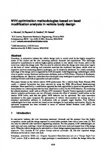
The schematic diagram of the
BleedAir to ECS COO19 Al
LOWPresurbie
Nz
two-spool, low-bypass, turbofan engine used as the basis for the PS is
l
Turbine
.Burne Splitter HIh, .r....re compressor I Duct I Duct I
HIl, ..... Turbine Duct i I
ruet
I I
Dct
in
descriptions
I
Low
LOWn pre~ssure Spool
shown
Afterburner Mixer
Figure
1
Detailed
I
of the physical
(i.e.
and dimensions), off-design,
pweight
heat transfer, and thermodynamic models used for the PS are found in
Figure 1. Turbofan engine components of the PS [9,5].
[9]. Turbine cooling is also incorporated into the engine analysis. Cooling air is drawn from the compressor exit with a portion used for cooling the high pressure turbine nozzle guide vanes and the remainder for cooling the high pressure turbine rotor. No cooling is included for the low pressure turbine. The model of the engine uses non-dimensional compressor and turbine performance maps to find the efficiencies at off-design conditions as a function of mass flow rate and pressure ratio, while mass, momentum and energy balances are used to model the thermodynamic behavior of the various components inside the PS. The model provides the thermodynamic properties (pressure, temperature, etc.) at each of the engine stations, the inlet air flow rate, nozzle areas, and the fuel consumed in the combustor and afterburner adjusted to provide the thrust required during the different segments of the mission. Assumptions made are as follow: steady flow; 1D flow at the entry and exit of each component and at each axial station; fan driven by a low pressure turbine, which also provides the mechanical power for accessories; high pressure bleed air and cooling air removed at the end of E-
the compressor; isentropic flow in the
C-
Sub-sý3 -h
%CY-.,
bypass duct; and completely mixed fan and core streams in the mixer.
......
1.3
A
ENVIRONMENTAL CONTROL SUB-SYSTEM (ECS) MODELS
"The ECS Figure 2. Schematic of an ECS bootstrap air cycle [9,51.
modeled.
here
is
a
conventional bootstrap system which provides conditioned air to the cockpit and
avionics. It is shown schematically in Figure 2. Air flow to the ECS is from pre-conditioned 3
bleed air. Flow into the ECS is varied by a pressure-modulating valve at the ECS inlet which also limits the maximum inlet pressure to the ECS's primary heat exchanger and bootstrap compressor. ECS performance is closely coupled with the PS and the aircraft flight conditions. Changes in the power settings cause changes in bleed air pressures and temperatures, which in turn affect the performance of the ECS. Detailed descriptions of the physical, geometric, heat transfer, and thermodynamic models for the ECS are given in [9,5]. 1.4
AIRFRAME-AERODYNAMICS SUBSYSTEM (AFS-A) MODELS The AFS-A shown in Figure 3 is defined as the empty aircraft, which includes fuselage,
wings, tail, gear, etc. but excludes the fuel weight, the PS weight, the ECS weight, and the payload. A master equation for flight
performance in terms of thrust loading
Lifi (L) Vclcit "
(TsL/WTO)
is
_
(
A~icfT M..
(u.Tl~usl..()
" ...[
-:
and wing loading (WTo/S)
derived
directly
from
. -
•....
... •Composite Drag (D) +
Additioonal Drag (R)
energy Wei gh (9)
considerations as a function of the
Figure 3. Force balance on the aircraft [9.5].
storage of potential and kinetic energy, respectively, due to changes in altitude (h) and aircraft velocity (u). If one assumes that the installed thrust is given by T = aTSL, where a is the installed full throttle thrust lapse, which depends on altitude and speed, and the instantaneous weight is given by w = IJWTO, where /l depends on how much fuel has been consumed and how much payload has been delivered, the master equation for flight is given by 7TSL= a {CDRD d {h+j} 2 g(1 ) +Iu dt .fWTo 8
(I
WTo
A complete description of the aerodynamic and geometric models for the AFS-A appears in [9,5]. 1.5
SYSTEM AND SUBSYSTEMS DESIGN OPTIMIZATIONS Five different optimization problems for the design of the AAF system are investigated and
the results compared. They are defined in the sections below for the thirteen segment mission (warm-up, takeoff acceleration, takeoff rotation, accelerate, climb, subsonic cruise climb 1, combat air patrol, supersonic penetration, combat turn, combat acceleration, escape dash,
4
subsonic Subs.onfi
Cr*utiseClimb
]Ewflpe
............... •D-....
~Deliv.er
/
cruise
--
2,
loiter)
depicted schematically in Figure 4
[9,5].
b; expencl'lbles
The five objectives,
defining
LitcrP....,uou Dcscend
climb
Comb,?•
-Subsonic Cruise Climb
a
different
each
optimization
problem are as follow:
ýdClimb
Co,,,t,,, A,
1. Obiective 1: minimization of
,
•.Vnrii -,tp
the gross takeoff weight; 2. Objective 2: minimization of
a,,,d Tekeonf
Figure 4. Schematic a the fourteen segment mission profile [9,5].
the total exergy destruction of the PS and ECS plus the total amount of unburned fuel exergy lost out the backend of the PS; 3.
Objective 3: minimization of the total exergy destruction of the PS and ECS as well as the exergy destruction due to the frictional losses associated with the parasitic drag the AFS-A plus the total amount of unburned fuel exergy lost out the backend of the PS; note that in [6-8], the exergy destruction due to the induced drag is also included;
4. Obiective 4: maximization of the thrust efficiency given by the ratio of the thrust work to the energy of the fuel used (both burned and unburned); 5. Obiective 5: maximization of the thermodynamic effectiveness [15] given by the ratio of the thrust work to the maximum thrust work which the PS could provide were no irreversibilities present in the PS and ECS and were all the fuel delivered to the engine burned; note that this measure, of course, ignores the exergy destruction due to parasitic drag in the AFS-A and must be updated to reflect this additional destruction when the AFS-A is optimized (allowed degrees of freedom,
Table 1. PS decision variables and inequality constraint limits [9]. Component
Decision Variables a
-
Fan
PRf.'
Compressor
PR.,.,p
Compesso PR,,.p Afterburner 7T, _________ ______
Fan bypass ratio
pressure ratio
Afterburner
-Temperature
decision
variables)
alongside the PS and ECS;
0.l_