Technical Institute, Lisbon, Portugal. ABSTRACT ..... Florida). Chen, Y. N. & Young, W. C., 1974, Damping. Capability of the Tube Band Against Vortex Ex$.
Flow Induced Vibration, Zolotarev & Horacek eds.
Institute of Thermomechanics, Prague, 2008
OPTIMIZATION OF BAFFLE CONFIGURATIONS TO PREVENT AEROACOUSTIC INSTABILITIES IN HEAT EXCHANGERS: PRELIMINARY EXPERIMENTS Miguel Moreira College of Technology, Setúbal, Portugal
José Antunes & Vincent Debut Institute of Nuclear Technology, Sacavém, Portugal
Heitor Pina Technical Institute, Lisbon, Portugal
ABSTRACT It is well known that gas heat exchangers are prone to aeroacoustic instabilities, which often lead to severe noise levels, structural vibrations and fatigue. These are unacceptable, as they threaten the component integrity and expose the plant workers to excessive noise levels. Such phenomenon is due to a cooperative interplay between the Karman vortices generated by the cross-‡ow and the heat exchanger acoustical modes (mainly those transverse to the tube banks). Energy exchanges are then such that, for certain operating velocities, self-excitation of one or more acoustical modes arises. Actually, this problem is solved by placing rigid ba- es inside the container, which modify the acoustic modal …elds and eventually inhibit the instability. However, an e¤ ective location of such ba- es is more or less di¢ cult depending on the system complexity and on the range of ‡ow velocities of interest. For realistic industrial components – using a restricted number of acoustical ba- es – their optimal location is a challenging problem, as trial and error experimentation is often a costly and frustrating procedure. In this paper we improve a recently proposed strategy for the optimal location of a given number of ba- es, in order to inhibit instability of the acoustical modes in a given frequency range. Our approach is based on a stochastic global optimization technique. Some preliminary experiments are also performed and compared with the simulation results. 1. INTRODUCTION Gas cross-‡ows through heat-exchanger tube arrays can severely excite acoustic modes often leading to severe noise levels, structural vibrations and fatigue. This phenomenon is been
studied by di¤erent authors during the last three decades, see, for instance, (Chen & Young, 1974; Fitzpatrick, 1985; Weaver & Fitzpatrick, 1987). Such phenomenon is mainly due to a cooperative interplay between the vortex-shedding generated by the cross-‡ow and the heat exchanger acoustical modes, mainly those transverse to the tube banks (Blevins, 1994). Basically the vortexshedding induced ‡uctuating lift forces (which are perpendicular to the direction of ‡ow and tube axes) can interact with the particle velocities of the ‡uid standing waves vibrating in the same direction (Eisinger & Sullivan, 2003). Energy exchanges are then such that, for certain operating velocities, self-excitation of one or more acoustical modes arises. So, an analysis of the ‡uid excitation forces and of the acoustic modal damping is of prime importance to predict the occurrence of this phenomenon. Unfortunately modeling the acoustic modal damping is a complex task depending on the relative importance of di¤erent dissipation mechanisms. These di¢ culties can be inferred from the compiled literature data showing a notorious dispersion among the representative stability / instability points (Blevins & Bressler, 1980; Laguerre, 1988; Eisinger et al., 1992). Recently Tanaka et al. proposed a new criterion to predict the occurrence of this phenomenon based in an energy balance between the energy of the sound pressure supplied by the ‡uid ‡ow and the energy consumed by the propagating sound waves (Tanaka et al., 1997; Tanaka et al., 1999). Distinct solutions has been proposed to suppress acoustic resonances (see, for instance, Eisinger, 1980; Blevins & Bressler, 1980; Blevins, 1994). Actually, this problem is solved by placing rigid ba- es — see Figures 1 and 2 — inside the container and parallel to the ‡ow stream, which modify the acoustic
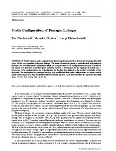
P
Tube bundles
D
P LB
LA
Direction of flow
LA LA
y( j )
LY
LA
Baffle x(i )
LA
LB
Figure 1: Test rig.
modal …elds and eventually inhibit the instability (see, for instance, (Eisinger & Sullivan, 2003; Eisinger & Sullivan, 2004; Fenstra & Weaver, 2004). Observe that, contrary to common belief and what has often been stated, typical ba- es only change acoustic frequencies marginally because the acoustic space remains connected upstream and downstream of them. Its main effect is to distort the acoustic modes decreasing the corresponding susceptibility to aeroacoustic instability (Eisinger & Sullivan, 2003). A general procedure, based on acoustic particle velocity mode shape functions, to evaluate the acoustic ba- e e¤ects was recently developed by Eisinger & Sullivan, 2003. This procedure involves the energy analysis of the oscillation energy provided by the vortex lift forces when the vortex shedding frequency approach modal frequencies, for both the original mode shapes of the system without ba- es and the acoustic mode shapes distorted by the ba- es, as well as the determination of the corresponding parameters extracted from experimental data. In this work we improve the functional F recently proposed (Moreira et al., 2006) to estimate the susceptibility to aeroacoustic instability of the various modes in a given frequency range. A simulated annealing (see, Moreira et al., 2007) procedure is then implemented to minimize F and obtain an appropriate M ba- e con…guration. Some preliminary experiments are performed and compared with the simulation results. 2. THEORETICAL CONSIDERATIONS Consider a rectangular ‡ow channel containing some tube banks shown in Figure 1, which represents a typical re-heater from a power station boiler. Following (Tanaka et al., 1997; Tanaka
L1
L2
L3
L5
L4
L6
L7
L8
L9
L10
L11
LX
Figure 2: Test rig: 2D-view of tube bundles in duct: orientation of axes and main dimensions; i and j are the modal indices fot acoustic modes.
et al., 1999), consider the forced modal acoustic pressure equations for a generic cavity p•n (t) + 2 n ! n p_n (t) + ! 2n pn (t) Z F:r'n dv ; n = 1; 2; : : : = c2 TZ 2 'n dv
(1)
V
where p^n (t; x; y) = pn (t) 'n (x; y) stands for nth modal acoustic pressure amplitude, F the acoustic forcing …eld, ! n the acoustic nth modal angular frequency, n the nth modal reduced damping and c is the sound velocity. Note that, for simple domains, the acoustical modes may be obtained analytically (apart from damping). For realistic heat-exchangers, the acoustic modes are computed using …nite elements (Cook et al., 2002). The acoustical e¤ects of the tube banks may be conveniently accounted using an equivalent sound velocity, as discussed later, obtained from an homogeneous model of the acoustic …eld (Parker, 1978). Note that integrations are performed in the interest regions, namely V is the complete acoustical domain and T is the subdomain occupied by the tube banks, where the vortex excitation arises. From (1) these authors deduced that, when the vortex generated forces are fully correlated with the acoustical mode 'n , one can express the modal forcing pressure source pn as Z (r'n )2 dv p n = Kn T Z ; n = 1; 2; : : : (2) '2n dv V
where Kn is an appropriate complex factor depending on the bundle geometry as well as the main ‡ow characteristics. Note that, for a straight rectangular duct with uniform ‡ow and acoustic conditions, it is well documented by experimental results that the vortex-shedding excitation correlates particularly well with the acoustical responses which are mainly transverse to both the tubes and the ‡ow. This fact justi…es why the acoustic modes typically excited by cross‡ow in tubular heat exchangers tube banks are transverse modes (see, Eisinger & Sullivan, 2003). Therefore, the forcing pressure source pn expression (2) will be here, tentatively, approximated as Z @'n 2 dv @y TZ p n Kn ; n = 1; 2; : : : (3) '2n dv V
This means that, in order to minimize the system susceptibility to aeroacoustic instability we must minimize (3), in a given frequency range (related to the Strouhal shedding frequencies excited by the ‡ow velocity of interest), say 1 ! n 2; using an optimal con…guration of a given number of ba- es in the ‡ow channel. Notice that most of the complex physics of the vortex excitation and aeroacustic interaction are encapsulated in the modal parameters Kn . For their determination one usually has to perform extensive experimentations, as they are in general frequency dependent complex quantities. Here, however, we will assume for simplicity that the acoustical mode shapes are a dominant factor which controls the acoustical modal susceptibility to aeroacoustic instability supposing additionally that Kn 1=! 2n . From the above-mentioned arguments one may propose the following improved (see, Moreira et al., 2006) functional to minimize F fBi , i = 1; : : : ; M g 9 8Z 2 @' > > n > > dv = < @y T Z ; n = 1; 2; : : : (4) = max n > > > > ; : ! 2n '2n dv V
over the appropriate frequency range of interest, !n 1 2 . Here, integrations are respectively, performed in the tube banks region (T region) or in the complete domain (V -region), respectively. Observe that {Bi , i =1,. . . ,M } stands for a given M ba- e con…guration, which distorts the pressure mode shapes in the frequency range of interest.
3. OPTIMIZATION STRATEGY The minimization of functional (4) involves the computation of the modal frequencies and cavity pressure mode shapes for each given M ba- es con…guration. This task is performed with a set of algorithms developed by the authors using the Matlab PDE Toolbox (Partial Di¤erential Equation Toolbox) which automatically generates the geometry and the …nite element mesh (corresponding to the given M ba- es con…guration) and then computes the modes from the Helmholtz equation. The boundary conditions used are Neumann in the axial walls and Dirichlet at the inlet and outlet of Z the duct. Then @'n 2 dv and for each mode we compute @y T Z '2n dv in order to …nd the excitation susceptiV
bility function F {Bi , i =1,. . . ,M } in the given frequency range of interest. For minimization of (4), we adopted the basic simulated annealing strategy described in Press et al., 1997, based in the Metropolis algorithm (Metropolis et al., 1953). Roughly speaking, simulated annealing is a global minimization strategy based on an analogy to the annealing of metals, in which a slow cooling (anneal) of a previously heated metal gives it more chances of …nding structure con…gurations with lower internal energy than the initial one. The algorithm consists in, for a given M ba- e con…guration {Bi , i = 1,. . . ,M } and for an appropriately choosed temperature T; generate a random perturbation of the positions of the M ba- es. The new perturbed M ba- e con…gue i , i =1,. . . ,M } will be accepted as betration {B ter than the original one if F {Bi , i =1,. . . ,M } e i , i =1,. . . ,M }. If F {Bi , i =1,. . . ,M }< F {B ei , F {B i =1,. . . ,M } the new perturbed M ba- e con…ge i , i =1,. . . ,M } will be accepted with a uration {B probability p, computed as p = exp
e i , i =1,. . . ,M } F {B
F {Bi , i =1,. . . ,M } T
(5) Therefor, local minima may be overcome through (5). Notice that, the probability of acceptance worst solutions decrease as temperature T is lowered, so that the algorithm progressively focus on a narrower search domain. Generically, it can be shown that the iteration of this strategy for any given …nite problem, using an in…nitely slow decreasing temperature schedule T; generates a sequence of con…gura-
!
:
tions which approach a global optimal solution (see for instance, Arst & Korst, 1989). However, in practical implementations of simulated annealing, …nding a global optimal solution (in a …nite time) is not guaranteed in general. Nevertheless, as in many other …elds, our implementation proved successful and well suited in the context of the problem addressed here.
f;g f[83; 163; 117; 119]g [85; 165; 117; 119] [154; 234; 87; 89]
F = 2103 minfF g = 1748 minfF g = 1505
Table 2: Numerical simulations: susceptibility data and optimum geometric locations of ba¤ es (in mm).
4. NUMERICAL RESULTS All the performed numerical computations were based on the rectangular ‡ow channel schematically represented in Figure 2. The main geometric parameters are shown in Table 1, pertaining to an experimental rig currently under testing (see Figure 1). Observe that the position of tube bundles are de…ned by the tabulated parameters L1 ,. . . , L11 . LX [m] 0:414 L3;5;7 [m] 0:014 LA [m] 0:030
LY [m] 0:206 L6 [m] 0:056 LB [m] 0:028
L1 [m] 0:096 L9 [m] 0:05 P [m] 0:010
L2;4;8;10 [m] 0:026 L11 [m] 0:066 D [m] 0:006
b)
Table 1: Main geometrical parameters.
c)
As discussed before, the estimation of the sound velocity c in regions with tubes was based in the corrective expression (see, for instance, Blevins & Bressler, 1980) c = c0 p
1 ; 1+
a)
(6)
where c0 is the sound velocity in air and = 2 . Note that the tabulated D and P 0:7853 D P values stand for the tube diameter and pitch for the corresponding square-arranged tube banks. The ba- es used in computations are 0:08 m long and 0:002 m thick. Note that, the possible y coordinate positions of the ba- es were de…ned by the tabulated LA and LB values. This means that the possible con…guration space of a given M ba- es is discrete in the y direction. In order to be able to address a signi…cant number of higher order transverse modes we choosed the frequency range of interest to be 0 2000 Hz. In Table 2, we display the reference value of the susceptibility function (4), for our system with no ba- es F f;g ; as well as the corresponding ba- e
Figure 3: Acoustic mode shapes of the frequencies with largest susceptibility with respect to the corresponding con…guration: 0, 1 and 2 ba- es.
locations and values of the minimized susceptibilities using 1 and 2 ba- es. In Figure 3 a) we display the acoustic mode shape of the frequency with largest susceptibility for our system with no ba- es. In Figures 3 b) and 3 c) we display the corresponding acoustic mode shapes of the frequency with largest susceptibility with respect to the corresponding computed optimum con…guration. Observe, in …rst place, that the susceptibility function F decreases when the number M of optimum located ba- es is increased as it should (see, Table 2). The largest modal susceptibility with respect the corresponding con…guration occur in the …rst transverse pressure mode shape at 824 Hz [see,
were modi…ed by the presence of the …rst ba- e less than 10%:
Autospectre [dB]
Autospectre [dB]
Autospectre [dB]
Vel. int. = 20 m/s 100 a)
--> 824 Hz
50
6. CONCLUSIONS
0 Baffles; Leq=103.5 dB 0 0
200
400
600
100 b)
800
1000
1200
1400
1600
1800
2000
--> 785 Hz
50
1 Baffle; Leq=91.6 dB 0 0
200
400
600
800
1000
200
400
600
800
1000
1200
1400
1600
1800
2000
1800
2000
100 c)
50
2 Baffles; Leq=84.2 dB 0 0
1200
1400
1600
Frequency [Hz]
Figure 4: Autospectra of our system with 0 Baf‡es, 1 Ba- e and 2 Ba- es (for an intertube speed of 20 m/s).
Figure 3 a)]. One can note the distorting e¤ects, of the ba- es, over the mode shapes modifying the orientation of the transverse components of the acoustic pressure gradient (see, Figures 3 b) and 3 c). One can estimate that the corresponding frequencies were modi…ed by the ba- es 10% 20%. This fact is in agreement with Eisinger et al., 2003. 5. EXPERIMENTS Experiments were performed in the test rig shown in Figure 1. The working ‡uid is air ‡owing through our test rig with an intertube speed of about 20 m/s. The acoustical pressure amplitude p and frequency f are measured at the open outlet of the test rig by means of a sound level meter Brüel&Kjaer type 2221. The transmitter output is connected to the port of a Spectral Dynamic acquisition board (Model 20-42) which ensures the analog digital conversion. In Figure 4 we display the autospectra of our system for the intertube air speed of 20 m/s, with no ba- es as well as 1 and 2 ba- es localized in the optimum positions displayed in Table 2. We observe that the noise level Leq decreases (0 ba- es: 103:5 dB; 1 ba- e: 91:6 dB; 2 baf‡es: 84:2 dB) when the number M of optimum located ba- es is increased showing that the instability occurring at 824 Hz [see Figure 4 a)] was e¤ectively inhibited [see Figure 4 c)]. Note also that the frequency of the unstable mode shape
In this paper we presented a systematic approach to optimize M -ba- e con…gurations, in order to inhibit aeroacoustic instabilities in heat exchanger tube banks caused by vortex shedding. A stochastic global optimization method has been implemented to compute optimal ba- e locations, in order to minimize a given functional which re‡ects the system susceptibility to aeroacoustic instabilities. A tentative con…guration-dependent functional recently adopted was improved. This functional (see, Moreira et al. 2006) was based on physical ideas borrowed from Tanaka et al., 1997 and Eisinger & Sullivan, 2003. The spatial aspects of the force …eld and of the acoustic modes - assumed totally correlated when aeroacoustic instability arises - have been considered the dominant factor which triggers (or not) the unstable behavior. Additionally the complex physics of the vortex excitation and aeroacustic interaction, considered encapsulated in the modal parameters Kn , was assumed satisfying Kn 1=! 2n . A realistic test case was presented, for which the optimal ba- e con…gurations - using 1 and 2 ba- es - were computed. The results obtained when no ba- es are used were compared with those stemming from the optimal ba- e con…gurations. They clearly show a signi…cant decrease of the system modes susceptibility to aeroacoustic instabilities when one or more baf‡es are optimally located. Furthermore, as expected, such susceptibility further decreases as the number of ba- es is increased. The theoretical results obtained was compared with preliminary experiments showing a satisfactory agreement. Indeed, the proposed approach present an obvious interest, both as a tool for designing quiet heat exchangers as well as for …xing problems in actual components. 7. ACKNOWLEDGMENTS We would like to express our acknowledgments to John Aidan Fizpatrick by the interesting discussions and suggestions concerning this work. A very special thanks goes out to Martins Paulino by making possible our test rig to perform all experiments. This project has been endorsed by the Portuguese FCT and POCI 2010, with funding par-
ticipation through the EC programme FEDER. 8. REFERENCES Aarts E. H. L. & Korst, J., 1989, Simulated Annealing and Boltzmann Machines, (John Wiley & Sons). Blevins, R. D., & Bressler, M. M., 1980, Acoustic Resonance in Heat Exchanger Tube Bundles, Journal of Pressure Vessel Technology, 102, 138145. Blevins, R. D., 1986, Acoustic modes of Heat Exchanger Tube Bundles, Journal of Sound and Vibration, 109, 19-31. Blevins, R. D., 1994, Flow-induced vibration, (Krieger Publishing Company, Malabar, Florida). Chen, Y. N. & Young, W. C., 1974, Damping Capability of the Tube Band Against Vortex Excited Sonic Vibrations, Journal of Engineering for Industry, 96, 1072-1075. Cook, R. D., Malkus, D. S., Plesha, M. E., & Witt, R. J., 2001, Concepts and Applications of Finite Element Analysis-4th Edition (John Wiley & Sons, Inc.). Eisinger, F. L., 1980, Prevention and Cure of Flow-Induced Vibration Problems in Tubular Heat-Exchangers, ASME Journal of Pressure Vessel Technology, 102, 138-145. Eisinger, F. L., Sullivan, R. E. & Francis, J. T., 1992, A Review of Acoustic Vibration Criteria Compared to In-service Experience with Steam Generator In-Line Tube Banks, Proceedings of the ASME Pressure Vessel and Piping Conference, Symposium on Flow-induced Vibration and Noise, Anaheim, November 8-13. Eisinger, F. L. & Sullivan, R. E., 2003, Suppression of Acoustic Waves in Steam Generator and Heat Exchanger Tube Banks, Journal of Pressure Vessel Technology, 125, 221-227. Eisinger, F. L. & Sullivan, R. E., 2004, Evaluation of Acoustic Resonance in Tubular Heat Exchangers and its Suppression, Proceedings of the FIV2004, 1, 423-428. Feenstra, P. A. & Weaver, D. S., 2004, The Effects of Duct Width and Ba- es on Acoustic Resonance in a Staggered Tube Array, Proceedings of the FIV2004, 1, 459-464. Fitzpatrick, J. A., 1985, The Prediction of FlowInduced Noise in Heat Exchanger Tube Arrays, Journal of Sound and Vibration, 99, 425-435. Laguerre, J., 1988, Étude des Instabilités Acoustiques dans les Échangeurs de Chaleur à Faisceaux Tubulaires en Écoulement Transverse
Gazeux, Thèse de Docteur 3e cycle, Université de Marseille. Metropolis, N. , Rosenbluth, A., Rosenbluth, M., Teller, A. & Teller, E., 1953, Equation of State Calculations by Fast Computing Machines, Journal of Chem. Phys., 21, 1087-1092. Moreira, M., Antunes, J., Paulino, M., Debut, V. & Pina H., 2006, Optimization of ba- e con…gurations to prevent aeroacoustic instabilities in heat exchangers: a preliminary study, Proceedings of the Internoise 2006, paper 318, Honolulu, Hawaii, USA. Moreira, M., Antunes, J., Pina H. &Debut, V., 2007, Optimization of ba- e con…gurations: A genetic algorithm versus a simulated annealing approach, Optimization 2007, Porto, Portugal. Parker, R., 1978, Acoustic Resonances in Pasages Containing Banks of Heat Exchangers Tubes, Journal of Sound and Vibration, 57, 245-260. Press, W. H., Teukolski, S. A., Vertterling, W. T. & Flannery, B. F., 1994, Numerical Recipes in C - The Art of Scienti…c Computation, (Cambridge University Press). Tanaka, H., Matuzoe, J., Tanaka, K. & Shimizu, F., 1997, Analysis of Acoustic Resonant Vibration Having a Mutual Exciting Mechanism, Proceedings of the 4th International Symposium on Fluid-Structure Interactions, Aeroelasticity, Flow-Induced Vibration and Noise, Texas, November 16-21, AD-Vol. 53, 339-346. Tanaka, H., Tanaka, K., & Shimizu, F., 1999, Analysis of Acoustic Resonant Vibration Having a Mutual Exciting Mechanism (Application to a Real Plant), Proceedings of the ASME Pressure Vessel and Piping Conference, Symposium on Flow-induced Vibration and Noise, Boston, August 1-5, PVP-Vol. 389, 145-152. Ziada, S. & Oengören, A., 1992, Vorticity Shedding and Acoustic Resonance in In-Line Tube Bundle, Journal of Fluids and Structures, 6, 271309. Weaver, D. S. & Fitzpatrick, J. A , 1987, A Review of Flow Induced Vibrations in Heat Exchangers, Proceedings of the Flow Induced Vibration, Bowness-on-Windermere, England, May 12-14, 1-17.