Optimization of Distributed Generation on the Nigerian Electrical Grid Ariyo, Funso K.
Fatunmbi, Rereloluwa O.
Lasabi, Olanrewaju A.
Omoigui, Michael O.
(Prof.) Department of Electronic and Department of Electronic and Department of Electronic and Electrical Engineering Electrical Engineering Electrical Engineering Department of Electronic and Obafemi Awolowo University Obafemi Awolowo University Obafemi Awolowo University Electrical Engineering Ile-Ife, Nigeria Ile-Ife, Nigeria Ile-Ife, Nigeria Obafemi Awolowo University
[email protected] [email protected] [email protected] Ile-Ife, Nigeria
[email protected] Abstract— This paper presents the transient stability analysis of the Nigerian Power Grid with added Distributed Generation (DG) at various levels of penetration. A transient fault is introduced to a particular bus and the effect of this on generator rotor angle and system frequency is determined. PV curves are also obtained for the various penetration levels in consideration in order to ascertain voltage stability. The optimum penetration level of DG in Nigeria is then determined based on these outcomes. In this work, DG is limited to wind and solar power. The choice of location of distributed generation is also a very important factor in planning for the expansion of the power system. Recent research has shown that improper placement of distributed generators on a power network could jeopardise system performance. Hence, by the use of artificial intelligence, specifically Fuzzy Inference System, the optimum location of distributed generation units is determined. Based on this research work, a software package has been designed to guide power system planners to ascertain if a given location is suitable for installation of wind or solar power plants. Index Terms—Distributed generation, centralized power, fuzzy inference system, power flow, irradiation level, wind pattern, power system stability, transient fault, PSAT, PowerWorld, Matlab, penetration level, rotor angle, membership functions.
I. INTRODUCTION As a result of global environmental pollution with consequent global warming and unpredictable price of oil, there is increasing interest in Renewable Energy. Recent trends reflect the need for developing countries to focus on renewable energy technologies and to seriously consider Distributed Generation (DG) as a viable alternative to the conventional means of power generation. Energy demand in Nigeria is growing rapidly and this trend is likely to continue. However, Nigeria’s energy mix consists of mostly non-renewable schemes. Considering her varied and inexhaustible renewable energy resources, as well as global challenges aforementioned, it is imperative that Nigeria considers Distributed Generation option. The current model for electricity generation and distribution in Nigeria is dominated by centralized power plants (thermal and hydro) on an interconnected system (National Grid). The generating centres
978-1-4673-4568-2/13/$31.00 ©2012 IEEE
are far away from the actual users of the power generated, so there is a need to transmit power across long distances. This kind of system has many disadvantages; it contributes to greenhouse gas emission, there exist inefficiencies and power loss over the lengthy transmission lines, environmental impact where the power lines are constructed, and security related issues. Hence, there is a need for Distributed generation. With high degrees of dispersed generation penetration, grid operators will probably need more flexibility than they have today. If managed properly and with real time regulation function considering current load level, DGs will be able to lower their generation capacity and also can provide voltage support capability [1]. Distributed Generation is an approach that employs smallscale technologies to produce electricity close to the end users of power. In many cases, distributed generators can provide lower-cost electricity and higher power reliability and security with fewer environmental consequences [2]. DG systems employ numerous, but small plants and can provide power onsite with little reliance on the distribution and transmission grid. DG technologies yield power in capacities that range from a fraction of a kilowatt (kW) to about 100 megawatts (MW). Traditionally, distribution network design did not need to consider stability as the network was passive and remained stable under most circumstances provided the transmission network was itself stable. Even at present, stability is hardly considered when assessing renewable distributed generation schemes. However, this is changing as the penetration of these schemes increases and their contribution to network security becomes greater [3]. To maximize the benefits of DG technology, it is crucial to find the optimal number or size of DG units and their appropriate locations in power distribution systems. It should be noted that DG would lead to increase in loss only when it is sited in improper locations [4]. II. WIND AND SOLAR PATTERN IN NIGERIA Earlier, it was established that the current mode of power generation in Nigeria which comprises of only conventional generators is fraught with demerits some of which have already been outlined. This is where DG technology comes useful. However, in order to determine the impact of DG on the power
885
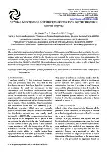
network, it is important to first ascertain the viability of DG technology in Nigeria. Since the scope of this work is limited to Wind and Solar energies, the prospects of DG in Nigeria power system will be limited to these two aspects. Figure 1 shows the wind speed pattern in Nigeria. The energy from wind is strongly dependent on the average wind speed in the location where the wind energy conversion system is to be sited. In addition, the availability and consistency of this wind speed are essential in order to determine the economic viability of wind energy. In siting wind energy conversion system, the first major step is to determine the characteristics of the wind speed at the targeted site and estimate the amount of energy that can be derived from such wind speed [5]. For investment on wind energy conversion system to be cost effective [6], the site average wind speed should be between 4 and 6 m/s [7]. On a nationwide scale, utilization of wind energy resources for electricity generation can only be achieved and be cost effective in limited locations such as Gausau, Jos, Kano and Sokoto. These areas have average annual wind speeds of more than 6 m/s [8]. Other potential areas for electricity generation are Kaduna, Potiskum, Maiduguri, Ilorin, Minna and Enugu with wind average annual wind speeds in the range of 5-6 m/s. Except for Enugu which is in the south, all these locations are in the northern part of the country [5]. The energy transferred from the sun in the form of radiant energy to the earth’s surface is normally referred as the solar radiation [9]. In any solar energy conversion system, the
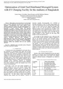
knowledge of global solar radiation is germane for the optimal design and prediction of the system performance [10]. Most of the photovoltaic (PV) systems that are currently in use such as PV modules for street lighting are government sponsored projects. Some are pilot projects sponsored by government agencies. In any solar energy conversion system, the knowledge of global solar radiation is germane for the optimal design and prediction of the system performance [9]. The photovoltaic (PV) systems are also currently employed to provide electricity service to rural communities that are not connected to the country’s electricity grid. Figure 2 shows the irradiation pattern of Nigeria. This data is used in the Fuzzy Inference System (FIS) structure to determine the optimum location of DG on the grid. III. METHODOLOGY This research centres on optimization of DG on the Nigerian power grid. The effect of DG with respect to power system stability is determined in order to derive the optimum penetration level of DG on the Nigerian power grid. Then with the use of Fuzzy Inference System, the optimum location for DG is ascertained. A. Modelling the Nigerian Power Grid A proper dynamic modelling of the power network for dynamic behaviour studies is a key issue to get adequate idea of the impact on the network resulting from the presence of
Fig.1. Predicted monthly average wind speeds (m/s) distribution (isovents at 10m height) in Nigeria for the month of June [8]
886
relative importance of precision: How important is it to be exactly right when a rough answer will do? Its flexibility and
Fig. 2. Irradiation Pattern of Nigeria
these generation units following some disturbances [11]. First the Nigerian 330kV grid, as it is today, is simulated on PowerWorld and PSAT simulators. The oneline diagram of the national grid is shown in figure 3. The power flow is solved with the use of Newton-Raphson method. This method is found to be more efficient and practical when compared with other methods [12]. The results obtained from these two software packages are compared for consistency. Next DG is placed on the grid at various penetration levels. Penetration level is the ratio of active power injected to load capacity of the network [13]. The mathematical expression is given by: Penetration Level (%) =
(∑ P
DG
∑ P )x100 L
(1)
where PDG = Total MW power from DG and PL = Total Load Demand in MW. To examine the impact of DG, the following penetration levels are considered in the system under study: • Case I: 0 % of total load demand (No DG) • Case II: 5 % of total load demand (215.9735MW) • Case III: 10 % of total load demand (431.947 MW) • Case IV: 15 % of total load demand (647.9205MW) • Case V: 20 % of total load demand (863.894MW) B. Fuzzy Inference System Fuzzy logic is one of the successful applications of the control engineering field which can be used to control various parameters of real time systems. Fuzzy logic is all about the
ability to model non-linear systems of arbitrary complexity is what makes fuzzy logic a good alternative to determine the optimum siting of DG. Besides, fuzzy logic can be built on top of the experience of experts [14]. Fuzzy Logic Toolbox is used to design the structure for optimum siting of distributed generation on the Nigerian power network. Fuzzy Logic Toolbox provides Matlab functions, graphical tools, and a Simulink block for analyzing, designing, and simulating systems based on fuzzy logic. The steps taken in designing the required fuzzy structure are: 1. Define the input(s) and output(s): In this work, the inputs to the system will depend on the type of DG to be considered. For wind, the inputs will be the desired location for DG installation, wind speed, the penetration level and the total power losses. For solar, the inputs will be the desired location for DG installation, irradiation level, the penetration level and the total power losses. In both cases, the output will be the extent to which this location is suitable for DG placement. 2. Fuzzify the inputs: This is to take the inputs and determine the degree to which they belong to each of the appropriate fuzzy sets via membership functions. 3. Define the rules to guide the mapping of inputs to the output and apply fuzzy operator to the rules. Apply implication method to each rule to get an output. 4. Aggregate the outputs of each rule. Aggregation is the process by which the fuzzy sets that represent the
887
Gombe 216 MW 109 Mvar
DG2
7 MW
-69 Mvar
20 Mvar
131 MW
53 Mvar 200 MW
193 M W
409 MW
216 MW
DG1
70 MW
Kano
431 MW
98 Mvar
488 Mvar
150 Mvar
145 Mvar
52 MW
Jos
5 Mvar
Kainji GT
Birnin
39 Mvar
Kainji
Kaduna
320 MW
115 MW 86 Mvar
178 MW
256 Mvar
Jebba GT -36 Mvar
N-Haven
Shiroro
Alaoji
shiroro GT
JebbaG
Ajaokuta
151 Mvar
276 MW
633 MW
207 Mvar
475 Mvar
185 MW
138 Mvar
14 MW
383 MW 288 Mvar
Osogbo
427 MW 320 Mvar
Onitsha
173 MW 181 Mvar
Jebba
201 MW
Afam
133 Mvar
11 MW 8 Mvar
495 MW
Afam GT
10 Mvar
Benin
Sapele Sapele GT 0 MW
Ayede
IkejaWt
302 Mvar
Delta 21 MW 15 Mvar
Akangba Delta GT 345 MW
259 Mvar
Aja
Egbin GT 1665 MW 851 Mvar
274 MW 206 Mvar
Aladja
670 MW
97 MW
32 Mvar
72 Mvar
69 MW Egbin
52 Mvar
Fig. 3. One line diagram of the Nigerian Power Network (330kV)
outputs of each rule are combined into a single fuzzy set. 5.
Defuzzification: The input to the defuzzification process is the result of the aggregation done earlier and the output is a single number. The defuzzification method to be used in this study is the centroid method given by:
z∗ =
where
∫ µ ( z) ∗ zdz ∫ µ ( z )dz
z ∗ = resultant location status µ (z ) = output membership function z = location status
IV. RESULTS AND DISCUSSION Having employed the procedures enumerated in the previous section, the results obtained are properly analyzed and presented as follows.
A. Optimum Penetration Level The objective of this section is to present the research results of the impact analysis of different DG penetration levels on the basis of transient stability and voltage stability of the Nigerian grid under a solid three-phase fault on a selected bus. The fault is applied to the Ajaokuta bus for 20 milliseconds. A major bus, the Benin bus is then observed at the various penetration levels mentioned earlier. Modelling and simulations of the case study power network are carried out on PowerWorld simulator and PSAT. The DGs are placed on the Gombe and Kano buses. Several power flow studies were carried out prior to the choice of these buses. They are the buses that give minimum total power loss on the system when DGs are placed in them. Besides, the wind speed and irradiation levels at the location of these buses are acceptable. For frequency stability, the Benin 330kV bus is considered. Shiroro hydro generator is used to determine rotor angle transient stability. A solid fault is applied to Ajaokuta bus for 20 milliseconds. The total simulation time spans 30 seconds with a time step of 0.5 cycles.
888
These results are shown graphically in figures 4 to 13. Figures 4, 5, 6, 7 and 8 show the responses of Shiroro generator rotor angle to the transient solid three-phase fault at the Ajaokuta bus at 0%, 5%, 10%, 15%, 20% penetration levels respectively. Comparing these figures, it is observed that the rotor angle oscillation for all the cases eventually wanes. However, of all the scenarios considered, the 10% penetration level has the best profile; after about 15 seconds, the oscillation for this case dies out as shown in figure 6. It is also glaring from the result shown in figure 4 that at 0% when there is no DG connected to the grid, the generator’s rotor angle still keeps undulating for a long time frame. This shows that DG can improve the rotor angle stability of the conventional generators tied to the Nigerian grid. However, if the penetration level is excessive, the power system stability is seriously threatened as shown in figures. 12 and 13 which show the frequency undulations for 15% and 20% penetration levels respectively.
Results for voltage stability analysis are obtained from the PV curves (figure 14). The knee of the PV curve is the critical point of the system which when exceeded, voltage drops rapidly (collapse margin). The knee is where the stability ends and voltage collapses. The curve with the widest stretch, before the knee is reached shows the system with highest steady state stability. The plot confirms the inference from the earlier obtained results that 10% penetration level is the optimum. The graph shows that the critical voltage at 10% penetration level is reached after an active power value of 1.68pu. At other penetration levels the critical voltage is reached at lower p.u values which shows they are not as voltage stable as 10% level. 10% penetration level has the highest collapse margin and hence, the highest voltage stability index.
9 8.5 8 GenshiroroGT#1R otor Angle
Generator rotor angle (degrees)
Gen s hiroro GT #1 Rotor Angle
7.5 7 6.5 6 5.5 5 4.5 4 3.5 3 0
1
2
3
4
5
6
7
8
9
10 11 12 13 14 15 16 17 18 19 20 21 22 23 24 25 26 27 28 29 30 Time
Time (s)
Gen shiroro GT #1 Rotor A ngle
Fig. 4. Response of Shiroro generator rotor angle to transient fault (0% penetration level) Ge n s hir or o GT #1 Rotor Angle 28
27 26.5 26 G enshiroroG T#1R otor A ngle
Generator rotor angle (degrees)
27.5
25.5 25 24.5 24 23.5 23 22.5 22 21.5 21 20.5 20 19.5 0
1
2
3
4
5
6
7
8
9
10 11 12 13 14 15 16 17 18 19 20 21 22 23 24 25 26 27 28 29 30 Time
Time (s)
Gen s hiroro GT #1 Rotor Angle
Fig. 5. Response of Shiroro generator rotor angle to transient fault (5% penetration level)
889
G enshiroroG T#1Rotor Angle
Generator rotor angle (degrees)
Ge n s hiror o GT #1 Rotor Angle 19.5 19 18.5 18 17.5 17 16.5 16 15.5 15 14.5 14 13.5 13 12.5 12 11.5 11 10.5 10 9.5 9 0
1
2
3
4
5
6
7
8
9
10 11 12 13 14 15 16 17 18 19 20 21 22 23 24 25 26 27 28 29 30 Time
Time (s)
Gen shiroro GT #1 Rotor Angle
Fig. 6. Response of Shiroro generator rotor angle to transient fault (10% penetration level) Ge n s hiroro GT #1 Rotor Angle
53 52 51 G ensh iroroG T#1R o to rA n g le
Generator rotor angle (degrees)
54
50 49 48 47 46 45 44 43 42 41 40 0
1
2
3
4
5
6
7
8
9
10
11
12
13 14 15 16 17 Time
18
19
20
21 22 23 24
25
26
27 28 29 30
Time (s)
Gen shiroro GT #1 Rotor A ngle
Fig. 7. Response of Shiroro generator rotor angle to transient fault (15% penetration level)
G enshiroroG T#1RotorA ngle
Generator rotor angle (degrees)
Ge n s hiroro GT #1 Rotor Angle -24 -26 -28 -30 -32 -34 -36 -38 -40 -42 -44 -46 -48 -50 -52 -54 -56 -58 -60 -62 -64 -66 -68 0
1
2
3
4
5
6
7
8
9
10 11 12 13 14 15 16 17 18 19 20 21 22 23 24 25 26 27 28 29 30 Time
Time (s)
Gen s hiroro GT #1 Rotor A ngle
Fig. 8. Response of Shiroro generator rotor angle to transient fault (20% penetration level)
890
Bus Be nin Fr e que ncy 50.09 50.08 50.07
Bus frequency (hertz)
50.06
B usB eninFrequency
50.05 50.04 50.03 50.02 50.01 50 49.99 49.98 49.97 49.96 0
1
2
3
4
5
6
7
8
9
10 11 12 13 14 15 16 17 18 19 20 21 22 23 24 25 26 27 28 29 30 Time
Time (s)
Bus Benin Frequency
Fig. 9. Response of Benin bus frequency to transient fault (0% penetration level)
Bus Be nin Fre que ncy 50.09 50.08
50.06 50.05 B usB eninFrequency
Bus frequency (hertz)
50.07
50.04 50.03 50.02 50.01 50 49.99 49.98 49.97 49.96 0
1
2
3
4
5
6
7
8
9
10 11 12 13 14 15 16 17 18 19 20 21 22 23 24 25 26 27 28 29 30 Time
Time (s)
Bus Benin Frequency
Fig. 10. Response of Benin bus frequency to transient fault (5% penetration Bus Be nin Fr e que ncy
50.085 50.08 50.075 50.07 50.065 50.06 50.055
B u sB e n inF re q u e n cy
Bus frequency (hertz)
50.09
50.05 50.045 50.04 50.035 50.03 50.025 50.02 50.015 50.01 50.005 50 49.995 49.99 49.985 49.98 49.975 49.97 49.965 49.96 0
1
2
3
4
5
6
7
8
9
10 11 12 13
14 15 16 Time
17 18 19 20
21 22 23 24
Bus Benin Frequency Time (s)
level) Fig. 11. Response of Benin bus frequency to transient fault (10% penetration level)
891
25 26 27 28
29 30
Bus Be nin Fr e que ncy 50.05
50.04 50.035 50.03 B u sB e n inF re q u e n cy
Bus frequency (hertz)
50.045
50.025 50.02 50.015 50.01 50.005 50 49.995 49.99 49.985 0
1
2
3
4
5
6
7
8
9
10 11 12 13
14 15 16 Time
17 18 19 20
21 22 23 24
25 26 27 28
29 30
Time (s)
Bus Benin Frequency
Fig. 12. Response of Benin bus frequency to transient fault (15% penetration level) Bus Be nin Fr e que ncy 50.05 50.045
50.03 50.025 B usB eninFrequency
Bus frequency (hertz)
50.04 50.035
50.02 50.015 50.01 50.005 50 49.995 49.99 49.985 49.98 49.975 49.97 49.965 49.96 49.955 0
1
2
3
4
5
6
7
8
9
10 11 12 13 14 15 16 17 18 19 20 21 22 23 24 25 26 27 28 29 30 Time
Time (s)
Bus Benin Frequency
Fig. 13. Response of Benin bus frequency to transient fault (20% penetration level)
1.006
0% PL (no DG) 5% PL 10% PL 15% PL 20% PL
1.004
V o lt a g e ( p . u . )
1.002 1 0.998 0.996 0.994 0.992 0.99 0.988 0
0.2
0.4
0.6
0.8
1
1.2
1.4
1.6
Active Power (p.u.) Fig. 14. PV Curves at the various penetration levels
1.8
B. Optimum Location of DG on Nigerian Grid The objective functions that are considered to establish the optimum siting of Distributed Generation on the Nigerian grid are: i. Transient stability of the system. ii. Voltage stability: maintaining the voltage within the permissible limits. iii. Minimizing the total real power loss. iv. Type of DG technology to be installed (The scope of this work is limited to solar and wind. Hence the solar and wind data of Nigeria are used to calibrate this system). The DG optimization software designed for siting of DG on the Nigerian grid is shown in figure 15. The software is designed in the Matlab language. A user enters a prospective location for DG (solar or wind) installation. Based on fuzzy logic, the software computes the suitability of this location. The software package is designed to determine optimum location of DG as well as the extent to which any particular location in Nigeria is suitable for siting DG (solar or wind or
892
established. The IF-THEN rules used to set up this system were written based on the aforementioned criteria. From the obtained results a software was developed to assist power system planners decide on what location(s) are most suitable for siting of solar and wind power plants. REFERENCES
Fig. 15. Graphical User Interface of DG Optimization Software
both). The user enters the proposed number of the bus as well as the desired penetration level in textboxes. There is also a textbox for the losses. Losses data can be obtained after the grid has been simulated on Powerworld. Based on these inputs, the software uses fuzzy logic, based on predefined membership functions and rules to determine the suitability of the location. The software also displays the bus name, wind speed, irradiation level of the bus number inputted. From the results, Jos is the most suitable location for siting both solar and wind plants when it runs at a penetration level of 10% of total power demand. CONCLUSION The effect of DG on power system stability of the Nigerian grid was evaluated in this work on the basis of steady state stability (voltage stability) and transient stability (rotor angle and frequency stabilities). This was observed at various levels of DG penetration. Based on the results obtained in this research, it is concluded that for the Nigerian grid, a DG penetration level of 10% is the optimum. Comparing the results obtained in this work with results of earlier works that determined the optimum penetration level based on power loss, this work proves that there is no universal optimum penetration level that can be applied to any power network. The optimum level of DG penetration is actually a function of the power grid in consideration. For the Nigerian grid, 10% DG penetration level gives the optimum results. Through the use of fuzzy inference system calibrated in the light of the wind speed and solar irradiation patterns in Nigeria, taking power losses and stability into consideration, the optimum locations of distributed generation in Nigeria was
[1] Tlusty J. and Vybiralik F., “Management of the voltage quality in the distribution system within dispersed generation sources”, 18th International Conference on Electricity Distribution, Turin, 2005. [2] World Alliance for Decentralized Energy (WADE). “How decentralised energy can deliver cleaner, cheaper and more efficient energy in Nigeria”. Christian Aid and the International Centre for Environment and Energy Development (ICEED). K. Elissa, Ed, unpublished pp. 8, 2009. [3] Lopes J.A., Hatziargyriou N., Mutale J. and Jenkins P., “Integrating distributed generation into electric power systems: A review of drivers, challenges and opportunities” Electric Power Systems Research. vol.77, pp. 1189–1203, 2007. [4] Akorede M.F., Hizam H., Aris I. and Ab Kadir M.Z.A., (2011) “Effective method for optimal allocation of distributed generation units in meshed electric power systems”. IET Generation, Transmission and Distribution, vol. 5, Iss. 2, pp. 276–287, 2011. [5] Adaramola M.S and Oyewola O.M, “Wind speed distribution and characteristics in Nigeria”, ARPN Journal of Engineering and Applied Sciences, vol. 6, pp. 84-85, 2011. [6] Adekoya L.O., Adewale A.A. “Wind energy potential of Nigeria”. Renewable Energy. vol. 2, pp. 35-39, 1992. [7] Mathew S. Wind energy: Fundamentals, resource analysis and economics. Springer, Heidelberg, Germany, 2006. [8] Fadare D.A. “The application of artificial neural networks to mapping of wind speed profile for energy application in Nigeria”. Applied Energy. vol. 87, pp. 934-942, 2010. [9] Kolebaje, O. and Mustapha, O. “On the Performance of Some Predictive Models for Global Solar Radiation Estimate in Tropical Stations: Port Harcourt and Lokoja”. The African Review of Physics vol.7:0015, pp. 145-163, 2012. [10] El-Sebaii A.A., and Terabia A., “Estimation of Global Solar Radiation on Horizontal surfaces over Egypt”, Egyptian Journal of Solids, vol. 28 (1), pp. 163-175, 2005. [11] Kundur, Power Systems Stability and Control, McGraw-Hill, New York, USA, 1994. [12] Saadat H., Power Systems Analysis, McGraw-Hill, New York, USA, 1990. [13] M. Mashhour, M. A. Golkar, and S. M. Moghaddas-Tafreshi, “Optimal Siting and Sizing of the DG in the Distribution Network: a Multi-Criterion in the Loss Reduction and System Upgrading Deferral”, International Review of Electrical Engineering, vol. 5, pp. 663-670, 2010. [14] MathWorks, Fuzzy Logic Toolbox for use with Matlab, Nattick, 2ed, pp 4-7, 2002.
893
Powered by TCPDF (www.tcpdf.org)