© IEEE 2013 Accepted as contributing paper at IROS 2013
Optimization of feedforward controllers to minimize sensitivity to model inaccuracies Michiel Plooij∗ , Michiel de Vries, Wouter Wolfslag and Martijn Wisse Delft University of Technology Abstract—The common view on feedforward control is that it needs an accurate model in order to accurately predict a future state of the system. However, in this paper we show that there are model inaccuracies that do not affect the final position of a motion, when using the right feedforward controller. Having an accurate final position is the main requirement in the task we consider: a pick-and-place task. We optimized the feedforward controllers such that the effect of model inaccuracies on the final position was minimized. The system we studied is a one DOF robotic arm in the horizontal plane, of which we show simulation and hardware results. The results show that the errors in the final position can be reduced to approximately zero for an inaccurate Coulomb, viscous or torque dependent friction. Furthermore, errors in the final position can be reduced, but not to zero, for an inaccurate inertia or motor constant. In conclusion, we show that for certain model inaccuracies, no feedback is required to eliminate the effect of an inaccurate model on the final position of a motion.
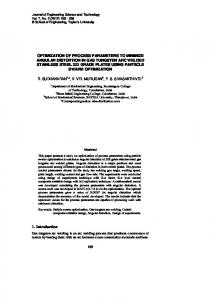
Top view Initial position
Goal position
Task
T=n .kt . I
θ, ω
I. I NTRODUCTION There is a difference between traditional robot control and the way humans control their body: humans use feedforward extensively while traditional robot control is mainly based on feedback. Humans use both feedback and feedforward when sending out motor commands [1]. However, for fast motions, humans cannot rely on feedback at all, due to the large time delays (typically 150 ms for humans [2, 3]). Therefore, they have to rely on feedforward, in which control signals are generated based on the prediction of an (inaccurate) internal model [4]. In feedforward control, humans make use of the fact that most tasks can be executed in multiple or an infinite number of ways, the so-called task redundancy. Experiments on eye movements indicate that humans exploit this task redundancy such that the error in final position due to the influence of uncertainty is minimized [5]. Similar error-minimizing human feedforward motions have been reported for the games of darts and skittles [6, 7, 8, 9]. We will focus on pickand-place tasks of robotic arms, which also possess task redundancy; only the initial and final positions matter and the path in between can be chosen freely. The knowledge from the field of human motion control suggests that some feedforward motions are more sensitive to uncertainty than others. Therefore, we study the sensitivity of feedforward controlled motions to an inaccurate model. ∗ Corresponding author: M.C. Plooij, BioMechanical Engineering, Faculty of Mechanical Engineering, Delft University of Technology, Mekelweg 2, 2628 CD Delft, The Netherlands Email:
[email protected]
I
feedforward controller
t
Fig. 1. A schematic representation of the content of this paper. The one DOF robotic arm has to perform a pick and place task. In this task, the arm has to move from the initial to the goal position. The controller is a feedforward controller, which means that the state (i.e. position θ and velocity ω) is not used to determine the control signal. The control signal is a current I, which is only a function of time. In this paper, we investigate the sensitivity of feedforward motions to parametric model inaccuracies. These model inaccuracies cause the arm to end up in a different position than the goal state. We aim to minimize this error in the final position.
Traditionally, robots mainly use feedback to perform their motions (e.g. PID control). The main reason that robots can rely more on feedback than humans, is their smaller time delays (typically Emax ). • The effect of the viscous friction on the error depends on the feedforward controller (f = 0.7548) and the minimum error is allowable (E = 0.0092 rad < Emax ). However, since the maximum error is also relatively small (E = 0.0374 rad), the factor of improvement is not close to one. • The effect of the torque dependent friction on the error is similar to that of the Coulomb friction: it depends
Minimized
(b) Control signal I (A)
2
0
1.5
0
0.5 1 Time (s)
1.5
(c)
1 0.5 0 −0.5
4
0 (e)
0.5 1 Time (s)
1.5
2
0 +0% +100% -100% Change of parameter value
Angular position (rad)
−2
Final angular position (rad)
Control signal I (A)
(a)
Final angular position (rad)
Angular position (rad)
Maximized 2
0
−2
0
0.5 1 Time (s) (d)
1.5
-20% -10%
1 0.5 0 −0.5
4
1.5
0 (f )
0.5 1 Time (s)
+0% +10% +20% 1.5
2
0 +0% +100% -100% Change of parameter value
1.0004 1
Fig. 5 shows the results for the Coulomb friction optimization in more detail. We clearly see how two different current profiles (Fig. 5a and 5b) lead to different errors (Fig. 5c and 5d), while the nominal motion reaches the goal state. In Fig. 5e, we see that in the motion with minimized error, there is a range of values of the Coulomb friction for which the arm ends up in approximately the same position. This shows that the optimization did not over fit the objective function at the four values of the inaccurate parameter. Similar graphs were obtained for the other optimizations. The optimized current profiles in Fig. 5a and 5b have no clear structure. This is due to the fact that the optimization with 10 controller set points is redundant. This means that there are multiple current profiles that lead to the same (optimal) error value. This redundancy makes it hard to detect a structure in the current profiles. Interestingly, the motion that results from the minimization of the error first moves in the negative direction before moving towards the goal position. We observed such behavior in many of our results. Probably such behavior reduces the effect of the parameter inaccuracy on the final position by canceling out effects in positive and negative direction. IV. H ARDWARE RESULTS
0.9996 -20%
-10%
+0%
+10% +20%
Fig. 5. The results from the optimization with an inaccurate Coulomb friction coefficient. The plots on the left show the results of the minimization of the error, the plots on the right show the results of the maximization of the error. The plots show the optimized current profiles (a and b), five different trajectories as function of time due to five different values for the Coulomb friction coefficient (c and d) and the error in final position as function of change of the parameter value of the Coulomb friction (e and f). The graph also shows enlargements of the end of the position profile of the minimization (c) and the error in position around the nominal value of the Coulomb friction (e). The latter also shows five circles, which represent the final positions of the arm with the nominal value of the Coulomb friction and the four deviating values.
•
•
highly on the feedforward controller (f = 0.9967). There are feedforward controllers for which a change in the torque dependent friction results in an error that is significantly smaller than the maximum allowable error (E = 0.0013 rad < Emax ). However, there are also feedforward controllers for which the error is larger than the errors of all other parameter inaccuracies. Therefore, the factor of improvement is close to one. The effect of the inertia on the error only slightly depends on the feedforward controller (f = 0.1667). Also, the minimal error is significantly larger than the maximum allowable error (E = 0.1775 rad > Emax ). The effect of the motor constant on the error can be reduced by the choice of the feedforward controller (f = 0.4898). However, the minimum error is too large (E = 0.1385 rad > Emax ).
In general, we conclude that inaccuracies in the friction model can be compensated for by the choice of the feedforward controller. Inaccuracies in the inertia and motor constant cannot be compensated for.
In this section, we show the results of the hardware experiments. First, we will explain the test set up and second, we will show the test results. A. The robotic arm Fig. 2b shows a picture of the one DOF robotic arm [18]. The DOF is created by an 18x1.5mm stainless steel tube, connected with a joint. A weight of 1 kg is connected to the end of the tube, which represents the weight of a gripper plus a product. The motor is placed on a housing and AT3gen III 16mm timing belts are used to transfer torques within the housing. The joint is actuated by a Maxon 60W RE30 motor with a gearbox ratio of 18:1. The timing belts provide an additional transfer ratio of 3:1. The model parameters as shown in Table I are based on a system identification of this robotic arm. We tested the results of the optimizations of two parameters: the Coulomb friction and the inertia, because these two parameter inaccuracies give qualitatively different results in simulation (see Fig. 4 and Table II) To change the Coulomb friction, we designed a mechanism that adds Coulomb friction by clamping a nylon sleeve bearing on the motor axis. The Coulomb friction can be increased by tightening the screw of the clamping mechanism. Before each experiment, we ran a system identification to determine the amount of Coulomb friction we added. To change the inertia, we added extra weights at the end point of the arm. Table III shows the values of the parameter changes. B. Results On the robotic arm we did not perform an optimization of the torque profile. Instead, we tested a grid of possible feedforward controllers. Per parameter value for the Coulomb
TABLE III T HE VALUES OF THE CHANGED PARAMETERS IN THE HARDWARE EXPERIMENTS . Parameter µc Jjoint
Nominal value 0.19 0.17
Values in experiments 0.19, 0.22, 0.25 0.17, 0.19, 0.21
Units Nm kgm2
(a) Minimal E on robot Maximal E on robot Minimized E in sim Maximized E in sim
Current (A)
2 1 0 −1 −2 0
0.5
1
1.5
Time(s)
(b) Position (rad)
1.5 1
0% +12% +26% Minimal E Maximal E
0.5 0
−0.5
0
0.5
Time(s)
1
1.5
Fig. 6. A typical example of the data obtained from hardware experiments. This figure shows the minimized and maximized motions for a changing Coulomb friction. a) The feedforward current as function of the time. The solid lines correspond to the motions with minimized and maximized error in hardware experiments. The dashed lines are optimized current profiles in simulation. This graph shows that the current profiles optimized in simulation are the same as the current profiles with minimal and maximal error in hardware experiments. b) The position of the arm as function of the time. We clearly see that the spread in the final position of the minimized motion is smaller than that of the maximized motion. For the minimized motion, it is hard to distinguish the three lines, for the maximized motion the spread is clearly visible. Pc Jjoint
0
0.04
0.08
0.12
Error (rad)
Fig. 7. This figure shows the results of hardware experiments. In these experiments, we tested a grid of 32 possible feedforward controllers. Every star represents the error value as a result of one current profile while varying the Coulomb friction µc or the inertia Jjoint . We see that the results in this figure are comparable to the results from simulation.
friction and inertia, we repeated the experiment with 32 different current profiles. Each current profile had three controller set points of which the first one was determined by a grid of 32 set points. The other two set points were determined by the constraints on the final position and final velocity in simulation. There are two reasons why we use three set points in the hardware experiments instead of the ten we used in simulation. First of all, using three set points makes it feasible to test a grid of controllers since the grid is one dimensional. Second, due to the switches in the controller, the influence of the unmodeled backlash increases and using only three controller set points minimizes the influence of this backlash. In Section V we will show that
TABLE IV T HE RESULTS OF THE ONE DOF HARDWARE EXPERIMENTS . Parameter µc JJoint
Eminimized (rad) 0.001 0.040
Emaximized (rad) 0.092 0.073
f 0.982 0.457
by limiting ourselves to three controller set points instead of ten, the factors of improvement will change but will still show the same trend (e.g. 10% change for an inaccurate Coulomb friction). Fig. 6 shows the current and the position as function of the time of a typical experimental run. It also shows that the current profiles with minimal and maximal error in hardware experiments correspond to the current profiles with minimized and maximized error in simulation. For systems with more DOFs, the current profiles from optimization should be used instead of a less feasible grid search. Per value of the first setpoint, we calculated the RMS of the error in the final position with respect to the final position of the motion with the nominal parameter value. Fig. 7 and Table IV show the error values that were obtained from the hardware experiments. From these results, we see that: • The results of the hardware experiments with an inaccurate Coulomb friction are comparable to the results from simulation. The maximum error in simulation and hardware experiments are respectively 0.1164 rad and 0.092 rad and in both cases, the minimum error is approximately zero. Furthermore, the error due to an inaccurate Coulomb friction has a larger spread than the error due to an inaccurate inertia. • The results of the hardware experiments with an inaccurate inertia differs from the results from simulation. The main difference is that the errors are smaller in the hardware experiments. Since the difference between the minimum and maximum error is the same in simulation and the hardware experiments (respectively 0.0356 rad and 0.033 rad), the factor of improvement is larger in the hardware experiments. We conclude that although there clearly are differences between the simulations and the hardware results, in general the hardware experiments confirm the conclusions from the simulation study: the errors due to inaccuracies in the Coulomb friction can be reduced to approximately zero, while the errors due to inaccuracies in the inertia are always larger than the maximum allowable error Emax . V. D ISCUSSION In this study we researched motions of a one DOF robotic arm, controlled by feedforward control. The task consisted of fixed initial and goal positions and a fixed time per stroke. The motion in between was only constrained by the maximum current. We showed that the choice of the motions in between the initial and goal positions is important for the error in the final position due to parametric model inaccuracies. For the one DOF system, the error in the final position can even be reduced to approximately zero when
B. Choice of optimization parameters In Section II, we introduced the task parameters time and distance per stroke and their values. We also introduced values for the maximum current and the number of set points of the feedforward controller. Since these values are arbitrary, we analyzed how the results in this paper depend on the chosen parameter values. We varied those parameters and ran the optimizations again to evaluate their influence. Fig. 8 shows the result of this analysis. From these results, we conclude that: • The number of controller set points does not influence the optimizations, as long as there are enough set points. For all optimizations, six set points appears to suffice. • The effects of the choice of the distance per stroke, time per stroke and maximum current are related. A too low maximum current, too large distance per stroke or too short time per stroke lead to a decreased performance. This is intuitive since the maximum current should be high enough to move the distance per stroke within the time per stroke. • The factors of improvement increase when we increase the time per stroke or the maximum current. This suggests that the system is approximately controllable [14, 19, 20]. The approximate controllability of robotic arms is an interesting topic for future research. In general, we conclude that the specific results depend on the choice for the distance per stroke, time per stroke and maximum current. However, the qualitative results are the same for reasonable values for those parameters.
factor of improvement f
Pc
1
Pv Pt
0.5
Jjoint kt 0 0 (b)
factor of improvement f
The results of this study are important to consider when implementing feedforward control, even in combination with feedback control. The correct use of feedforward control improves the performance of the system and this study shows that the performance can even be improved in such a way that certain model parameters do not have to be known accurately. An interesting result was that most optimized motions do not move from the initial to the goal position directly, but first move away from the goal position. This study also has implications on the field of human motion control. Recent studies in the field of human motion control focused on the uncertainty (i.e. noise) in the control signals [5]. It would be interesting to research the accuracy of the internal models of humans and the influence of this accuracy on the motions humans choose. Another interesting topic for future research would be the influence of noise on the performance of feedforward control in robotic systems.
factor of improvement f
A. Implications
(a)
5 10 15 Number of controller setpoints N
20 Pc
1
Pv Pt
0.5
Jjoint kt 0
0.5 (c)
1 1.5 Distance per stroke (rad)
2 Pc
1
Pv Pt
0.5
Jjoint kt 0
5
1 1.5 Time per stroke (s)
(d) factor of improvement f
the Coulomb friction, viscous friction or torque dependent friction are not accurately known.
2 Pc
1
Pv Pt
0.5
Jjoint kt 0 1
1.5
2 2.5 Maximum current (A)
3
3.5
Fig. 8. This figure shows four analyses of the influence of the choice of four parameters on the results in this paper. The four graphs show the factors of improvements we obtain through optimization for various number of controller set points (a), distance per stroke (b), time per stroke (c) and maximum current (d).
Pc Pv Pt Jjoint kt
0
0.1
0.2 Error (rad)
0.3
0.4
Fig. 9. This figure shows bars from the minimal to the maximal errors of the one DOF model using voltage feedforward control instead of current feedforward control.
C. Voltage control In this paper we considered torque control, which we implemented as current control. However, the lowest level of control in the electronics is voltage control (i.e. controlling the pulse width modulation). Fig. 9 shows the results of the
one DOF optimization using voltage feedforward control. By comparing Fig. 4 and Fig. 9, we conclude that the conclusions in this paper would have been the same had we used voltage control.
D. Future work There are four topics that need to be addressed in future work in order to make feedforward control fully applicable. Firstly, a more analytical approach, could lead to a deeper understanding of paths that are insensitive to model inaccuracies. Secondly, in practice it is likely to have multiple parameter inaccuracies. Therefore, future research should include optimization of feedforward controllers for multiple parameter inaccuracies simultaneously. Thirdly, more complex systems (e.g. system with more DOFs) have to be researched. Finally, in order to prevent the error from accumulating after multiple motions, the stability of feedfoward motions needs to be addressed. A promising approach could be to analyze cyclic pick-and-place tasks with the use of limit cycle theory. VI. C ONCLUSIONS In this paper, we showed that by optimizing the feedforward controller for a one DOF robotic arm, we can reduce the sensitivity for an inaccuracy in all model parameters. For the three friction parameters (Coulomb friction, viscous friction and torque dependent friction), the errors in the final positions can even be reduced to approximately zero. For the inertia and the motor constant, the errors in the final positions can be reduced, but not to zero. ACKNOWLEDGEMENT This work is part of the research programme STW, which is (partly) financed by the Netherlands Organisation for Scientific Research (NWO). R EFERENCES [1] M. Desmurget and S. Grafton, “Forward modeling allows feedback control for fast reaching movements,” Trends in cognitive sciences, vol. 4, no. 11, pp. 423– 431, 2000. [2] S. Thorpe, D. Fize, and C. Marlot, “Speed of processing in the human visual system,” Nature, vol. 381, no. 6582, pp. 520–522, 1996. [3] P. Cordo, L. Carlton, L. Bevan, M. Carlton, and G. K. Kerr, “Proprioceptive coordination of movement sequences: role of velocity and position information,” Journal of Neurophysiology, vol. 71, no. 5, pp. 1848– 1861, 1994. [4] M. Kawato, “Internal models for motor control and trajectory planning,” Current Opinion in Neurobiology, vol. 9, no. 6, pp. 718 – 727, 1999. [5] C. M. Harris and D. M. Wolpert, “Signal-dependent noise determines motor planning,” Nature, vol. 394, no. 6695, pp. 780–784, 1998. [6] J. Smeets, M. Frens, and E. Brenner, “Throwing darts: timing is not the limiting factor,” Experimental Brain Research, vol. 144, pp. 268–274, 2002, 10.1007/s00221-002-1072-2. [7] H. M¨uller and E. Loosch, “Functional variability and an equifinal path of movement during targeted throwing,” Journal of Human Movement Studies, vol. 36, pp. 103– 126, 1999.
[8] H. M¨uller and D. Sternad, “Decomposition of variability in the execution of goal-oriented tasks: Three components of skill improvement.” Journal of Experimental Psychology: Human Perception and Performance, vol. 30, no. 1, pp. 212–233, 2004. [9] R. G. Cohen and D. Sternad, “State space analysis of timing: exploiting task redundancy to reduce sensitivity to timing,” Journal of Neurophysiology, vol. 107, no. 2, pp. 618–627, 2012. [10] S. Schaal and C. Atkeson, “Open loop stable control strategies for robot juggling,” in Robotics and Automation, 1993. Proceedings., 1993 IEEE International Conference on, may 1993, pp. 913 –918 vol.3. [11] A. Seyfarth, H. Geyer, and H. Herr, “Swing-leg retraction: a simple control model for stable running,” Journal of Experimental Biology, vol. 206, no. 15, pp. 2547– 2555, 2003. [12] K. Mombaur, R. Longman, H. Bock, and J. Schl¨oder, “Open-loop stable running,” Robotica, vol. 23, no. 1, pp. 21–33, 2005. [13] K. D. Mombaur, H. G. Bock, J. P. Schl¨oder, and R. W. Longman, “Open-loop stable solutions of periodic optimal control problems in robotics,” ZAMM-Journal of Applied Mathematics and Mechanics/Zeitschrift f¨ur Angewandte Mathematik und Mechanik, vol. 85, no. 7, pp. 499–515, 2005. [14] A. Becker and T. Bretl, “Approximate steering of a unicycle under bounded model perturbation using ensemble control,” IEEE Transactions on Robotics, vol. 28, no. 3, pp. 580–591, 2012. [15] P. E. Dupont, “The effect of coulomb friction on the existence and uniqueness of the forward dynamics problem,” in Robotics and Automation, 1992. Proceedings., 1992 IEEE International Conference on. IEEE, 1992, pp. 1442–1447. [16] B. Barmish and C. Lagoa, “The uniform distribution: A rigorous justification for its use in robustness analysis,” Mathematics of Control, Signals, and Systems (MCSS), vol. 10, no. 3, pp. 203–222, 1997. [17] E. Bai, R. Tempo, and M. Fu, “Worst-case properties of the uniform distribution and randomized algorithms for robustness analysis,” Mathematics of Control, Signals, and Systems (MCSS), vol. 11, no. 3, pp. 183–196, 1998. [18] M. Plooij and M. Wisse, “A novel spring mechanism to reduce energy consumption of robotic arms,” in Proceedings of the 2012 International Conference on Intelligent Robots and Systems, 10 2012, pp. 2901– 2908. [19] K. Beauchard, J. Coron, and P. Rouchon, “Controllability issues for continuous-spectrum systems and ensemble controllability of bloch equations,” Communications in Mathematical Physics, vol. 296, no. 2, pp. 525–557, 2010. [20] J. Li, “Control of inhomogeneous ensembles,” Ph.D. dissertation, Harvard University Cambridge, Massachusetts, 2006.