OPTIMIZATION OF SECOND HARMONIC INPUT IMPEDANCE FOR HIGH CONVERSION GAIN FREQUENCY DOUBLER YOUNKYU CHUNG Department of Electrical Engineering, University of California, Los Angeles 405 Hilgard Ave., Los Angeles, CA, 90095, USA E-mail:
[email protected] DAL AHN Division of Information Technology Engineering, Soonchunhyang University, Choongnam, Korea E-mail:
[email protected] TATSUO ITOH Department of Electrical Engineering, University of California, Los Angeles 405 Hilgard Ave., Los Angeles, CA, 90095, USA E-mail:
[email protected] Design of a high conversion gain frequency doubler has been presented in this paper by optimizing the input impedance at the second harmonic frequency. A LC tank resonator, as a second harmonic impedance optimizer at input side, properly adjusts the harmonic impedance without affecting matching performance at fundamental frequency. In practice, a stepped impedance resonator was utilized for realizing the designed input impedances at both fundamental and the second harmonic frequency. Based on this design technique, a 5 to 10 GHz single-ended GaAs FET frequency doubler was designed, fabricated, and tested. For the frequency doubler configuration, conversion gain of 7.34 dB and saturated output power of 8.17 dBm was achieved when the FET was biased in pinch-off region, rich second harmonic.
1.
Introduction
The inherent upper limit of operating frequency in designing amplifiers and oscillators in microwave and millimeter-wave communication and radar systems leads frequency multipliers to be important and popular circuits as signal sources. This is due to lower phase noise and better frequency stability than in a single high frequency local oscillator [1]. The field effect transistors (FETs), high electron mobility transistors (HEMTs) or varactor diodes have been often employed in the design of frequency multipliers [1-4]. Despite excellent performance of passive multipliers in terms of spectral purity, they suffer from high conversion loss and small output power. On the other hand, active multipliers consisting of FETs or HEMTs provide frequency conversion gain rather than loss and more output power. However, since the frequency conversion occurs by forcing the FETs or diodes to operate in the strong nonlinear region and to generate harmonic signals, it is difficult to obtain relatively high output power at desired harmonic frequencies. The conversion gain performance of the active frequency
multiplier has been enhanced by employing the harmonic reflectors [2-5]. A quarter-wave length microstrip line designed at the second harmonic frequency is commonly used as the frequency reflector at input matching side [2-3]. Moreover, the performance of the multiplier has been studied by taking into account proper impedance termination of high order harmonics at both output and input sides [4-5]. Since the device nonlinearities cause many frequency components to mix together so that the desired signal may be enhanced or degraded depending upon the phase quantity. In this paper, the effect of second harmonic input impedance on the conversion gain of a singleended GaAs FET frequency doubler has been studied. By means of a stepped impedance resonator, both fundamental frequency and second harmonic impedances were optimized to achieve the maximum conversion gain. Simulation and experimental measurements on a 5 to 10 GHz frequency doubler with the stepped impedance resonator using a commercial FET, NEC 76038, are provided in section 2 and 3, respectively.
2.
Design and Analysis
A basic single-ended frequency doubler configuration as shown in Fig.1 has been considered in this paper. The design of output network is done to pass the desired second harmonic while suppressing the fundamental frequency. On the other hand, in the input side, the fundamental frequency signal is applied to the nonlinear device through the matching network. In addition, an inductor and capacitor (LC) tank resonator is inserted to properly adjust the second harmonic input impedance.
Fig. 1 Architecture of single-ended frequency doubler with a second harmonic impedance optimizer
The LC resonator not only reflects the second harmonic signal but also can be adjusted to maximize the desired output power by taking into account its phase. Since the operating frequency of the resonator is defined by the multiplication of Lres and Cres values as shown in equation (1), the second harmonic impedance is easily optimized by changing these two values while keeping the multiplication value constant to avoid any effect on the fundamental frequency impedance.
ϖ0 =
1 Lres ⋅ Cres
(1)
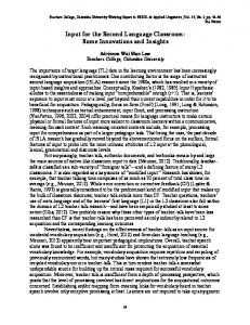
This design principle was tested in the design of a 5 to 10 GHz frequency doubler. Fig. 2 shows the ADS simulation schematic of the doubler circuit. For this simulation the ADS harmonic balance simulator and a packaged 280 µm-wide NEC 76038 GaAs FET nonlinear model was utilized. First, an optimum output impedance at the 10 GHz second harmonic frequency for maximum output power from the GaAs FET was extracted using load-pull simulation. The FET was biased to class-B to easily generate even harmonics. The 5 to 10 GHz single-ended frequency doubler without taking into account the adjustment of the second harmonic impedance was designed first based upon the output impedance. Then the resonator was placed in the input matching side and tuned. A 5 GHz quarter-wave length line in the output network operates as a simple fundamental frequency reflector. Note that input power was set to 1 dBm in this harmonic balance simulation and the capacitor values of the C1, C2, and C3 were 1.8 pF, 1.3 pF, and 0.3 pF, respectively. In Fig. 3, the output powers at the 5 GHz fundamental and 10 GHz desired harmonic frequencies are shown as the Lres varies from 0.25 nH to 10 nH, which corresponds the Cres from 4 pF to 0.1 pF, respectively. It is clearly seen that 10 GHz output power is dependent on the inductance and capacitance due to adjustment of harmonic impedance. In this simulation, about 2 nH Lres and 0.5 pF Cres provides maximum conversion gain. However, the 5 GHz signal output power remains constant because of the resonator designed at 5 GHz, which implies that the input matching performance is not affect by the resonator.
Fig. 2 ADS simulation schematic of single-ended frequency doubler
0
10
8
5
Pout [dBm @10 GHz]
12
conversion gain occurs at 9.9 GHz instead of the designed 10 GHz due to imperfectness of circuit fabrication. The maximum conversion gain and saturated output power reach up to 8.3 dB and 9 dBm , respectively at 9.9 GHz.
6 0 4 -5 2 -10 Conversion Gain Pout
10 -10 8
6 -20 Pout (2fo) Pout (fo)
4
2
Output power [dBm]
Output power [dBm]
Conversion Gain [dB]
In practice, instead of the LC resonator a stepped impedance resonator was utilized to realize impedances at fundamental and the second harmonic frequencies of the LC resonator [6]. The electrical length of each segment of the stepped impedance resonator as well as the characteristic impedances of the segments was calculated based on the equations [6]. Therefore, two impedances at the fundamental and second harmonic frequencies realized by the stepped impedance resonator were same as those by the LC tank resonator.
-15 -20
0 -15
-10
-5
0
5
Pin [dBm @ 5 GHz]
Fig. 4. Measured output power (Pout) and conversion gain with respect to input power for the frequency doubler.
-30 0
1
2
3
4
5
6
7
8
9
10
3. Single-Ended FET Frequency Doubler The designed GaAs FET single-ended frequency doubler was fabricated on Duroid substrate with εr=2.33 and thickness of 31 mils. For testing large-signal performance of the frequency doublers, the bias voltages were set to same as simulation, VDS of 3 V and VGS of -0.8 V, in class-B operation. The measured output power at 10 GHz and the conversion gain with respect to 5 GHz input power is shown in Fig. 4. An output power of 7.5 dBm and a conversion gain of 6.67 dB at an input power of 1 dBm were obtained. A maximum conversion gain of 7.34 dB at an input power level of -4 dBm and saturated Pout of 8.17 dBm were obtained. In Fig. 5, the measured conversion gain and saturated output power characteristic of the frequency doubler as a function of frequency over a range from 9.4 to 10.2 GHz is shown. The measured output frequencies are the second harmonics of the corresponding to the input frequencies, respectively. The maximum
12
10
10
8
8
6
6
4
4
2 Pout Conversion Gain
2
0
0
Conversion Gain [dB]
Fig. 3 Simulated output power at fundamental and second harmonic frequencies as a function of Lres
Saturated Pout [dBm]
Lres [nH]
-2
-2 9.4
9.5
9.6
9.7
9.8
9.9
10
10.1
-4 10.2
Frequency [GHz]
Fig. 5. Measured saturated output power (Pout) and conversion gain as a function of frequency for the frequency doubler.
4.
Conclusion
A high conversion gain single-ended frequency doubler scheme has been demonstrated. The second harmonic input impedance has been taken into account in this design. By means of stepped impedance resonator at the input matching side, the impedance was optimized without affecting input matching at fundamental frequency, thereby maximizing the desired second harmonic output power. The optimised 5 to 10 GHz frequency doubler
shows a 7.34 dB conversion gain and 10 GHz saturated output power of 8.17 dBm. Up to 8.3 dB maximum conversion gain and 9 dBm saturated output power was measured from the doubler over the frequency range from 9.4 to 10.2 GHz.
Acknowledgements The authors would like to thank Dr. Jong-Sik Lim at Seoul National University, Seoul, Korea for helpful discussions.
References [1] M. Funabashi, T. Inoue, K. Ohata, K. Maruhashi, K. Hosoya, M. Kuzuhara, K. Kanakawa, and Y. Kobayashi, “A 60 GHz MMIC stabilized frequency source composed of a 30 GHz DRO and a doubler,” IEEE MTT-S Int. Microwave Symp. Dig., pp. 71-74, 1995. [2] C. Rauscher, “High-frequency doubler operation of GaAs field-effect transistors,” IEEE Trans. Microwave Theory Tech, vol. 31, no. 6, pp. 462-473, 1983. [3] Y. Iyama, A. Iida, T. Takagi, and S, Urasaki, “Second-harmonic reflector type high-gain FET frequency doubler operating in K-band,” IEEE MTT-S Int. Microwave Symp. Dig., pp. 1291-1294, 1989. [4] D. G. Thomas, Jr. and G. R. Branner, “Single-ended HEMT multiplier design using reflector networks,” IEEE Trans. Microwave Theory Tech, vol. 49, no. 5, pp. 990-993, 2001. [5] D. G. Thomas, Jr. and G. R. Branner, “Optimization of active microwave frequency multiplier performance utilizing harmonic terminating impedance,” IEEE Trans. Microwave Theory Tech, vol. 44, no.12, pp. 2617-2624, 1996. [6] M. Makimoto and S. Yamashita, “Bandpass filters using parallel coupled stripline stepped impedance resonators,” IEEE Trans. Microwave Theory Tech, vol. 28, no.12, pp. 1413-1417, 1980.