290
J. W. HORNG, C.-H. HSU, C.-Y. TSENG, HIGH INPUT IMPEDANCE VOLTAGE-MODE UNIVERSAL BIQUADRATIC FILTERS …
High Input Impedance Voltage-Mode Universal Biquadratic Filters with Three Inputs Using Three CCs and Grounding Capacitors Jiun-Wei HORNG, Chih-Hou HSU, Ching-Yao TSENG Dept. of Electronic Engineering, Chung Yuan Christian University, Chung-Li, 32023, Taiwan
[email protected] Abstract. Two current conveyors (CCs) based high input impedance voltage-mode universal biquadratic filters each with three input terminals and one output terminal are presented. The first circuit is composed of three differential voltage current conveyors (DVCCs), two grounded capacitors and four resistors. The second circuit is composed of two DVCCs, one differential difference current conveyor (DDCC), two grounded capacitors and four grounded resistors. The proposed circuits can realize all the standard filter functions, namely, lowpass, bandpass, highpass, notch and allpass filters by the selections of different input voltage terminals. The proposed circuits offer the features of high input impedance, using only grounded capacitors and low active and passive sensitivities. Moreover, the x ports of the DVCCs (or DDCC) in the proposed circuits are connected directly to resistors. This design offers the feature of a direct incorporation of the parasitic resistance at the x terminal of the DVCC (DDCC), Rx, as a part of the main resistance.
Keywords Current conveyor, biquadratic filter, active circuit.
1. Introduction The differential difference current conveyors (DDCC) [1] or differential voltage current conveyors (DVCC) [2] have received considerable attention due to they enjoy the advantages of second-generation current conveyor (CCII) and differential difference amplifier (DDA) such as larger signal bandwidth, greater linearity, wider dynamic range, simple circuitry, low power-consumption, and arithmetic operation capability. Moreover, it has two or three high input impedance voltage terminals (y terminals) that make easy to synthesize circuits. The circuit design uses only grounded capacitors is attractive, because grounded capacitor can be implemented on a smaller area than the floating counterpart and it can absorb equivalent shunt capacitive parasitic [3], [4]. High
input impedance voltage-mode active filters are of great interest because several cells of this kind can be directly connected in cascade to implement higher order filters [5], [6]. Because the DVCC (or DDCC) has a non-negligible resistance on port x (Rx) [7], when the x port of DVCC is loaded by a capacitor, it leads to improper transfer functions. Due to the effect of this parasitic resistance Rx at the x port of DVCC, the filters with x port loaded by a capacitor do not exhibit good performance at high frequency. Several voltage-mode universal biquads each with three input terminals were presented in [8]-[19]. Five kinds of standard filter functions can be derived by the selections of different input voltage terminals in these circuits. However, these circuits suffer from one or more of the following drawbacks: use floating capacitors [8], [10], [11], [14]-[16], [18], [19], need more active components for the unity gain inverting inputs in some filter realizations [8], [10], [15], [18], [19], low input impedance [9], [10], [13]-[16], [18], [19], the resonance angular frequency and quality factor cannot be orthogonally controllable [8]-[12], [14][16], [18], [19], the x ports of the current conveyors are not connected directly to resistors [8], [10], [11], [15], use too many active and passive components [17]. In 2000, Minaei and Yuce [20] presented a DVCC based voltage-mode universal biquad with three input terminals. This circuit uses two grounded capacitors, three grounded resistors and three DVCCs. In this paper, two new high input impedance voltagemode universal biquadratic filters each with three input terminals using three DVCCs (or DDCC) is presented. Each of the proposed circuits uses four resistors and two grounded capacitors. The proposed circuits have the following features: (i) five standard filter functions, that is, highpass, bandpass, lowpass, notch, and allpass filters can
RADIOENGINEERING, VOL. 21, NO. 1, APRIL 2012
291
be obtained from the same circuit configuration, (ii) high input impedance, (iii) low active and passive sensitivities, and (iv) the x ports of the DVCCs (or DDCC) are connected directly to resistors.
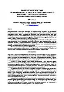
If Vin2 = Vin3 = 0 (grounded), then Vin1 = input voltage signal, a lowpass filter can be obtained with Vout/Vin1. If Vin1 = Vin3 = 0 (grounded), then Vin2 = input voltage signal, a bandpass filter can be obtained with Vout/Vin2. If Vin1 = Vin2 = 0 (grounded), then Vin3 = input voltage signal, a highpass filter can be obtained with Vout/Vin3. If Vin2 = 0 (grounded), then Vin1 = Vin3 = Vin = input voltage signal, a notch filter can be obtained with Vout/Vin. If Vin1 = Vin2 = Vin3 = Vin = input voltage signal and let R2 = R3 = R4, an allpass filter can be obtained with Vout/Vin. The resonance angular frequency ωo and the quality factor Q are given by
Fig. 1. The first proposed voltage-mode universal biquadratic filter.
and
2. The Proposed Biquadratic Filters Using standard notation, the port relations of a DVCC can be described by the following matrix equation [2]:
0 i y1 0 0 i 0 0 0 y2 v x 1 1 0 i z 0 0 1
0 v y1 0 v y 2 0 i x 0 v z
(1)
ωo
G1G 2 G3 C1C 2 G 4
(4)
Q
C2G1G2 . C1G3G4
(5)
Thus, all the standard filter functions (highpass, bandpass, lowpass, notch, and allpass) can be obtained from the proposed circuit in Fig. 1. Due to the three input signals, Vin1, Vin2 and Vin3 are connected directly to the high input impedance input nodes of the three DVCCs (the y port of the DVCC), respectively, the circuit enjoys the feature of high input impedance. The proposed circuit uses only two grounded capacitors, which are attractive for integrated circuit implementation.
where the plus and minus signs indicate whether the DVCC is configured as a non-inverting or inverting circuit, termed DVCC+ or DVCC-. Using standard notation, the port relations of a DDCC can be described by the following matrix equation [1]:
i y1 0 0 i 0 0 y2 i y 3 0 0 v x 1 1 iz 0 0
0 v y1 0 v y 2 0 v y 3 1 0 0 i x 0 1 0 v z 0 0 0
0 0 0
(2)
where the plus and minus signs indicate whether the DDCC is configured as a non-inverting or inverting circuit, termed DDCC+ or DDCC-. Considering the first proposed circuit in Fig. 1, the output voltage can be expressed as
Vout
s 2C1C 2G3Vin 3 sC1G2G3Vin 2 G1G2G3Vin1 . s 2C1C 2G4 sC1G3G4 G1G2G3
From (3), we can see that:
Fig. 2. The second proposed voltage-mode universal biquadratic filter.
Considering the second proposed circuit in Fig. 2, the output voltage can be expressed as
( s 2C1C2G3 G1G2G3 )Vin 3
(3)
Vout
sC1G2G3Vin 2 G1G2G3Vin1 . s C1C2G4 sC1G2G3 G1G2G4 2
(6)
292
J. W. HORNG, C.-H. HSU, C.-Y. TSENG, HIGH INPUT IMPEDANCE VOLTAGE-MODE UNIVERSAL BIQUADRATIC FILTERS …
From (6), we can see that: If Vin2 = Vin3 = 0 (grounded), then Vin1 = input voltage signal, a lowpass filter can be obtained with Vout/Vin1. If Vin1 = Vin3 = 0 (grounded), then Vin2 = input voltage signal, a bandpass filter can be obtained with Vout/Vin2. If Vin1 = Vin2 = 0 (grounded), then Vin3 = input voltage signal, a notch filter can be obtained with Vout/Vin3. If Vin2 = 0 (grounded), then Vin1 = Vin3 = Vin = input voltage signal, a highpass filter can be obtained with Vout/Vin. If Vin1 = 0 (grounded), then Vin2 = Vin3 = Vin = input voltage signal and let R3 = R4, an allpass filter can be obtained with Vout/Vin. The resonance angular frequency ωo and the quality factor Q are given by
ωo and
Q
G4 G3
G1G 2 C 1C 2
(7)
C2G1 . C1G2
(8)
Thus, all the standard filter functions (highpass, bandpass, lowpass, notch, and allpass) can be obtained from the proposed circuit in Fig. 2. Due to the three input signals, Vin1, Vin2 and Vin3 are connected directly to the high input impedance input nodes of the DVCCs or DDCC (the y port of the DVCCs or DDCC), respectively, the circuit enjoys the feature of high input impedance. This circuit uses only grounded capacitors and resistors, which are attractive for integrated circuit implementation. From (7), (8), the resonance angular frequency can be controlled by R1 or R2. The quality factor can be independently controlled by R3 or R4. From Fig. 1 and Fig. 2, the three resistors R1, R2, R3 are connected to the three x terminals of the three DVCCs (or DDCC), respectively. This design offers the feature of a direct incorporation of the parasitic resistance at the x terminal of the DVCC (DDCC), Rx, as a part of the main resistance. Since the output impedances of the proposed circuits are not small, voltage followers are needed while cascaded the proposed circuits to the next stages.
3. Sensitivities Analysis Taking the non-idealities of the DVCC or DDCC into account, the relationship of the terminal voltages and currents of DVCC can be rewritten as
0 0 i y1 0 i 0 0 0 y2 v x k1 ( s) k 2 (s) 0 0 k ( s) iz 0
0 v y1 0 v y 2 0 i x 0 v z
The relationship of the terminal voltages and currents of DDCC can be rewritten as
0 0 0 i y1 0 i 0 0 0 0 y2 i y 3 0 0 0 0 v ( s ) ( s ) ( s ) 0 k2 k3 x k1 i z 0 k (s) 0 0
0 v y1 0 v y 2 (10) 0 v y 3 0 i x 0 v z
where αk1(s), αk2(s) and αk3(s) represent the frequency transfer functions of the internal voltage followers and βk(s) represent the frequency transfer function of the internal current follower of the k-th DDCC (or DVCC). They can be approximated by first order lowpass functions, which can be considered to have a unity value for frequencies much lower than their corner frequencies [21]. If the circuit is working at frequencies much lower than the corner frequencies of αk1(s), αk2(s), αk3(s) and βk(s), then αk1(s) = αk1 = 1 - k1 and k1 (|k1|