Optimization of Taxiway Routing and Runway Scheduling Gillian Clare∗ and Arthur Richards† University of Bristol, Bristol, UK
Abstract This paper describes a Mixed Integer Linear Programming (MILP) optimization method for the coupled problems of airport taxiway routing and runway scheduling. The Receding Horizon (RH) formulation and use of iteration in the avoidance constraints allows the scalability of the baseline algorithm presented to be illustrated, with examples based on Heathrow airport containing up to 240 aircraft. The results show that average taxi times can be reduced by 55% when compared to a First Come First Serve (FCFS) approach. The main advantage is seen with the departure aircraft flow. Comparative testing demonstrates that iteration reduces the computational demand of the required separation constraints whilst introducing no loss in performance. RH formulation enables near real-time operation as the computation is spread between horizons preventing unnecessarily detailed plans being calculated for the distant future. The conversion to RH does however result in an approximation to the globally optimal solution, although this is shown to be relatively small.
Manuscript received ∗
Ph.D. Candidate, Department of Aerospace Engineering, University of Bristol, Queens Building, University Walk, Bristol BS8 1TR;
[email protected], Student Member AIAA. †
Lecturer, Department of Aerospace Engineering, University of Bristol, Queens Building, University Walk, Bristol BS8 1TR;
[email protected], Member AIAA.
1
Key words: Optimization, Mixed-integer Programming, Taxi Routing, Runway
Nomenclature a, b, c
Identify Aircraft
aL (n)
The last aircraft to visit node n prior to current horizon
ax
Auxiliary aircraft
A
Set of all active aircraft
Aarr
Set of all arriving aircraft
Adep
Set of all departing aircraft
Ax
Set of all auxiliary aircraft
C(n, m)
Absolute binary connectivity matrix
Ca (n, m)
Binary connectivity matrix for aircraft a
dt (a, b, n)
Temporal separation required between aircraft a and b at node n
DSE
Binary Variable
DOT
Binary Variable
DHO
Binary Variable
F CF S
First Come First Serve
gSE
Binary Ordering Switch for Separation conflict
gCO
Binary Ordering Switch for Cross-Over conflict
gRO
Binary Ordering Switch for Runway conflict
k, j
Identify planning periods
G
Set of all gate nodes
L(n, m)
Topology distances 2
Ltaxi (a)
Distance taxied previous to current problem
M
Large number
n, m
Identify nodes (intersections) on the taxiways
n0 (a)
Origin node of aircraft a
nD (a)
Destination node of aircraft a
nF (a)
Final node in aircraft a’s detailed plan
nRa
Arrival runway node
nRd
Departure runway node
nv (a)
Virtual node introduced by aircraft a
Na
Number of aircraft in the problem
Nn
Number of nodes in the airport graph structure
Nk
Number of planning periods in the problem
N
Set of all nodes in the airport graph structure
CO, COi , COdet
Set of crossover conflicts: all, those enforced in iteration i, those detected
rST (n, m)
Shortest path through the airport graph structure between nodes n and m
R(a, k)
Routing variable recording the node at which aircraft a begins planning period k
RH
Receding Horizon
RO
Set of all possible departure runway conflicts
SE, SEi , SEdet
Set of separation conflicts: all, those enforced in iteration i, those detected
tD (a)
Destination time for aircraft a’s
tstart (a)
Universal time at which aircraft a started taxiing
t0 (a)
Origin time of aircraft a
T (a, k)
Time at which aircraft a passes the node in it’s kth planning period 3
TL (n)
Time at which node n was last visited prior to current horizon
Tt (a)
Time aircraft a taxied prior to current horizon
V (a)
Maximum speed of aircraft a
wi
Weightings in the objective function
X(a, n, m, p)
Binary representation of aircraft movement plans
1
Introduction
Meeting the increasing air traffic demand, which is expected to more than double between 2005 and 2020 [1], within the current air traffic system requires improvements in all areas of Air Traffic Management (ATM). Significant improvements in en-route ATM are shifting the system bottle neck to the limited airport capacity. Congestion on the airport surface is a major constraint to the available capacity of the air transport system. Economically, congestion reduces the turnaround efficiency, while environmentally the increase in both air pollutant and noise emissions impact negatively upon the local region. Furthermore, congestion causes concerns for controller workload [2] and increased risk of runway incursion [3]. The practical difficulties of increasing capacity through airport expansion introduces the desire for enhanced airport ground movement efficiency by intelligent use of the existing resources. Projects such as Eurocontrol’s Advanced-Surface Movement, Guidance and Control Systems (A-SMGCS) [4], and the European Commission’s European airport Movement Management by A-SMGCS (EMMA) [5] have begun the development of new technology and systems of operation to improve upon current practices. Optimization of airport ground operations is an important topic in modern transportation
4
research and several approaches have been investigated. Surface movement research has mainly focussed on subsets of the problem which can be classified as: arrival and departure management, including runway sequencing and scheduling [6–9]; stand allocation [10]; and taxi planning, including route allocation followed by local deconfliction [11], and route scheduling [12]. Ref.13 introduces three separate yet interacting schedulers for the runway, ramp and taxiway system. Ref.14 performs both routing and timing optimization, although using discrete time steps and not including take-off separation on the runway. In contrast this paper considers the problem in continuous time, which prevents conservative rounding, considered to be beneficial [15] and incorporates departure runway scheduling, as this has been identified as the key flow constraint to surface movement [16]. This paper describes an automated tool for airport taxiway routing and runway scheduling which applies non-convex optimization to the surface movement problem. The key features of this work are coupled routing and timing optimization, incorporation of runway scheduling, and the implementation in continuous time. This combines discrete decisions, choosing among predetermined taxiways, with continuous decisions, relating to the timing of the planned movement. The method in this paper adopts Mixed Integer Linear Programming (MILP) optimization, known to be suited to such hybrid problems [17]. MILP has previously been successfully used in Air Traffic Management optimizers for both en-route [18] and ground [11, 12] traffic. This type of formulation can be solved using efficient, commercial software, such as CPLEX [19], generating globally optimal solutions. Airport surface movement optimization is NP-hard [20] due to the dynamic traffic assignment when the coupled non-convex decisions of routing and timing are simultaneously optimized. There are many individual constraints such as push-back times, taxiway layouts, and runway separations all requiring consideration. The runway operations alone are constrained by both wake vortex
5
separations and downstream flight path, or Standard Instrument Departure (SID) separations [21]. This level of complexity results in computationally demanding optimizations. The dynamic nature of the problem, with aircraft entering and leaving, and the possibility of unexpected events, requires plans to be updated regularly. These factors motivate a formulation with reduced computational demand. This was achieved by the RH formulation and use of iteration in the avoidance constraints in the baseline algorithm presented. RH schemes have been used extensively before in trajectory planning [22,23] as the framework is well suited to such problems. The optimization combines detailed near-term planning over a finite period called the planning horizon with coarse far-term approximations beyond this; this plan is then implemented up to a shorter ‘execution’ horizon, before re-planning occurs, with inputs from the state that has been reached during execution. The continuous nature of traffic at airports is well modelled by the continuation of one horizon to the next, as this allows for inclusion of a rolling window [9,12]. Practically this introduced scalability, as the optimizer considers only a ‘window’ of the aircraft from the entire problem in and given horizon, with aircraft able to enter and leave the problem between the optimizations for each horizon. As a result, computation is spread between horizons preventing unnecessarily detailed plans being calculated for the distant future. However, this approach results in an approximation to the overall optimization problem solution. Iteration has previously been demonstrated to be an effective tool for reducing computation with no loss in performance when many constraints are redundant [24, 25]. In this work it is done with respect to the avoidance constraints. Instead of solving the full problem from the beginning, all of the avoidance constraints are initially relaxed. When a solution is found, avoidance violations are identified, and constraints are re-applied to the problem and the MILP is solved again. This process is repeated until a solution with no constraint violation is found.
6
The structure of the paper is as follows: Section 2 presents the statement of the problem to be tackled, including the iteration, Section 3 describes the formulation in MILP. The results of a large scale problem are presented in Section 4.2, and comparative testing in Section 4.3 demonstrates how the RH and iterative features of the baseline algorithm contribute to the computation. Finally, performance comparisons from the comparative testing are discussed in Section 4.4.
2
General Problem Statement
This section presents the general problem formulation, beginning with the optimization structure and progressing through the basic parameters, constraints and objective. Further details of the MILP implementation of equations is presented in Section 3. The notation is developed in the text, but to improve readability, the following standards for indices are used throughout: a, b and c represent aircraft; n and m represent nodes; and i, j and k represent planning periods.
2.1
Optimization Structure
The optimization scheme is formulated in a Receding Horizon(RH) framework, meaning that a single large planning problem is approximated as a sequence of smaller problems. The active taxiing aircraft plan for a number, Nk , of planning periods, or planning horizon, this plan is then carried out over a shorter execution horizon before replanning occurs. As the aircraft may not reach their destination nodes in the finite planning horizon, an approximate cost-to-go for the remaining travel to their destination nodes is incorporated. This allows computation to be spread over time, and ensures that computational effort is not wasted on detailed plans for the distant future, which are likely to be revised multiple times before execution. It also results in an approximation to
7
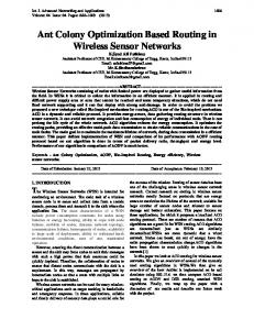
Figure 1: Optimizer System Diagram the overall problem solution. However, our previous results have shown that the effects of this approximation are insignificant whereas the computation saving is large [26]. Planning for problem instances which span periods of time much longer than the planning and execution horizons are naturally handled with a rolling window of aircraft. The idea is that aircraft are able to enter and leave the problem between plans, meaning the optimization is only ever looking at a ‘window’ of the total number of aircraft in the global problem. This is especially well suited to the continuous nature of traffic at airports, with aircraft continuously arriving and departing. Aircraft are considered to be ‘active’ in the optimization for a horizon if they are already taxiing or their earliest possible taxi start time is within the execution horizon. When the aircraft take off, they are removed from the active set before the next horizon is optimized. The planning solution for each horizon is provided by an optimizer which iterates on the conflict prevention constraints, this idea is similar to that presented by Earl and d’Andrea [24]. Initially no constraints are included to prevent conflict on the airport surface. Once the problem is solved, the solution is checked for any conflicts between aircraft. If conflicts are detected, constraints to
8
prevent these are added to the problem and it is re-solved. This is repeated until the solution is conflict free, as shown by the system diagram in Fig. 1. The formulation of this iterative optimizer is described in the remainder of this section. A simulator is used to predict the new state of each aircraft at the end of the current execution horizon, defining the inputs for the optimization at the next planning step. In this paper the simulator assumes that all aircraft behave perfectly, and no variability is introduced. The RH formulation introduces feedback, meaning that the method can in principal compensate for uncertainty.
2.2 2.2.1
Input parameters Airport
The airport surface is modelled as a graph (see Fig. 3) containing a set of Nn nodes denoted N , each representing a junction or intersection of taxiways. A base binary connectivity matrix C is defined such that C(n, m) = 1 if and only if there is a direct taxiway connection from node n to node m on the airport surface. A similarly defined aircraft specific connectivity matrix Ca allows for variations in allowable taxiways between aircraft. The distance matrix L is defined such that L(n, m) represents the distance along the taxiway between adjacent nodes n and m. The shortest taxiway distance from node n to any other node m is defined as rST (n, m). This quantity is precalculated outside the optimization using a rapid graph search algorithm. A set of ‘gate entry’ nodes G ⊂ {n : n ∈ N } are defined, these represent gateways beyond which are apron areas with the parking positions: we do not model the apron area in detail. Designate the departure runway node as nRd ∈ N and the arrival runway node as nRa ∈ N . At present mixed mode runways (including the runway crossing mode) are not being considered.
9
2.2.2
Aircraft
The set A contains all Na active aircraft in the problem, as explained, those which can taxi within the execution horizon. A is composed of an active arriving aircraft set Aarr ⊂ A, and an active departing aircraft set Adep ⊂ A where Aarr = A \ (Adep ). Active aircraft are modelled as points moving along the arcs, subject to a maximum speed limit V (a). Each active aircraft a ∈ A is required to move from its specified origin node n0 (a) ∈ N for the horizon to its final destination node nD (a) ∈ N . No aircraft is permitted to move until after its origin time t0 (a). In their initial horizon this is earliest push-back for departing aircraft and landing time for arriving aircraft, whereas in any subsequent horizon the horizon start time is used. Consideration is not given in this paper to scheduling of the arrival runway, hence the landing times of arriving aircraft are currently assumed to be fixed inputs.
2.2.3
Separation Rules
The matrix dt ∈