66
IEEE TRANSACTIONS ON SUSTAINABLE ENERGY, VOL. 1, NO. 2, JULY 2010
Optimization of Wind Turbine Performance With Data-Driven Models Andrew Kusiak, Member, IEEE, Zijun Zhang, and Mingyang Li, Student Member, IEEE
Abstract—This paper presents a multiobjective optimization model of wind turbine performance. Three different objectives, wind power output, vibration of drive train, and vibration of tower, are used to evaluate the wind turbine performance. Neural network models are developed to capture dynamic equations modeling wind turbine performance. Due to the complexity and nonlinearity of these models, an evolutionary strategy algorithm is used to solve the multiobjective optimization problem. Data sets at two different frequencies, 10 s and 1 min, are used in this study. Computational results with the two data sets are reported. Analysis of these results points to a reduction of wind turbine vibrations potentially larger than the gains reported in the paper. This is due to the fact that vibrations may occur at frequencies higher than ones reflected in the 10-s data collected according to the standard practice used in the wind industry. Index Terms—Blade pitch angle, data analysis, data mining, drive train acceleration, evolutionary strategy (ES) algorithm, multiobjective optimization, neural networks (NNs), power optimization, torque, tower acceleration, wind turbine vibrations.
I. INTRODUCTION NTEREST in renewable energy has increased in recent years due to environmental concerns and growing awareness of the limited supply of fossil fuels. The anticipated increase in the cost of electricity generated from fossil fuels due to carbon taxation has become a catalyst in the quest for clean energy. Wind energy has been most successfully commercialized among all forms of renewable energy.1 Research in wind energy has significantly intensified in recent years. Areas with the most research progress include the design of wind turbines [1], [2], the design and reliability of wind farms [3]–[5], the control of wind turbines [6], [7], [22], [23], wind energy conversion [8], [9], the prediction of wind power [10], [11], and condition monitoring of wind turbines [12], [13]. Optimization has been considered as one critical issue tightly involved in these wind energy research areas. Boukhezzar et al. [27] designed a nonlinear controller for optimizing the power of the DFIG generator [27]. Abdelli et al. [28] applied a multiobjective
I
Manuscript received November 07, 2009; revised February 06, 2010; accepted March 21, 2010. Date of publication April 12, 2010; date of current version June 23, 2010. This work was supported by funding from the Iowa Energy Center under Grant 07-01. The authors are with the Intelligent Systems Laboratory, The University of Iowa, Iowa City, IA 52242 USA (e-mail:
[email protected]). Color versions of one or more of the figures in this paper are available online at http://ieeexplore.ieee.org. Digital Object Identifier 10.1109/TSTE.2010.2046919 1Available:
http://en.wikipedia.org/wiki/Wind_power.
genetic algorithm to optimize the efficiency of a small-scale turbine. The goal of this paper is to model and optimize wind turbine performance in three objectives, maximization of the power produced by a wind turbine, and minimization of vibrations of the turbine’s drive train and tower. Numerous studies of wind power models have been reported in the literature [27], [29]. A passive control method using a tuned mass damper to mitigate vibrations of the blades and tower of a wind turbine was presented in [14]. The research reported in [15] discussed the estimation of aero-elastic damping of operational wind turbine modes based on experiments. The majority of the published research falls into parametric and physics-based models. This paper illustrates nonlinear and nonparametric models for optimization of wind power and vibration using a data-driven approach. Such an approach has been successfully applied to optimize power plants and industrial processes [32]. The sources of wind turbine vibrations [25] are diverse. The focus of this paper is on vibrations attributed to the control of wind turbines, e.g., control of the generator torque and blade pitch. Two parameters, drive train acceleration and tower acceleration, are selected to represent vibrations of the drive train and tower. Two data-driven models of wind turbine vibrations are developed, one to predict the drive train accelerations and the other to predict the tower accelerations. The power output is also modeled by a similar methodology. Neural network (NN) [16]–[18] is applied to extract these data-driven models from industrial (wind turbine) data. The three models are then integrated into a multiobjective optimization model [19]. As the models are nonparametric and nonlinear, obtaining analytical form solutions is difficult, and therefore, an evolutionary strategy (ES) algorithm [20], [21], [26] is used to solve them. Different control preferences lead to numerous control strategies. The data used in this research was obtained from a large (150 MW) wind farm, and its sampling frequency is 0.1 Hz. Since the frequency of wind turbine vibrations is higher than 0.1 Hz, the information loss due to the low (0.1 Hz) frequency of available data has been reflected in the research results. To address the information loss, a 1-min (lower frequency) data set is derived from the 0.1-Hz (10-s) data set. Computational experiments with the two data sets, i.e., 10 s and 1 min, demonstrated a potential for further reduction of turbine vibrations. Due to the limited data frequency, this paper investigates the potential for vibration reduction by adjusting certain controllable parameters, such as blade pitch angle and generator torque. Industrial implementation of the approach proposed in this paper calls for higher frequency data.
1949-3029/$26.00 © 2010 IEEE Authorized licensed use limited to: The University of Iowa. Downloaded on June 25,2010 at 17:49:01 UTC from IEEE Xplore. Restrictions apply.
KUSIAK et al.: OPTIMIZATION OF WIND TURBINE PERFORMANCE WITH DATA-DRIVEN MODELS
TABLE I SAMPLE DATA SET OF 10-s DATA COLLECTED BY SCADA SYSTEM
67
the two is used in this paper. The vibration of the drive train system is expressed as
(1) TABLE II SAMPLE 1-min DATA COMPUTED BASED ON THE 10-s DATA
II. MODELING WIND TURBINE VIBRATIONS AND POWER OUTPUT
where all parameters are time dependent, and represents the drive train vibrations; is the wind speed, is the torque, is the blade pitch angle, and is the previous sampling time period. Parameter selection is mainly based on domain knowledge. Details are presented in Table VIII. In addition, the symbol represents model (1) derived from the data with an NN algorithm. 2) Tower Vibration Model: The sensor to measure tower acceleration is located near the connection of a nacelle and a tower. The model of a tower vibration is presented in
A. Data Description Two types of data sets, 10-s data and 1-min data of a wind turbine, are used in this research. The 10-s data was collected from a supervisory control and data acquisition (SCADA) system, and the 1-min data set was derived by averaging the values of all parameters across each 60-s period from the 10-s data set. The total length of each data set is two months. The SCADA system contains values of more than 120 parameters; however, only certain parameters that could be potentially related to wind turbine vibrations and their power output were selected based on the domain expertise and past studies in wind energy. Tables I and II demonstrate the general format of the data sets used in this research. The columns in Tables I and II represent the parameters related to wind turbine vibrations and the power output. All data is time stamped.
(2) The parameters of model (2) are identical to those in model (1) with representing the tower vibrations. The symbol is used to represent model (2) extracted with an NN. In models (1) and (2), the torque value at time and blade at time are considered as controllable parampitch angle eters used to realize the potential for controlling vibrations of a wind turbine. Wind speed at time and the past states of all parameters are considered as noncontrollable parameters. D. Power Output Model It is known that the power extracted from the wind is expressed as the nonlinear expression
B. Data Preprocessing Data preprocessing is critical to the data mining for correctness and accuracy of the results. Some of the data errors may have been caused by sensor failures, transmission errors, and failures of various subsystems. The errors usually appear as data exceeding physical constraints or missing values. All incorrect data were deleted from the data sets used in this paper. C. Wind Turbine Vibration Model In this paper, understanding and modeling vibrations of a wind turbine from the operational data collected from the turbine are presented. Two significant vibration sources are considered: vibrations due to the air passing through the wind turbine and vibrations due to the forces originating with the control system that affect the torque and the blade pitch angle. The values of the drive train acceleration recorded by the SCADA system are used to represent the vibration of the drive train of a wind turbine, while the tower vibration is represented by the acceleration measurements from the tower. 1) Drive Train Vibration Model: In this research, drive train part acceleration is measured by a sensor installed at the bottom back of a nacelle. Since two identical drive train acceleration values are reported by the SCADA system, an average value of
(3) where the air flow density is represented by , is the rotor rais the power coefficient dius, is the wind speed, and function of the blade pitch angle and the tip-speed ratio . Model (3) does not exactly match the actual power curve illustrated in Fig. 1. In this power curve, a given wind speed value is mapped onto a range of power values for a variety of reasons, including sensor errors and faults of various types; for example, a small error in wind speed could result in a large error of the power output due to the cube relationship. To model actual power curves, neural networks, -NN ( nearest neighbor) and other data-mining algorithms can be used. In this paper, an NN is used to estimate power output, and it is expressed model as (4) The notation used here is identical to the notation of model (1). E. Validation of the Models The accelerometers measuring accelerations are sensitive to noise, and therefore, wavelet analysis is applied to denoise the
Authorized licensed use limited to: The University of Iowa. Downloaded on June 25,2010 at 17:49:01 UTC from IEEE Xplore. Restrictions apply.
68
IEEE TRANSACTIONS ON SUSTAINABLE ENERGY, VOL. 1, NO. 2, JULY 2010
TABLE IV TRAINING RESULTS OF THE NN MODEL
TABLE V TEST RESULTS OF THE NN MODEL
Fig. 1. Prediction with a data-driven time-series models.
TABLE III MEAN SHIFT OF THE NOISED DRIVE TRAIN ACCELERATION
measured drive train and tower accelerations. This improves stability of the models extracted by the data-mining algorithms. Comparative analysis is discussed to select the most appropriate combination of order and level Daubechies wavelets [30], namely DB7 Level 10, DB7 Level 7, and DB5 Level 5. The difference between the mean of the original and denoised data (mean shift) is used as the selection criterion in the comparative analysis. A smaller mean shift is favored in data smoothing. Table III shows the difference between the mean shift of the drive train acceleration for three combinations of the wavelet order and level. The data set from 10/1/2008 12:00:10 A.M. to 10/8/2008 12:00:00 A.M. has been selected in this analysis. As shown in Table III, DB5 Level 5 is selected based on its smallest mean shift. To illustrate the value of data denoising, two experiments are developed. An NN is applied to extract models based on the original data and the data denoised by DB5 Level 5 for drive train acceleration. Training and test results of the experiments are presented in Tables IV and V, respectively. Four metrics (5)–(8), shown at the bottom of the page, are used to evaluate the performance of the data-derived models, the mean absolute error (MAE), the standard deviation of mean absolute error (SD of MAE), the mean absolute percentage
error (MAPE), and the standard deviation of mean absolute is the value of th percentage error (SD of MAPE) where is the observed value of th instance predicted by the NN, instance, and means the total number of instances in the data set. Based on results in Tables IV and V, it is obvious that denoising and smoothing data is beneficial for modeling. The large MAPE and SD of MAPE for the original dataset in Table IV are caused by the small values in the training set and the nature of these two metrics. For example, some instances with values as small as 0.00002 are contained. A small error (the difference between the observed and predicted value) such as 2 results in a large MAPE of (7) and a large SD of MAPE in (8). To build data-driven models, the 10-s and 1-min data sets are divided into a training data set (2/3 of all data) and a test data set (1/3) of all data. In the 10-s data set, there are a total of 204 894 instances, and in the 1-min data there are a total of 34 149 instances. Each training data set is used to train an NN, while the test data set is used to test the accuracy of data-derived models. Four metrics (5)–(8) are used to evaluate the quality of models. Table VI presents the test results of three NN models extracted from the 10-s data set. The mean value of the drive train acceleration in this data set is 67.24 and the standard deviation (SD) of the drive train acceleration is 36.81. As shown in Table VI, the MAE of the drive train acceleration predicted by the NN model is 1.27, the corresponding MAPE is 0.02, which means that the model is 98% accurate. For the tower acceleration, the mean value of the tower acceleration is 72.83 and the
(5)
(6) (7)
(8)
Authorized licensed use limited to: The University of Iowa. Downloaded on June 25,2010 at 17:49:01 UTC from IEEE Xplore. Restrictions apply.
KUSIAK et al.: OPTIMIZATION OF WIND TURBINE PERFORMANCE WITH DATA-DRIVEN MODELS
TABLE VI TEST RESULTS OF THE NN MODELS FOR 10-s DATA
Fig. 2. First 50 test points of the drive train acceleration for 10-s data.
Fig. 3. First 50 test points of the tower acceleration for 10-s data.
Fig. 4. First 50 test points of the power output for 10-s data.
SD is 45.40. The MAE in predicting tower acceleration is 4.73 and the SD is 8.92. The MAPE is 0.06, i.e., the model is 94% accurate. Although the MAPE is quite impressive, the SD of MAPE, which equals 0.10, is somewhat large. This indicates that the accuracy of the model predicting tower acceleration is not steady. However, considering the complexity of the tower acceleration itself, this result is acceptable for tower vibration analysis. The mean value of the power generated is 633.83 and the SD is 460.36. The MAE of the model predicting power is 9.86. The corresponding MAPE for the power prediction is 0.03, i.e., the model is 97% accurate. Figs. 2–4 illustrate the first 50 predicted and observed values of the 10-s test data set for the three models: drive train acceleration (Fig. 2), tower acceleration (Fig. 3), and power (Fig. 4).
69
TABLE VII TESTING RESULTS OF THE NN MODELS FOR 1-min DATA
Fig. 5. First 50 test points of the drive train acceleration for 1-min data.
Fig. 6. First 50 test points of the tower acceleration for 1-min data.
The test results for three models extracted from the 1-min data set are included in Table VII. The MAE of the drive train acceleration is 0.77, and the MAPE of 0.01 implies a 99% accuracy of the model. For the model to predict the tower acceleration, the MAPE is 0.03, i.e., the model is 97% accurate. The MAPE of the model predicting the generated power is 0.03 (97% model accuracy). Although the model accuracy is impressive, the SD is relatively high. The results indicate that even though the models can quite accurately predict acceleration and power output, some predicted instances could involve a significant error. Fig. 5 presents the first 50 points of the observed and predicted values of the drive train accelerations. Fig. 6 illustrates the first 50 points for the tower acceleration, and Fig. 7 shows the power prediction results. III. MULTIOBJECTIVE OPTIMIZATION MODEL In modeling vibrations and power output, torque and blade pitch angle are considered as controllable parameters. Parameters such as wind speed and past states of noncontrollable parameters serve as inputs to the data-driven models. Both the generator torque and the blade pitch angle impact vibrations of the drive train and the tower. In the model considered in this paper, the drive train acceleration, the tower acceleration, and the inverse of power output are the three objectives to be minimized. Solutions of this model
Authorized licensed use limited to: The University of Iowa. Downloaded on June 25,2010 at 17:49:01 UTC from IEEE Xplore. Restrictions apply.
70
IEEE TRANSACTIONS ON SUSTAINABLE ENERGY, VOL. 1, NO. 2, JULY 2010
TABLE IX DESCRIPTION OF PARAMETERS
Fig. 7. First 50 test points of the power output 1-min data.
TABLE VIII DESCRIPTION OF PARAMETERS
become control strategies for the wind turbine. This multiobjective minimization model is formulated in (9), shown at the , , and bottom of the page, where are the three objectives to be minimized. Table VIII lists all parameters used in model (9). The first three parameters in Table VIII represent the three objectives to and , are be minimized. Two controllable parameters, the torque and the blade pitch angle at time . The remaining variables on the list in Table VIII are the noncontrollable pa. rameters at time and The two inequality constraints in model (9) impose the upper and lower bounds on the two controllable parameters, i.e., they define the feasible ranges for these at parameters. The range for the torque value
time
is between
and . The torque value was . The change of the torque normalized in the interval value in two consecutive time intervals (10 s or 1 min) is limited to 50% of the maximal torque. This value is determined by considering the turbine specifications and realistic control. Based on manufacturing specifications, the generator torque is limited to 10 090 Nm, and the maximum change rate of the torque is 4500 Nm/s, which corresponds to 45% of the maximum torque per second. The average blade pitch angle at time is in the range and . The values of the blade pitch angle change in the interval . The values were determined based on the maximum and minimum value of the blade pitch angle in the data set considered in this research. The maximum one time (10-s or 1-min) change of the blade pitch angle is fixed at 5 . Table IX provides correlation coefficients [24] between controllable parameters and the three parameters considered as the model objectives, i.e., drive train acceleration, tower acceleration, and power. Although the relationship between these parameters is nonlinear, the linear relationship expressed with the correlation coefficient provides certain insights into dependencies among them. As illustrated in Table IX, torque and blade pitch angle are correlated to a different degree to the three parameters in the model’s objective. These correlation coefficients indicate that changing the values of the torque and the blade pitch angle impacts power output, drive train acceleration, and tower acceleration simultaneously. Thus, optimization of the trade-off between vibrations and power becomes a challenge. To recognize the importance of the three model objectives in model (9), a weighted sum of these objectives is presented
(9)
Authorized licensed use limited to: The University of Iowa. Downloaded on June 25,2010 at 17:49:01 UTC from IEEE Xplore. Restrictions apply.
KUSIAK et al.: OPTIMIZATION OF WIND TURBINE PERFORMANCE WITH DATA-DRIVEN MODELS
in (10), shown at the bottom of the page. The weights indicate different control preferences. The notation is the same as in model (9). The weight assignment to the objectives serves as a mechanism for solution selection among many nondominant solutions contained in the Pareto set.
71
TABLE X TWO EXPERIMENTS FOR TUNING SP AND POPULATION SIZE
IV. SOLVING THE MULTIOBJECTIVE OPTIMIZATION MODEL A. Evolutionary Algorithm Model (9) is learned by an NN rather than provided in an analytical form. To solve this multiobjective minimization model, evolutionary algorithms are the most natural choice. Here a particular ES algorithm, the Strength Pareto Evolutionary Algorithm (SPEA) [20], is used to solve model (9). The solutions to the multiobjective minimization model (9), the torque value and the blade pitch angle, are encoded as vectors. These solutions are treated as individuals defined as at the th generation, where and . The elements and of the solution represent the torque and the blade pitch angle at the vector th generation. The parameter represents the vector of SDs of the normal distribution with mean equal to zero. In this and are the SDs associated with torque and blade vector, and , pitch angle. Two uniform distributions, are applied to initialize the values of elements in the vector of SDs . Offspring (children) in SPEA are then produced by recombination of parents and the mutation procedure presented in [31]. B. Tuning Parameters of the ES Algorithm Numerous SPEA parameters need to be determined ahead of computation. In this research, parameters such as , , tournament size, and the number of parents used in recombination, are arbitrarily selected, as they do not significantly impact computa, the tournament tional results. The value of is 0.5, size is four, and the number of recombined parents is two. Besides these parameters, the value of two other parameters needs to be determined: the selection pressure (SP) and the population size. The SP is the ratio of the parent set size divided by the size of the offspring set (11)
where SP the selection pressure, the size of parent set , and the size of offspring set . Two experiments are conducted to tune SP and population size of the ES algorithm applied to 10-s and 1-min data sets. Table X presents details of the two experiments. Ten different SPs are considered: SP-1 (2parents/2offspring), SP-2 (2parents/4offspring), SP-3 (2parents/6offspring), SP-4 (2parents/8offspring), SP-5 (2parents/10offspring), SP-6 (2parents/12offspring), SP-7 (2parents/14offspring), SP-8 (2parents/16offspring), SP-9 (2parents/18offspring), and SP-10 (2parents/20offspring). Three extreme cases of the SP accelerating the convergence of the ES algorithm are considered, minimizing the drive train acceleration only (Case 1), minimizing the tower acceleration only (Case 2), and minimizing the inverse of power only (Case 3). These three extreme cases can be expressed with three weight , , assignments used in model (10). In Case 1, ; in Case 2, , , and ; and in and , , and . Case 3, Table XI illustrates the convergence of the ES algorithm as a function of the SP for experiment 1. To determine the best SP, the ES algorithm has run for 1500 generations for each SP. As shown in Table XI, the fastest average convergence of the ES algorithm corresponds to SP-9. The ES algorithm converges in Case 1 at the 106th generation. It is observed that the ES algorithm converges at the 180th and 41st generation in Case 2 and Case 3, respectively. The selection pressure SP-9 in Table XI involves the smallest average number of generations at 109.
(10)
Authorized licensed use limited to: The University of Iowa. Downloaded on June 25,2010 at 17:49:01 UTC from IEEE Xplore. Restrictions apply.
72
IEEE TRANSACTIONS ON SUSTAINABLE ENERGY, VOL. 1, NO. 2, JULY 2010
TABLE XI CONVERGENCE FOR 10 VALUES OF THE SP IN EXPERIMENT 1
TABLE XIII CONVERGENCE OF THE ES ALGORITHM FOR TWO POPULATIONS OF EXPERIMENT 1
TABLE XIV CONVERGENCE OF THE ES ALGORITHM FOR TWO POPULATIONS OF EXPERIMENT 2
TABLE XII CONVERGENCE FOR 10 VALUES OF THE SP IN EXPERIMENT 2
V. COMPUTATIONAL RESULTS Three types of computational results will be discussed in this section. First, the results of a single-point optimization based on the 10-s data set are introduced. Then, the optimization results over a period of 11 min (multipoint) are presented for three extreme cases, which are defined later in this section. Finally, a comparison between the optimization for the 10-s data set and 1-min data set is discussed to demonstrate the impact on mitigating wind turbine vibrations over a 10-min period. A. Single-Point Optimization
Table XII illustrates the convergence for different values of the SP in experiment 2 with the best convergence attained for SP-10. The ES algorithm in Cases 1 and 2 converges at the 36th generation and in Case 3 at the 55th generation. In addition to the analysis of the SP, two population sizes for each experiment are evaluated, where one of them is five times larger than the base population. For example, the two populations in experiment 1 are denoted as PS1 (2 parents/18 offspring) and PS2 (10 parents/90 offspring). Larger population sizes are not considered here due to the excessive computational cost of the ES algorithm. Table XIII illustrates the convergence of the ES algorithm for two population sizes of experiment 1. As shown in Table XIII, the fastest convergence is attained for population size PS2 with 10 parents and 90 offspring. The minimum inverse of power (Case 3) is attained at the first generation. The latter is due to the fact that the maximum torque value was included in the initial solution. In Cases 1 and 2, the ES algorithm converges at the 18th and 51st generation. In this experiment, the average number of generations was much lower than for the case with a population size of 2 parents and 18 offspring (see Table XIII). Table XIV shows that the population with 2 parents and 20 offspring leads to the best performance in experiment 2. For this population size, the ES algorithm converges at the 36th generation in Case 1. It also converges at the 36th generation in Case 2, and in Case 3 at the 55th generation.
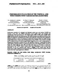
Optimizing a trade-off between wind turbine vibrations and the power output produces a set of nondominant solutions. An instance of the 10-s data set shown in Table X is selected to compute the solution set. Table XV presents a partial solution set for this instance. As presented in Table X, the original average drive train acceleration is 147.43, the original tower acceleration is 164.64, and the original generated power is 1484.47. Each solution in Table XV represents different settings of torque value (TV) and blade pitch angle (BPA). For example, Solution 4 in Table XV shows that for the torque value (TV) of 67.6 and blade pitch angle (BPA) at 15, the average drive train acceleration is reduced from 147.43 to 136.71, and the tower acceleration could be reduced from 164.64 to 120.34. However, the turbine generated power is reduced from 1484.47 to 1031.21. Under this control strategy, the respective gains of the drive train acceleration and the tower acceleration are 7.27% and 26.90%, respectively. However, the reduced vibrations also reduced the power output by 30.53%. Solution 7 illustrates a modest gain in tower accelerations. As presented in Table XV, the tower accelerations are reduced from 164.64 to 119.41, i.e., the gain is 27.48%. Simultaneously, the drive train acceleration is reduced from 147.43 to 136.98, and the turbine generated power is reduced from 1484.47 to 1005.11. The respective gains are 7.09% and 32.29%. Fig. 8 shows the values of three objective functions produced by nondominated solutions of the elite set in a three-dimensional space. The vertical axis represents power output. One horizontal axis represents the drive train acceleration and the other represents the tower acceleration. The elite set characterizes the
Authorized licensed use limited to: The University of Iowa. Downloaded on June 25,2010 at 17:49:01 UTC from IEEE Xplore. Restrictions apply.
KUSIAK et al.: OPTIMIZATION OF WIND TURBINE PERFORMANCE WITH DATA-DRIVEN MODELS
73
TABLE XV CONVERGENCE FOR 10 VALUES OF THE SP IN EXPERIMENT 2
Fig. 9. Optimized and original drive train acceleration of Case 1 for 10-s data.
Fig. 10. Computed and original torque value of Case 1 for 10-s data.
Fig. 8. Pareto optimal fronts.
Pareto front and represents the best solutions satisfying the three objective functions simultaneously. B. Multipoint Optimization The results presented in Table XV involved one instance only. In this section, multipoint optimization will be introduced, and the same three cases discussed in Section IV-B are considered. The data from 10/19/08 2:43:00 A.M. to 10/19/08 2:54:00 A.M. (a total of 11 min of 10-s data) are used in this study. Optimization results for three cases are presented. Fig. 9 illustrates the optimization results of Case 1. The corresponding control strategies are illustrated in Figs. 10 and 11. Fig. 10 shows the original and computed torque. Fig. 11 illustrates the original and the computed blade pitch angle. The mean reduction of the drive train acceleration over the 11-min time period is shown in Table XVI. The mean of the drive train acceleration has been reduced from 131.67 to 119.67 (a 9.16% gain). Fig. 12 presents the results of Case 2. Fig. 13 illustrates the computed torque and the original torque. Fig. 14 shows the computed blade pitch angle (controls) and the original blade pitch angle. In controlling the tower vibrations, the value of torque and blade pitch angle should both be decreased at the same time. Table XVII presents the mean gain of reduced tower accelerations over the 11-min period. The mean value of minimum
Fig. 11. Computed and original blade pitch angle of Case 1 for 10-s data.
TABLE XVI GAINS IN VIBRATION REDUCTIONS OF THE DRIVE TRAIN FOR CASE 1
tower acceleration is 86.38. The mean of the original tower acceleration is 127.47. The tower acceleration has been reduced by 32.23%. Fig. 15 shows the optimization results for Case 3 over the 11-min period. The original and computed values of the torque and the blade pitch angle are shown in Figs. 16 and 17, respectively. In this case, the simulation results indicate that to obtain the maximum power, output does not necessarily require a maximum torque value but an increase of the mean blade pitch angle. Table XVIII shows a mean gain of 1.05% in maximizing power output. The average of the maximized power output shown in Table XVIII is 1498.02, and the mean original power output is 1482.42. In this section, only three sets of weight assignments for the multiobjective optimization model were considered. Methods
Authorized licensed use limited to: The University of Iowa. Downloaded on June 25,2010 at 17:49:01 UTC from IEEE Xplore. Restrictions apply.
74
IEEE TRANSACTIONS ON SUSTAINABLE ENERGY, VOL. 1, NO. 2, JULY 2010
Fig. 12. Optimized and original tower acceleration of Case 2 for 10-s data.
Fig. 16. Computed and original torque value of Case 3 for 10-s data.
Fig. 13. Computed and original torque value of Case 2 for 10-s data. Fig. 17. Computed and original blade pitch angle of Case 3 for 10-s data.
TABLE XVIII GAINS IN POWER OUTPUT FOR CONTROL STRATEGY OF CASE 3
C. Comparison of Computational Results
Fig. 14. Computed and original blade pitch angle of Case 2 for 10-s data.
TABLE XVII GAIN IN REDUCTION TOWER VIBRATIONS FOR CASE 2
Fig. 15. Optimized and original power output of Case 3 for 10-s data.
for optimal generation of weights need to be considered in the future.
In this section, computational experience with 10-s and 1-min data sets is presented. The information loss due to the reduced data sampling frequency is addressed. The results (all mean values) included in Table XIX summarize the gains in vibration reduction due to increased data sampling frequency by considering three cases for two types of data sets. Ten minutes worth of 10-s data (from 10/19/2008 2:43:00 A.M. to 10/19/2008 2:52:50 A.M.) were selected, and the mean gains are compared to the results obtained of the same 1-min data. Table XIX illustrates that the gain in reduction of the drive train vibration based on the model extracted from 10-s data is 9.10%. This gain is larger than the one for the model extracted from the 1-min data set (5.87%). For Case 2, shown in Table XIX, the mean reduction of the tower acceleration for the 10-s data set is 31.76%, and the mean gain for the 1-min data set is 18.46%. Even though in Case 3 the gain of the power output for the 10-s data set is larger than the gain of the power for the 1-min data set, it is not as significant as the gain in reducing vibrations. This is due to the different characteristics of the power output and vibration in high frequency, as well as the bounded wind turbine power, here at 1.5 MW. These results indicate that using the current data frequency (0.1 Hz) could limit even larger gains in vibrations. Using higher frequency data would likely unleash additional gains in vibrations reduction. The accelerometer and the SCADA system available for this research are typical of the
Authorized licensed use limited to: The University of Iowa. Downloaded on June 25,2010 at 17:49:01 UTC from IEEE Xplore. Restrictions apply.
KUSIAK et al.: OPTIMIZATION OF WIND TURBINE PERFORMANCE WITH DATA-DRIVEN MODELS
TABLE XIX COMPARISON OF COMPUTATIONAL RESULTS FOR 10-s DATA SET AND 1-min DATA SET OVER 10-min HORIZON
75
The objective of this paper, building accurate data-driven models to study the impact of turbine control on their vibrations and power output and demonstrating the optimization results of wind turbine performance, was accomplished. REFERENCES
present industrial standard and did not offer higher frequency vibration data. VI. CONCLUSION In this paper, a multiobjective optimization model involving wind turbine power output, vibration of drive train, and vibration of tower was studied. A data-driven approach for model development was introduced. The drive train vibration and tower acceleration were represented with accelerations of the drive train and the tower. Models developed for prediction of vibrations and the power produced by the turbine were trained by NN and were accurate. Although the power output was considered as an objective, it also served as a bound constraining the mitigation aimed at curtailing drive train vibration and tower vibration. Industrial data sets used in the study were collected by an SCADA system. The original data set was sampled at 10-s intervals (0.1-Hz frequency). Although the research showed that the data collected by the industry-accepted frequency could not be sufficient to fully mitigate turbine vibrations, the methodology presented in this paper could be used once suitable data becomes available. Bounded by the data availability, a 1-min data set was derived by averaging instances in the original 10-s data set. Both data sets were used to model drive train vibration, tower vibration, and the power output of a wind turbine. The prediction accuracy of the derived models was tested with independent data sets. Four metrics, MAE, SD of MAE, MAPE, and SD of MAPE, all defined in the paper, were introduced to evaluate the performance of data-driven models. Comparative study of computational experiments demonstrated that the potential to reduce vibration of the drive train and tower by optimized control. The multiobjective optimization model was solved with an ES algorithm. The impact of SP and population size on the efficiency of the ES algorithm was studied. The optimization results generated based on three weight assignment cases presented the potential gains of vibration mitigation and power maximization by adjusting two controllable variables, the generator torque and the blade pitch angle. The computational results demonstrated that the gains in reduced wind turbine vibrations and increased power output were larger for the 10-s data sets than those for the 1-min data sets. All 1-min data sets were obtained by averaging the corresponding 10-s data.
[1] D. Laino, C. Butterfield, R. Thresher, and D. Dodge, “Evaluation of select IEC standard wind turbine design cases on the combined experiment wind turbine model,” Wind Energy, vol. 14, pp. 47–48, 1993, American Society of Mechanical Engineers, Solar Energy Division (Publication) SED. [2] K. Saranyasoontorn and L. Manuel, “A comparison of wind turbine design loads in different environments using inverse reliability techniques,” Wind Energy, vol. 126, no. 4, pp. 1060–1068, 2004. [3] R. Barthelmie, S. Frandsen, M. Nielsen, S. Pryor, P. Rethore, and H. Jørgensen, “Modelling and measurements of power losses and turbulence intensity in wind turbine wakes at Middelgrunden offshore wind farm,” Wind Energy, vol. 10, no. 6, pp. 517–528, 2007. [4] J. Moran, J. Barón, J. Santos, and M. Payán, “An evolutive algorithm for wind farm optimal design,” Neurocomputing, vol. 70, no. 16, pp. 2651–2658, 2007. [5] A. Leite, C. Borges, and D. Falcão, “Probabilistic wind farms generation model for reliability studies applied to Brazilian sites,” IEEE Trans. Power Syst., vol. 21, no. 4, pp. 1493–1501, Nov. 2006. [6] T. Senjyu, R. Sakamoto, N. Urasaki, T. Funabashi, H. Fujita, and H. Sekine, “Output power leveling of wind turbine generator for all operating regions by pitch angle control,” IEEE Trans. Energy Convers., vol. 21, no. 2, pp. 467–475, Jun. 2006. [7] H. Ko, K. Lee, M. Kang, and H. Kim, “Power quality control of an autonomous wind-diesel power system based on hybrid intelligent controller,” Neural Netw., vol. 21, no. 10, pp. 1439–1446, 2008. [8] M. Arifujjaman, M. Iqbal, and J. Quaicoe, “Performance comparison of grid connected small wind energy conversion systems,” Wind Eng., vol. 33, no. 1, pp. 1–18, 2009. [9] Ö Mutlu, E. Akpinar, and A. Balikci, “Power quality analysis of wind farm connected to Alaçati substation in Turkey,” Renewable Energy, vol. 34, no. 5, pp. 1312–1318, 2009. [10] A. Kusiak, H. Zheng, and Z. Song, “Wind farm power prediction: A data-mining approach,” Wind Energy, vol. 12, no. 3, pp. 275–293, 2009. [11] A. Kusiak, H. Zheng, and Z. Song, “Short-term prediction of wind farm power: A data-mining approach,” IEEE Trans. Energy Convers., vol. 24, no. 1, pp. 125–136, Mar. 2009. [12] A. Kusiak, H. Zheng, and Z. Song, “On-line monitoring of power curves,” Renewable Energy, vol. 34, no. 6, pp. 1487–1493, 2009. [13] A. Kusiak, H. Zheng, and Z. Song, “Models for monitoring wind farm power,” Renewable Energy, vol. 34, no. 3, pp. 583–590, 2009. [14] P. J. Murtagh, A. Ghosh, B. Basu, and B. Broderick, “Passive control of wind turbine vibrations including blade/tower interaction and rotationally sampled turbulence,” Wind Energy, vol. 11, no. 4, pp. 305–317, 2008. [15] M. H. Hansen, K. Thomsen, P. Fuglsang, and T. Knudsen, “Two methods for estimating aeroelastic damping of operational wind turbine modes from experiments,” Wind Energy, vol. 9, no. 1–2, pp. 179–191, 2006. [16] H. Siegelmann and E. Sontag, “Analog computation via neural networks,” Theor. Comput. Sci., vol. 131, no. 2, pp. 331–360, 1994. [17] G. P. Liu, Nonlinear Identification and Control: A Neural Network Approach. London: Springer, 2001. [18] M. Smith, Neural Networks for Statistical Modeling. New York: Van Nostrand Reinhold, 1993. [19] R. Steuer, Multiple Criteria Optimization: Theory, Computations, and Application. New York: Wiley, 1986. [20] E. Zitzler and L. Thiele, “Multiobjective evolutionary algorithms: A comparative case study and the strength Pareto approach,” IEEE Trans. Evol. Comput., vol. 3, no. 4, pp. 257–271, Nov. 1999. [21] Z. Song and A. Kusiak, “Optimization of temporal processes: A modelpredictive control approach,” IEEE Trans. Evol. Comput., vol. 13, no. 1, pp. 169–179, Feb. 2009. [22] K. Johnson, L. Pao, M. Balas, and L. Fingersh, “Control of variablespeed wind turbines: Standard and adaptive techniques for maximizing energy capture,” IEEE Control Syst. Mag., vol. 26, no. 3, pp. 70–81, Jun. 2006. [23] I. Munteanu, N. Cutululis, A. Bratcu, and E. Ceanga, “Optimization of variable speed wind power systems based on a LQG approach,” Control Eng. Practice, vol. 13, no. 7, pp. 903–912, 2005.
Authorized licensed use limited to: The University of Iowa. Downloaded on June 25,2010 at 17:49:01 UTC from IEEE Xplore. Restrictions apply.
76
IEEE TRANSACTIONS ON SUSTAINABLE ENERGY, VOL. 1, NO. 2, JULY 2010
[24] R. A. Fisher, “Frequency distribution of the values of the correlation coefficient in samples from an indefinitely large population,” Biometrika, vol. 10, no. 4, pp. 507–521, 1915. [25] V. Wowk, Machinery Vibration: Measurement and Analysis. New York: McGraw-Hill, 1991. [26] K. Deb, Multi-Objective Optimization Using Evolutionary Algorithms. New York: Wiley, 2001. [27] B. Boukhezzar and H. Siguerdidjane, “Nonlinear control with wind estimation of a DFIG variable speed wind turbine for power capture optimization,” Energy Convers. Manage., vol. 50, no. 4, pp. 885–892, 2009. [28] A. Abdelli, B. Sareni, and X. Roboam, “Optimization of a small passive wind turbine generator with multiobjective genetic algorithms,” Int. J. Appl. Electromagn. Mechanics, vol. 26, no. 3–4, pp. 175–182, 2007. [29] B. Boukhezzar, H. Siguerdidjane, and M. Maureenhand, “Nonlinear control of variable-speed wind turbines for generator torque limiting and power optimization,” J. Solar Energy Eng., vol. 128, no. 4, pp. 516–530, 2006. [30] I. Daubechies, Ten Lectures on Wavelets. Philadelphia, PA: Society for Industrial and Applied Mathematics, 1992. [31] A. Kusiak, Z. Song, and H. Zheng, “Anticipatory control of wind turbines with data-driven predictive models,” IEEE Trans. Energy Convers., vol. 24, no. 3, pp. 766–774, Sep. 2009. [32] Z. Song and A. Kusiak, “Constraint-based control of boiler efficiency: A data-mining approach,” IEEE Trans. Ind. Informat., vol. 3, no. 1, pp. 73–83, Feb. 2007. Andrew Kusiak (M’89) received the B.S. and M.S. degrees in engineering from the Warsaw University of Technology, Warsaw, Poland, in 1972 and 1974, respectively, and the Ph.D. degree in operations research from the Polish Academy of Sciences, Warsaw, in 1979. He is currently a Professor at the Intelligent Systems Laboratory, Department of Mechanical and Industrial Engineering, The University of Iowa, Iowa City. He speaks frequently at international meetings, conducts professional seminars, and does consulta-
tion for industrial corporations. He has served on the editorial boards of over 40 journals. He is the author or coauthor of numerous books and technical papers in journals sponsored by professional societies, such as the Association for the Advancement of Artificial Intelligence, the American Society of Mechanical Engineers, etc. His current research interests include applications of computational intelligence in automation, wind and combustion energy, manufacturing, product development, and healthcare. Prof. Kusiak is an Institute of Industrial Engineers Fellow and the Editor-inChief of the Journal of Intelligent Manufacturing.
Zijun Zhang received the B.S. degree from the Chinese University of Hong Kong, Hong Kong, China, in 2008, the M.S. degree from the University of Iowa, Iowa City, IA, in 2009, and is currently working toward the Ph.D. degree at the Department of Mechanical and Industrial Engineering, The University of Iowa, Iowa City. His research concentrates on data mining and computational intelligence applied to systems modeling and optimization in wind energy and HVAC domains. He is a member of the Intelligent Systems Laboratory at The University of Iowa.
Mingyang Li received the B.S. (2008) degree from the Huazhong University of Science and Technology, Hubei, China, the M.S. (2009) degree from the University of Iowa, Iowa City, IA, and is working toward the Ph.D. degree at the Department of Mechanical and Industrial Engineering, The University of Iowa, Iowa City. His research concentrates on applications of data mining and computational intelligence in system modeling and optimization.
Authorized licensed use limited to: The University of Iowa. Downloaded on June 25,2010 at 17:49:01 UTC from IEEE Xplore. Restrictions apply.