Journal of Renewable Energy and Sustainable Development (RESD)
June 2015 - ISSN 2356-8569
Aerodynamic Optimization of a Wind Turbine Blade Designed for Egypt's Saharan Environment Using a Genetic Algorithm Khaled Yassin, Aya Diab, Zakaria Ghoneim Mechanical Power Engineering Dept. Faculty of Engineering, Ain Shams University Cairo, Egypt
[email protected]
Abstract – This work aims to optimize the aerodynamic parameters (airfoil chord lengths and twist angles smoothed using Bezier curves) of the NREL 5MW wind turbine and a wind turbine designed for site-specific wind conditions to increase the wind turbine's annual energy production (AEP) under this site conditions. This optimization process is carried out using a Genetic Algorithm (GA) developed in MATLAB and coupled with NREL's FAST Modularization Framework. The results showed that after optimizing the NREL 5MW wind turbine design, the AEP was improved by 5.9% of the baseline design AEP, while a site-specific designed wind turbine using Schmitz equations showed 1.2% improvement in AEP. These results show that optimization of wind turbine blade aerodynamic parameters for site-specific wind conditions leads to improvement in AEP and hence decreasing cost of energy generated by wind turbines.
incorporates a target of 1,050 MW wind capacity to be installed by the end of the Sixth Five-Year Plan period (2007-2012). On the long term, the government envisages 20% of electricity to come from renewable energy by 2020. To meet this target, it is expected that 12% will be satisfied by wind power. With Egypt’s wind energy potential and its ambitious plan to expand wind energy contribution in electric energy production, the need to develop its own technology in wind turbine becomes vital. In Egypt, while viable wind farm locations with high quality wind resources exist in the Gulf of Suez region (for example Zaafarana, and Jabal El-Zeit), improved blade design optimized for a particular location can significantly reduce the unit cost of electricity, amortized over the turbine lifetime. This is expected to expand the number of locations that are economically viable, such as the east and the west of the Nile.
Keywords Wind Turbine, aerodynamics, optimization, genetic algorithm, site-specific wind turbine.
In the last few years, the topic of developing and optimization of wind turbine rotors attracted a lot of attention. Maheri et al [1] applied a combined analytical/FEA coupled FSI to design and optimize bend-twist adaptive blades to increase average generated power over the operation wind speed. In their work, shell thickness, ply angles, and pre-twist distribution were optimized to increase the energy generated at this wind speed. Xiong et al.[2] presented an optimization model of HAWT blade using Weibull frequency distribution function (to simulate wind speeds around the year) and extended compact genetic algorithm (ECGA) to optimize airfoil shapes, chord lengths and twist angles of a 1.3 MW turbine blade to maximum annual energy production.
I. INTRODUCTION Wind energy is the fastest growing source of energy in the world today, with an average growth rate of nearly 30% per year over the past 10 years. With global warming, energy security, and rising fuel prices being main public concerns, it is reasonable to assume that the growth of the wind energy industry will continue at an unprecedented pace. The global energy challenge is certainly not foreign to Egypt whose developmental needs mandate the addition of 2000-3000 MW of installed capacity each year. Luckily, Egypt is endowed with an excellent wind energy potential, especially in the Red Sea coast area where a capacity of 20,000 MW could be achieved, as the annual average wind speed is around 10 m/s. Egypt's national energy planning
Xudong et al. [3] presented optimization procedure of wind turbine blade. This procedure includes both structural dynamics and Blade Element Momentum theory (BEM) to optimize annual energy production and cost of the rotor by variation of chord, twist and relative thickness. These procedures are applied on
RESD © 2015 http://apc.aast.edu
106
Journal of Renewable Energy and Sustainable Development (RESD)
three different wind turbines: 25 kW MEXICO experimental rotor, Tjaereborg 2MW rotor and NREL 5 MW rotor to compare between original and optimized performance of the mentioned three rotors. The main goal of this work is to design an optimized utility scale wind turbine as a step towards the ultimate long term goal of indigenously fabricating a utility scale wind turbine suitable for operation in the Egyptian harsh operating environment, particularly of high temperature, high humidity and the existence of sand and wind speeds that may reach 10-11 m/sec and a capacity factor of 60%. Realization of this goal is a major task and has to be carried out progressively. Two of the main components of the turbine, the rotor blades, and the tower are obvious candidates. The present work concentrates on the use of genetic algorithm for the aerodynamic design optimization of the rotor blades of a utility scale wind turbines, which, according to Mohamed and Wetzel [4], is a major contributor to the wind turbine cost. II. AERODYNAMIC BLADE DESIGN The blade element momentum theory is well known and has been widely used. Blade Element Momentum (BEM) is an extension of the simple 1D momentum theory. The low computational cost of the relatively good accuracy has led to its widespread use in the wind turbine industry, both for design analysis and design optimization. The models based on BEM method are robust and simple to use but limited to simple boundary conditions, specifically limited to nonyaw and steady cases, where the upstream velocity is constant and perpendicular to the rotating plane. The rotor extracts kinetic energy from the wind and decelerates the airflow passing through the rotor plane. Consequently, the relative velocity between the blade element and the air is not equal to the geometric sum of the wind and peripheral velocities. Thus, the true velocity experienced by the elements from the air must be obtained after accounting for the slipstream. In this case, it is assumed that the axial and tangential induced velocities are distributed evenly and can be obtained by means of correction models. The BEM theory is used to study the behavior and the properties of the wind turbine. The blade is divided to a number of elements, each having the same length. At each element, the generated forces are calculated
June 2015 - ISSN 2356-8569
for the middle of this element as its representative station. These forces combined with the radius at each station and the rotational speed of the rotor are summed to get the produced power and thrust. In the BEM theory, the blade is assumed to be divided into N sections which are called the blade elements. It is assumed that there is zero aerodynamic interaction between the blade elements and there is negligible spanwise velocity component on the blade. The forces on the blade element are solely determined by the lift and drag characteristics of 2D airfoils of the blade element; lift and drag components are defined perpendicular and parallel to the relative wind speed direction. The total tangential velocity experienced by the blade element is (1+a´)Ω r and the axial velocity is (1-a)U∞. The relative wind velocity at the blade is given by [5]:
𝑊=
𝑈∞ (1−𝑎) 𝑠𝑖𝑛𝜑
(1)
Where a is the axial induction factor, a’ is the rotational speed in the wake and U∞ is the wind speed. The angle between the relative wind velocity and the plane of rotation is given by:
𝑡𝑎𝑛𝜑 =
𝑈∞ (1−𝑎)
𝑟(1−𝑎′ )
(1−𝑎)
= (1−𝑎′ )
𝑟
(2)
where λr is the local tip speed ratio at radius r from the rotation axis and Ω is the rotational speed of the rotor. The net force normal to the plane of rotation for each blade element and the resulting torque on each blade element can be written as:
𝑑𝐹 = 𝑑𝐿𝑐𝑜𝑠𝜑 + 𝑑𝐷𝑠𝑖𝑛𝜑
(3)
𝑑𝑄 = 𝑟(𝑑𝐿𝑠𝑖𝑛𝜑 − 𝑑𝐷𝑐𝑜𝑠𝜑)
(4)
where dL and dD are the lift and drag forces on the blade elements respectively. They are defined as follows:
𝑑𝐿 = 𝑑𝐷 =
1 𝐶 𝜌𝑊 2 𝑐𝑑𝑟 2 𝐿 1 𝐶 𝜌𝑊 2 𝑐𝑑𝑟 2 𝐷
(5) (6)
where CL is the lift coefficient of the airfoil at radius r, CD is the drag coefficient at this radius and W is the relative velocity. For a multi-bladed wind turbine with B number of blades and φ is the angle between the plane of rotation and the relative velocity, the
RESD © 2015 http://apc.aast.edu
107
Journal of Renewable Energy and Sustainable Development (RESD)
equation becomes:
8
40
9
9
𝐶𝑇 = + (4𝐹 −
1
𝑑𝐹 = 𝐵 2 𝜌𝑊 2 (𝐶𝐿 𝑐𝑜𝑠𝜑 + 𝐶𝐷 𝑠𝑖𝑛𝜑)𝑐𝑑𝑟 1 𝐵 2 𝜌𝑊 2 (𝐶𝐿 𝑠𝑖𝑛𝜑
𝑑𝑄 =
June 2015 - ISSN 2356-8569
− 𝐶𝐷 𝑐𝑜𝑠𝜑)𝑐𝑑𝑟
(7)
𝑎= (8)
𝜎 =
(15)
(16)
2 𝑑𝐹 = 4𝐹𝜌𝑈∞ 𝑎(1 − 𝑎)𝜋𝑟𝑑𝑟
= 𝜎 ′ 𝜋𝜌 𝐵𝑐 2𝜋𝑟
9
18𝐹−20−3√𝐶𝑇 (50−36𝐹)+12𝐹(3𝐹−4) 30𝐹−50
Defining the local solidity as such: ′
50
) 𝑎 + ( − 4𝐹) 𝑎2
2 (1−𝑎)2 𝑈∞ (𝐶𝐿 𝑐𝑜𝑠𝜑 𝑠𝑖𝑛𝜑2
+ 𝐶𝐷 𝑠𝑖𝑛𝜑) (17)
(9)
𝑄 = 4𝐹𝜌𝑈∞ 𝑎′ (1 − 𝑎)𝑟 3 𝜋𝑑𝑟
Replacing W, the thrust and torque can be written as:
𝑑𝐹 = 𝜎 ′ 𝜋𝜌
2 (1−𝑎)2 𝑈∞ 𝑠𝑖𝑛𝜑2
𝑑𝑄 = 𝜎 ′ 𝜋𝜌
(𝐶𝐿 𝑐𝑜𝑠𝜑 + 𝐶𝐷 𝑠𝑖𝑛𝜑)𝑟𝑑𝑟
2 (1−𝑎)2 𝑈∞ (𝐶𝐿 𝑠𝑖𝑛𝜑 𝑠𝑖𝑛𝜑2
= 𝜎 ′ 𝜋𝜌 (10)
− 𝐶𝐷 𝑐𝑜𝑠𝜑)𝑟 2 𝑑𝑟 (11)
Although the BEM theory does not include 3D characteristics of the flow and viscous losses due to separation and turbulence, some modification can be applied to the theory to take into account these losses. The first modification includes the tip-loss and Glauert corrections. The tip-loss model serves to correct the induced velocity resulting from the vortices shed from the blade tips into the wake on the induced velocity field, while the hub-loss model corrects the induced velocity resulting from a vortex being shed near the hub of the rotor. These losses are calculated as: 2
𝐵
𝑅−𝑟
𝐹𝑡𝑖𝑝 = 𝜋 𝑐𝑜𝑠 −1 (𝑒𝑥𝑝 (− 2 (𝑟𝑠𝑖𝑛𝜑)))
2 𝜋
𝐵 𝑟−𝑟ℎ𝑢𝑏 ))) 2 𝑟ℎ𝑢𝑏 𝑠𝑖𝑛𝜑
𝐹ℎ𝑢𝑏 = 𝑐𝑜𝑠 −1 (𝑒𝑥𝑝 (− (
(12)
(13)
Hence, the total tip loss term can be calculated as follows:
𝐹 = 𝐹𝑡𝑖𝑝 𝐹ℎ𝑢𝑏
(14)
A Glauert correction factor as well as a Prandtl tip and hub loss correction factor need to be applied to the equations. The solution is obtained using a fixed point iteration scheme until both the axial and tangential induction factors converge to within a specified tolerance.
2 (1−𝑎)2 𝑈∞ (𝐶𝐿 𝑠𝑖𝑛𝜑 𝑠𝑖𝑛𝜑2
− 𝐶𝐷 𝑐𝑜𝑠𝜑)𝑟 2 𝑑𝑟 (18)
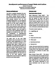
where CT is the coefficient of thrust. By equating the thrust force relation and torque relation, the axial induction factor and the angular induction factor a' can be calculated iteratively. When the iteration converges, the induction factors can be determined and are then used to calculate the angles of attacks and thrust for each blade element separately for the wind turbine performance analysis. Usually wind turbine rotors are designed at specific conditions; however with more and more wind penetration, the optimized design that minimizes the cost of energy becomes mandatory. Several studies have been motivated by this need, focusing on rotor optimization by considering blade chord and twist optimization. Particularly for countries in the MENA region, like Egypt, additional cost benefits can be achieved by considering site specific (wind conditions dictated by the histogram of the specific location under consideration) designs with low surface contamination sensitivity. In this work, we considered Zaafarana site wind conditions for our optimization process and comparison of AEP with different designs. The AEP is calculated according to wind frequency distribution calculated by Weibull distribution [5]: k
v k−1
fw (v) = A (A)
.e
v k A
(−( ) )
(19)
where fw is the frequency of wind velocity v. According to Mortensen et al. [6], Zaafarana site has a Weibull distribution shape factor k=3.19 and
𝐴=
RESD © 2015 http://apc.aast.edu
𝑈𝑚𝑒𝑎𝑛 𝛤(1+1⁄𝑘)
= 10.2 𝑚/𝑠
(20)
108
Journal of Renewable Energy and Sustainable Development (RESD)
This represents a very attractive site for wind farms.
Fig .1. Weibull frequency distribution at k=3.19, A=10.2
The AEP of both NREL and site-specific wind turbine is calculating by using the equations: n−1
AEP = ∑ i=1
(Pvi − Pvi−1 ). (f(vi < v < vi+1 ). 8760 (21)
Umean@Hub Height Umean@Ref. Height
=(
90 24.5
)α
(22)
where Pv is power generated by this wind turbine at wind velocity v, Umean is the mean wind velocity at this site, α (wind shear exponent) = 0.2, Hub height = 90m and Ref. Height=24.5m (anemometer height above ground level). III.
GENETIC ALGORITHM (GA)
In general, optimization techniques fall into one of two main categories: gradient based methods and gradient free methods. Gradient free methods include genetic algorithms (GA), the Nedler-Mead simplex, and particle swarm optimization (PSO). Typical examples of gradient based methods include the conjugate gradient method the method of feasible decent and sequential quadratic programming. One of the modern optimization techniques that are used widely in research, especially in wind turbine rotor optimization, is Genetic Algorithm. Unlike gradient based optimization methods, where objective function has to be continuous and differentiable to be solved, GA is a heuristic optimization method that the search for the optimum solution starts from a random set of solutions. These random solutions are then evaluated and the best solutions are then re-entered to the process several times until an optimum solution
June 2015 - ISSN 2356-8569
is found [7]. In this work, GA was used in the optimization process because it fits the wind turbine parameters optimization process more than other heuristic optimization methods. For example, Simulated Annealing (SA), despite its simplicity and flexibility, is not useful in problems where many local optimum values exist. Another example is the Ant System optimization method that mimics the behavior of ant colony in finding the shortest route to food. Despite the high reliability of this method, it is computationally more demanding than other methods since its generation complexity increases as the generation number increases. More information about heuristic optimization methods can be found in Maringer [7]. To avoid the high time consumption of the GA, the variables chord lengths and twist angles distribution along the blade were generated using Bezier curves with only five control points for each curve to decrease the complexity of the problem and at the same time to ensure smooth distribution of chord lengths and twist angles along the blade. Genetic Algorithm was first invented by Holland [8] in the 1970s to mimic the evolution that happens in nature. This technique is achieved by generating a number of random individuals (called initial population); each consists of randomly chosen string of parameters to be optimized (called genes) and each individual is given a parameter that measures its proximity to the objective of the optimization process. This parameter is called fitness. After that, crossover (or mating) is achieved by splitting each two individuals (called parents) at a random point of the string and exchanging its half with the other to form a new string of genes called offspring or child. The choice of parents from the initial population is achieved by Tournament Selection technique that compares each two randomly chosen individuals. The one which wins this comparison, i.e. has more fitness than the other, is promoted to the mating pool of parents. That is to say, the higher the fitness the higher the chance of the individuals genes to reach the next generations. More details about this technique can be found in Deb [9].
RESD © 2015 http://apc.aast.edu
109
Journal of Renewable Energy and Sustainable Development (RESD)
Fig .2. GA main procedure
The used technique in this work is called Multiple Elitism (ME) Genetic Algorithm presented by Soremekun et al. [10]. The difference between the ME technique and the technique described above is that after each crossover process, all parents and offspring are assembled in one pool and individuals with higher fitness are chosen to ensure fast conversion towards the optimum individual. IV.
DESIGN OF SITE SPECIFIC WIND TURBINE
In this design, the NREL S818, S830 and S831 were used to replace DU-91-W2-250, DU-93-W-210 and NACA-64-618 airfoils respectively in the baseline NREL 5MW wind turbine design. According to Diab et al. [11], the S-Airfoil family showed less deterioration in aerodynamic performance in dusty environments and hence this design will be suitable for MENA region, specially Egypt. In this design, the NREL S818, S830 and S831 were used to replace DU-91-W2-250, DU-93-W-210 and NACA-64-618 airfoils respectively in the baseline NREL 5MW wind turbine design. According to Diab et al. [11], the S-Airfoil family showed less deterioration in aerodynamic performance in dusty environments and hence this design will be suitable for MENA region, specially Egypt. In the new design, the root airfoils (namely DU-99-W-405, DU-99-W-350 and DU-97-W-300) were not changed in the S-airfoil family design for the following reasons:
There are no corresponding airfoils in the S-airfoil family to the root DU-family airfoils (having the same thickness to chord ratio. Root sections with high thickness to chord ratio are used in the wind turbine rotor to withstand bending moment. Hence, it cannot be replaced with other sections with low thickness to chord ratios.
June 2015 - ISSN 2356-8569
According to Rooij and Timmer [12], DU airfoils give the lowest roughness sensitivity for airfoils with thickness to chord ratios between 30% and 40%.
The root section of the wind turbine blade has a little effect on the overall generated power of the rotor. Hence, performance deterioration due to dust accumulation on root airfoils will not have significant effect on generated power.
After selecting the airfoil shapes, the aerodynamic parameters (lift, drag and moment coefficients) are calculated using XFOIL software and hence the design angle of attack was selected to have the max CL/CD value. The twist angle and chord lengths were calculated using Schmitz equations [13]: 2
𝑅
𝛽(𝑟)𝑆𝑐ℎ𝑚𝑖𝑡𝑧 = 3 tan−1 𝑟𝜆 − 𝛼
(23)
1 16𝜋𝑟 1 𝑅 𝑠𝑖𝑛2 (3 𝑡𝑎𝑛−1(𝜆𝑟)) 𝐶𝐿
𝑐(𝑟)𝑆𝑐ℎ𝑚𝑖𝑡𝑧 = 𝐵
(24)
where β(r) is the twist angle at radius r, R is the blade tip radius, λ is the tip speed ratio, α is the design angle of attack of the airfoil section, c(r) is the chord length of the airfoil section at radius r and CL is the design lift coefficient of the airfoil sections.Since the root airfoils in the baseline NREL 5MW wind turbine are already designed for max CL/CD twist angles, these angles are not changed in the S-airfoil family design. The baseline design was simulated at wind velocities ranges from cut-in to cut-out speed, using FAST Modularization Framework [14] to calculate AEP at specified Weibull distribution. V. RESULTS AND DISCUSSIONS The Simulation and optimization process includes simulation of four wind turbine designs:
Case 1: NREL 5MW baseline design (described in [15]).
Case 2: Optimized NREL 5MW wind turbine.
Case 3: Baseline site-specific wind turbine design using the S-Airfoil family.
Case 4: Optimized site specific wind turbine design.
RESD © 2015 http://apc.aast.edu
110
Journal of Renewable Energy and Sustainable Development (RESD)
The baseline design (Case 1) power curve at each wind speed was verified against the power curve provided in the definition report of the NREL 5MW [15]. After that, the AEP was calculated for all cases. After calculation of the AEP of the four cases and running optimization processes of cases 2 and 4 using a MATLAB optimization code coupled to FAST Modularization Framework to run the optimization process, the results were as follow.
Fig .3. Twist angle distribution along the rotor blade for cases 1 to 4
June 2015 - ISSN 2356-8569
optimization for Zaafarana wind distribution. This highlights the importance of tailoring design and optimization of wind turbine aerodynamic parameters on specific wind distribution along the year and attracts attention towards the need of designing and manufacturing special wind turbines that serve in specific sites to increase the ability of energy extraction from wind. On the other hand, for S-airfoil wind turbine rotor, the AEP is less than the optimized Baseline design. This is a result of replacing DU airfoils with NREL airfoils because DU airfoils have better aerodynamic characteristics than NREL airfoils. However, the NREL airfoil family is still recommended for Zaafarana wind farm since it is less surface contamination sensitive, according to Diab et al. [11]. According to roughness sensitivity data found in [11,12 and 16], the new aerodynamic performance of the rough airfoils of DU-91-W2-250, DU-97-W-300, S818, S830 and S831 were used to calculate the AEP of optimized wind turbine after dust accumulation, while the other airfoils were assumed to maintain the same aerodynamic performance as clean airfoils due. The optimized NREL 5MW wind turbine shows a drop in AEP form 34.83 to 29.75 GWh (-14.6% in AEP), while the S-airfoil family design shows a drop in AEP form 32.571 to 32.497 GWh due to dust accumulation on the blade surface. Hence, the loss in AEP along the year due to using NREL S-airfoil family airfoils will decrease the loss in AEP due to deterioration of aerodynamic characteristics of the DU and NACA airfoil sections in the baseline NREL 5MW rotor. V. CONCLUSION
Fig .4. Chord length distribution along the rotor blade for cases 1 to 4 Table 1. AEP OF CASES 1 TO 4
Case No.
AEP (GWh)
Improvement from Baseline case (%)
Improvement from Case 1 (%)
1
32.88
-
-
2
34.83
5.9
5.9
3
32.18
-
-2.13
4
32.57
1.2
-0.94
The previous results show that a 5.9% improvement can be achieved on a baseline design after
From the previously mentioned results, we can conclude that the new S-airfoil design and optimization resulted in a new design that is suitable for Saharan areas (like areas found in Egypt and many countries in the MENA region) with higher AEP than the baseline design. This work also concludes that design and optimization of site-specific wind turbine design play a very important role in increasing the wind turbine’s AEP and hence decreasing the cost of energy generated from the wind turbine. Such techniques along with consideration of the conditions in which the turbine operates, such as dust, must be taken into consideration during the process of design or selection of wind turbines to be installed in a specific wind farm.
RESD © 2015 http://apc.aast.edu
111
Journal of Renewable Energy and Sustainable Development (RESD)
June 2015 - ISSN 2356-8569
REFERENCES [1]
[2]
[3]
[4]
Maheri, A., Noroozi, S. and. Vinney, J. “Application of combined analytical/FEA coupled aero-structure simulation in design of wind turbine adaptive blades”. Renewable Energy. Volume 32. Issue 12, October 2007. Pages: 2011-2018. Xiong, L., Yan, C. and Zhiquan, Y. “Optimization model for rotor blades of horizontal axis wind turbines”. Frontiers of Mechanical Engineering in China. Pages: 483488.
Mohamed, M. and Wetzel, K.. “3D Woven Carbon/Glass Hybrid Spar Cap for Wind Turbine Rotor Blade”. Tran. of ASME. Journal of Solar Energy Engineering. Issue 128 (2006). Pages:562-573. Hansen, M. Aerodynamics of Wind Turbines, 2nd ed. London: Earthscan. 2008.
[6]
Mortensen, N., et al. “Wind atlas for Egypt: measurements, microand mesoscale modellin”. European Wind Energy Conference EWEC 2006. 2006.
[8]
Deb, K. Multi-objective optimization using evolutionary algorithms. John Wiley and Sons Ltd. 2001.
[10] Soremekun, G., Gürdal, Z., Haftka, R.and Watson, L. “Composite laminate design optimization by genetic algorithm with generalized elitist selection”. Computers & Structures. Volume 79. Issue 2. January 2001. Pages: 131-143. [11]
Diab, A., Alaa, M., Hossam El-Din, A. , Salem, H.and Ghoniem, Z. “Performance Degradation of Wind Turbine Airfoils Dust Contamination: A Comparative Numerical Study”. ASME Turbo Expo. 2015 (2015).
[12]
Rooij, R. and Timmer, W. "Roughness Sensitivity Considerations for Thick Rotor Blade Airfoils." Journal of Solar Energy Engineering 125.4 (2003). 468. Web.
[13]
Gasch, R. and Twele J. “Wind Power Plants: Fundamentals, Design, Construction and Operation”. Berlin: Springer Berlin. 2011.
[14]
Jonkman, J. and, Buhl, M. “FAST user’s guide”. Tech. Rep. Golden, Colorado: National Renewable Energy Laboratory. 2005.
[15]
Jonkman, J. , Butterfield, S., Musial, W. and Scott, G. “Definition of a 5MW Reference Wind Turbine for Offshore System Development” (2009)
[16]
Buhl, M. "Wind Turbine Airfoil List.". Wind Turbine Airfoil List. NWTC. 6 July 2012. Web. 02 May 2015.
Xudong, W., Jin, Ch., ZhongShen, W., Jun Zhu, and NørkærSørensen, J. “Shape optimization of wind turbine blades” . Wind Energy. Pages: 781-803.
[5]
[7]
[9]
Maringer, D. “Portfolio Management with Heuristic Optimization”. Dordrecht: Springer, 2005. Holland, J. Adaptation in natural and articial systems. Ann Arbor, MI: The University of Michigan Press. 1975.Ann Arbor, MI: The University of Michigan Press. 1975.
RESD © 2015 http://apc.aast.edu
112