Hindawi Mathematical Problems in Engineering Volume 2018, Article ID 3084184, 9 pages https://doi.org/10.1155/2018/3084184
Research Article Optimizational Mathematical Modeling Methods of DC Traction Power Supply System for Urban Mass Transit Jing Shang , Jie Zhang
, and Zhixue Zhang
CRRC Zhuzhou Institute Co., Ltd., Zhuzhou, Hunan 412001, China Correspondence should be addressed to Jie Zhang;
[email protected] Received 21 September 2018; Accepted 28 November 2018; Published 16 December 2018 Academic Editor: Honglei Xu Copyright © 2018 Jing Shang et al. This is an open access article distributed under the Creative Commons Attribution License, which permits unrestricted use, distribution, and reproduction in any medium, provided the original work is properly cited. Time-varying characteristics of DC traction power supply system network structure are the key technical problem in its mathematical modeling. Based on node admittance network equation theory, this paper puts forward an optimizational mathematical modeling method of DC traction power supply system for urban mass transit, and that is to conduct automatic sequencing firstly for all the nodes on both ends of traction substation and the train according to the given rules, then arrange the nodes according to the position coordinates and save them into the arrays, and finally generate the node admittance network equation of DC traction power supply system according to the self-adaptive real-time dynamics of node arrays and input parameter documents. Simulation study indicates the rationality and correctness of optimizational mathematical modeling method of DC traction power supply system for urban mass transit.
1. Introduction With the rapid development of Chinese economy and the growth of the urban traffic, urban mass transit, as a kind of means of transport with a lot of advantages, such as high speed, safety, reliability, punctuality, comfort, convenience, and pollution-free technology, has been increasingly used in China [1–3]. Urban mass transit power supply system is an important part of urban railway transportation. It is the source of urban mass transit operations, which takes charge of the supply and transmission of electric energy. It provides tractive power supply for electric train and dynamic lighting power supply for the station, section, rolling stock depot, control center, and other buildings. Urban mass transit power supply system should meet the basic requirements such as safety, reliability, applicability, economy, and advancement. Therefore, a reasonable design of urban mass transit power supply system is very essential [4, 5]. DC traction power supply system mathematical modeling plays an extremely important role in the design of urban mass transit power supply system, which is really necessary for design of power supply system. It relates to the critical
factors [6, 7] of system design, such as power supply system composition, tractive power supply mode, settings of the traction substation, and capacity of traction rectifier unit. The particularity of urban mass transit lies in the persistent moving of many trains. Many trains, the traction substation, the overhead lines, the steel rails, and the ground constitute the changing DC power grid structure at different time. In terms of theory of circuit, DC traction power supply system is a complicated time-varying network. Thus it causes problems [8, 9] to the mathematical modeling of DC traction network with a fixed circuit diagram. In addition, the quantities or the locations of traction substations of different urban mass transit line are usually not the same, so the DC tractive power supply network topology structures are also different. The existing mathematical modeling methods for DC traction power supply are the average traffic volume method and the method of sections of train working diagram. The average traffic volume method can calculate the average voltage, current of the DC traction power supply, but it cannot get the instant electrical character. The method of sections of train working diagram usually takes the train or traction substation as the break point and
2 calculate based on the whole traction network divided into a number of independent power supply sections. Actually, the traffic flow or power of urban railway train comes from all the traction substations [10, 11] across the whole line connected to the traction network. So the calculation precision of method of sections of train working diagram is low [12, 13]. The above mathematical modeling methods of DC traction power supply system cannot adapt to the quantities of traction substations and the change of position of different lines [14, 15]. On account of the above technical problems, a kind of adaptive real-time dynamic mathematical modeling method for DC traction power supply system of urban mass transit is put forward on this basis and leads to a patent [16]. This method regards DC traction power supply system of the whole line as a complete real-time dynamic change system. And it is assumed that the traffic flow or power of the train is distributed between the traction substations interlinked by the traction networks, so the calculation precision of method can be ensured. It can calculate the voltage, current, or power of the whole line’s traction substation or trains of DC traction power supply system. The real-time dynamic mathematical model for DC traction power supply system can be self-adaptive generated with arbitrary input number and location of traction substations. It also can be self-adaptive generated with real-time change of the number and position of the locomotives.
2. Optimizational Mathematical Modeling of DC Traction Power Supply System First of all, this section introduces the principle of selfadaptive real-time dynamic mathematical modeling method for DC traction power supply system of urban mass transit, and a simple example is used for specific explanations on this method after introducing the principle in order to make the method more understandable. 2.1. Principles of Optimizational Mathematical Modeling of DC Traction Power Supply System. Before establishing an optimizational dynamic mathematical model of DC traction power supply system for urban mass transit, the following basic assumptions shall be made on the premise of meeting the precision requirements for engineering calculation: (a) It is assumed that the AC voltage of each traction substation across the whole line is the same and stable, without regard to the effect of AC system changes on calculation. (b) It is assumed that all the traction substation transformers and rectifiers of the whole line are considered as the voltage source branch with internal resistance. (c) It is assumed that the traction network system is of a uniform and symmetrical structure. The traction network system has a consistent resistance per unit length. (d) The coordinates of feeding point of traction network are deemed to be the coordinates of location of traction substation, and it is believed that the feeding point and backflow point of traction network are at the same coordinate position.
Mathematical Problems in Engineering (e) The locomotive will be regarded as a power source. The power of the locomotive at a certain position at a time shall be given according to the result of traction calculation. (f) The start station position coordinate shall be regarded as the zero point and will serve a reference for calculation of the upward or downward running position coordinates. The basic idea of the real-time dynamic mathematical modeling method of DC traction power supply system for urban mass transit presented in this paper is as follows. Firstly, input the parameters files at t moment. It is set that the serial numbers of the nodes on both ends of the traction substation and the node on both ends of the locomotive are continuous. Sequence the nodes on both ends of the traction substation, check if the position of each locomotive overlaps with the location of traction substation at t moment, and then sequence the nodes on both ends of the locomotive. Arrange the upward contact line system, upward rail, downward contact line system, and downward rail node number, respectively, according to the location coordinates in an increasing sequence, and save them into the corresponding arrays, respectively. The equivalent circuit diagram of DC traction power supply system can be generated automatically in line with the node array. According to the parameters such as the equivalent voltage source amplitude of traction substation, the value of internal resistance, the power of locomotive, the line resistance between two nodes, and the leakage conductance of rail, based on the modeling principle of node admittance network equation, the node admittance network equation at t moment will be generated automatically with the stored four node arrays and the input parameters. For the next moment (t + Δ𝑡), the parameter files at t + Δ𝑡 moment shall be read in, and then the dynamic mathematical model of DC traction power supply system will be regenerated, the method of which is the same as above. Along with the change of time and constant repetition, the real-time dynamic mathematical modeling of DC traction power supply system for urban mass transit will be achieved. The specific real-time dynamic mathematical modeling methods are as follows: (a) Input Parameter Files at t Moment. Set the input parameters as follows: the quantity of traction substation is n and the locations are 𝐿 1 , 𝐿 2 ⋅ ⋅ ⋅ 𝐿 𝑛 , respectively; the quantity of upward locomotive at T moment is m given by traction calculation, the positions are upward 𝐿 𝑚1 , 𝐿 𝑚2 ⋅ ⋅ ⋅ 𝐿 𝑚𝑚 , respectively, and the corresponding powers are 𝑝𝑚1 , 𝑝𝑚2 ⋅ ⋅ ⋅ 𝑝𝑚𝑚 , respectively; the quantity of downward locomotive is k, the positions are downward 𝐿 𝑘1 , 𝐿 𝑘2 ⋅ ⋅ ⋅ 𝐿 𝑘𝑘 , respectively, and the corresponding powers are 𝑝𝑘1 , 𝑝𝑘2 ⋅ ⋅ ⋅ 𝑝𝑘𝑘 , respectively. (b) Sequencing of Nodes at Both Ends of Traction Substation. Suppose the serial number of nodes on both ends of the traction substation is continuous. Because the quantity of traction substation is n, the nodes on both ends of the traction substation are sequenced according to the position of traction substation in an increasing sequence, that is, 1, 2, 3, 4, ⋅ ⋅ ⋅ 2𝑛 − 1, 2𝑛, for the advantage of programming.
Mathematical Problems in Engineering
3 2n + 1
1
3
2n − 3
2n + 2m − 1
2n − 1 T_up
train station
2n + 2
2n + 2m 4
2
2n
2n − 2
2n+2m+1 2n+2m+2k−1
2n+2m+2
2n+2m+2k
R_up
T_down
R_down
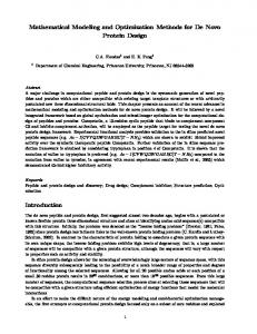
Figure 1: Equivalent circuit diagram of DC traction power supply system.
(c) Sequencing of the Locomotive Node on Both Ends. Check if the locomotive position overlaps with the traction substation location according to (1). 𝑠𝑖 − 𝑠𝑗 < 𝜉 (1) where 𝑠𝑖 is the position of the locomotive, 𝑠𝑗 is the location of traction substation, and 𝜉 is a set positive number. When the conditions of (1) are met, if a locomotive position overlaps with a traction substation location, the nodes of the locomotive shall not be numbered, and the node current of traction substation is the superposition of traction substation current and locomotive current. When the conditions of (1) cannot be met, if the locomotive position does not overlap with the traction substation location, a new node number of locomotives will be increased. The nodes on both ends of the locomotive will be sequenced according to the quantity of upward and downward running locomotives at t moment and based on the locomotive position in an increasing sequence. Set the quantity of upward locomotives as m, and the node numbers of upward locomotives are as follows: 2𝑛 + 1, 2𝑛 + 2, 2𝑛 + 3, 2𝑛 + 4, ⋅ ⋅ ⋅ 2𝑛 + 2𝑚 − 1, 2𝑛 + 2𝑚. Set the quantity of downward locomotives as k, and the node number of downward locomotives are as follows: 2𝑛 + 2𝑚 + 1, 2𝑛 + 2𝑚 + 2, 2𝑛 + 2𝑚 + 3, 2𝑛 + 2𝑚 + 4, ⋅ ⋅ ⋅ 2𝑛 + 2𝑚 + 2𝑘 − 1, 2𝑛 + 2𝑚 + 2𝑘. The node numbers of upward locomotives are 2𝑛 + 1, 2𝑛 + 2, 2𝑛 + 3, 2𝑛 + 4, ⋅ ⋅ ⋅ 2𝑛 + 2𝑚 − 1, 2𝑛 + 2𝑚. The node numbers of downward locomotives are 2𝑛 + 2𝑚 + 1, 2𝑛 + 2𝑚 + 2, 2𝑛 + 2𝑚 + 3, 2𝑛 + 2𝑚 + 4, ⋅ ⋅ ⋅ 2𝑛 + 2𝑚 + 2𝑘 − 1, 2𝑛 + 2𝑚 + 2𝑘. (d) Save the Nodes into the Array. Set T up as upward contact line system, R up as upward rail, T down as downward contact line system, and R down as downward rail. Arrange the upward contact line system, upward rail, downward contact line system, and downward rail node numbers, respectively, according to the location coordinates in an increasing sequence, and save them into the corresponding array respectively.
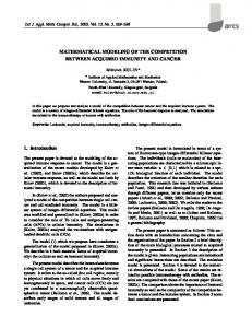
(e) Automatic Generation of the Equivalent Circuit of DC Traction Power Supply System. According to the node array, the equivalent circuit of DC traction power supply system can be generated automatically, as shown in Figure 1. (f) The Node Admittance Matrix Automatically Generated Based on the Position Arrangement, Types, and Traction Network Line Parameters of the Node Array Elements in the Array. The node admittance matrix order 2 × (𝑛 + 𝑚 + 𝑘) depends on the number of nodes. Set the initial value of all the elements of the node admittance matrix as 0, calculate the value of each matrix element, and then add them to the corresponding position of node admittance matrix, and eventually form a complete node admittance matrix. A Calculation of Mutual Admittance between the Nodes. (1) Calculation of line admittance: calculate the admittance between two adjacent array elements of the above four arrays, respectively, according to the node position coordinates and resistance value per unit length of the contact line and rail. (2) Calculation of mutual admittance of the nodes on both ends of the traction substation and that of the locomotive: calculate the mutual admittance of numerical value elements at the same arrangement position in T up, R up, T down, and R down arrays, respectively. The mutual admittance of the nodes at both ends of traction substation is determined by the internal resistance of traction substation. Set the mutual admittance of the nodes on both ends of locomotive as 0. B Calculation of the Self-Admittance of Nodes. As the rail is not completely insulated, part of traction current will leak into the ground and flow back to the rail and return to the traction substation. Therefore, at the time of modeling of rail, the leakage resistance from the rail to the earth shall be considered. According to the uniform transmission line
4
Mathematical Problems in Engineering ZL
YL /2
YL /2
Figure 2: Type ∏ equivalent circuit of the rail.
theory, a length of rail can be equivalent to type ∏ equivalent circuit, as shown in Figure 2. The leakage conductance from the rail node to the ground can be calculated by Figure 1 according to the length of the rail and the leakage resistance from the rail per unit length to the ground. (g) Calculate the Self-Admittance of the Contact Line System Node and Rail Node Respectively. (1) Calculation of selfadmittance of the nodes of upward and downward traction networks: the self-admittance of the node of upward traction network is equal to the negated value of the sum of the mutual admittance of this node and the adjacent node in the same array and that of this node and the node at the same arranged position of another upward array. The calculation method of the self-admittance of the node of downward traction network is the same as that of the upward one. (2) Calculation of self-admittance of the nodes of upward and downward rails: the self-admittance of the node of upward rail is equal to the negated value of the sum of the mutual admittance of this node and the adjacent node in the same array and that of this node and the node at the same arranged position of another upward array plus the leakage conductance value from this node to the ground. The calculation method of the self-admittance of the node of downward rail is the same as that of the upward one. According to the calculation above, it is able to get all the element values of matrix admittance, which can generate the corresponding node admittance matrix 𝑌 automatically. (h) The Node Current Column Vector Generated Automatically Based on the Node Array Element Number, Type, and the Equivalent Current Source Parameters. The node current column vectors are row 2 × (𝑛 + 𝑚 + 𝑘) and column 1. The initial element value is 0. Arrange the node current vector according to the node number in an increasing sequence. The traction substation and locomotive are equivalent current sources. Firstly, it is assumed that the current of traction substation and that of locomotive are of the positive direction. Set the injected current of node as negative, and the outflow current of node as positive. The absolute value of node current of traction substation is 𝑈𝑠𝑗 /𝑅𝑠𝑗 . 𝑈𝑠𝑗 and 𝑅𝑠𝑗 are the equivalent voltage source amplitude and internal resistance of traction substation, respectively. The absolute value of node current of the locomotive is 𝑃𝑠𝑖 /𝑈𝑠𝑖 . 𝑃𝑠𝑖 and 𝑈𝑠𝑖 are the power and terminal voltage of the locomotive, respectively. Firstly, determine the node type. It is the node of traction substation or that of locomotive. Calculate the node current vector by the
corresponding formula according to the type of nodes and the parameters of the equivalent current source. According to the above calculation, it is able to get all the element values of node current column vector, which can generate the corresponding node current column vector 𝐼 automatically. (i) Automatic Generation of Mathematical Model of DC Traction Power Supply System. At this point, the mathematical model 𝑌𝑈 = 𝐼 of DC traction power supply system at t moment can be generated automatically. (j) The Mathematical Model of DC Traction Power Supply System at the Next Moment Generated Automatically. The above calculation is a mathematical model deduction at a certain moment since the DC traction power supply system is a real-time dynamic network. For the mathematical model at the next t + Δ𝑡 moment, first of all, input the file according to the parameters at t + Δ𝑡 moment, determine the number and position of trains at the new moment and their corresponding power and get to know the DC traction network structure and loading conditions at the new moment accordingly to establish the mathematical model for DC traction power supply system at the new moment with the same mathematical modeling method as above. Repeat constantly as time changes. Summing up the above calculation steps, the flow chart of self-adaptive real-time dynamic mathematical modeling method of DC traction power supply system for urban mass transit is as in Figure 3. 2.2. Example of Optimizational Mathematical Modeling Method of DC Traction Power Supply System for Urban Mass Transit. The following is a simple example to illustrate the method of automatically generated mathematical model of DC traction power supply system at t moment: Set the number of traction substation input in DC traction power supply system as N = 2, and the positions are 0 km and 30 km, respectively. The quantity of upward locomotives at t moment given by traction calculation is 2, the positions are upward 10 km and 20 km, respectively, and the corresponding locomotive powers are p1 and p2, respectively. The quantity of downward locomotives is 3, the positions are downward 10 km, 20 km, and 25 km, respectively, and the corresponding locomotive powers are p3, p4, and p5, respectively. Firstly, sequence the nodes on both ends of the traction substation, and set the node numbers of traction substation at 0 km and 30 km as 1, 2, 3, and 4, respectively. Check if the locomotive overlaps with the traction substation, and then number the nodes at both ends of locomotives at upward 10 km and 20 km, respectively, according to 5, 6, 7, and 8; and number the nodes of locomotives at downward 10 km, 20 km, and 25 km, respectively, according to 9, 10, 11, 12, 13, and 14. Arrange the upward contact line system, upward rail, downward contact line system, and downward rail node numbers, respectively, according to the position coordinates in an increasing sequence, and save them in the corresponding arrays, then we get
Mathematical Problems in Engineering
Quantity, position and corresponding power of upward and downward locomotive at sampling moment given by traction calculation
parameters
5
Generating data files
Read in data file at t moment
Parameters of rectification traction substation Parameters of DC traction network line
Sequencing of nodes on both ends of traction substation
Sequencing of nodes on both ends of locomotive
Nodes saved in array
Automatic generation of equivalent circuit diagram of DC traction power supply system
Automatic generation of node admittance matrix by node array elements based on the position arrangement, type and traction network line parameters
Automatic generation of node current column vector based on node array element number, type and equivalent current source parameters
Automatic generation of mathematical model of DC traction power supply system
Solve the mathematical model and output the calculation results
Figure 3: Flow chart of optimizational mathematical modeling method of DC traction power supply system for urban mass transit.
T up : [1, 5, 7, 3] R up : [2, 6, 8, 4] T down : [1, 9, 11, 13, 3]
(2)
R down : [2, 10, 12, 14, 4] . So the equivalent circuit for dc traction power supply system at t moment is available (see Figure 4). (I) Automatic Generation of Node Admittance Matrix
A Mutual Admittance between Computational Nodes. (1) Calculation of the line admittance: according to the node position coordinates, the contact line, resistance value per unit length of rail shall be calculated for the admittance between two adjacent array elements of four node arrays respectively. (2) Calculation of mutual admittance of the nodes on both ends of the traction substation and that of the locomotive: calculate the mutual admittance of numerical value at the same arrangement position in T up, R up, T down, and
6
Mathematical Problems in Engineering Table 1: The main parameters of Guangzhou Metro Line 4.
Name Number of pulses Capacity of rectifier unit Ration of rectifier transformer Through impedance of rectifier transformer Half-through impedance of rectifier transformer Rated voltage of DC traction power supply system Length of line The resistance per unit length of contact line system Resistance per unit length of rail Leakage resistance from the rail to the ground Total weight of the train Maximum running speed of train Train tracking interval at recent rush hour
5
1
T_up
train
station 2
3
7
Value 24 2 x 2200 kVA 33 kV/1180 V 8% 6.5% 1500 V 46.3 km 0.0143Ω/km 0.0137Ω/km 15Ω∙km 175t 90 km/h 450 s
6
8
4
9
11
13
10
12
14
R_up
T_down
R_down
Figure 4: Equivalent circuit of DC traction power supply system at t moment.
R down arrays. The mutual admittance of the nodes on both ends of traction substation depends on the internal resistance of traction substation. Set the mutual admittance of the nodes at both ends of locomotive as 0. B Self-Admittance of Computational Nodes. Self-admittance of node of contact line system: if 𝑌(1, 1)𝑢𝑝 = −𝑌(1, 2)𝑢𝑝 − 𝑌(1, 5)𝑢𝑝, 𝑌(1, 1)𝑑𝑜𝑤𝑛 = −𝑌(1, 2)𝑑𝑜𝑤𝑛 − 𝑌(1, 9)𝑑𝑜𝑤𝑛, and then 𝑌(5, 5)𝑢𝑝 = −𝑌(5, 1)𝑢𝑝 − 𝑌(5, 7)𝑢𝑝 − 𝑌(5, 6)𝑢𝑝. When calculating the self-admittance of the positive node of traction substation, 𝑌(1, 1) = 𝑌(1, 1)𝑢𝑝 + 𝑌(1, 1)𝑑𝑜𝑤𝑛 + 𝑌(1, 2). Self-admittance of the rail node: if 𝑌(6, 6)𝑢𝑝 = −𝑌(6, 2)𝑢𝑝 − 𝑌(6, 5)𝑢𝑝 + 𝑔6, 𝑔6 is the leakage admittance from node 6 of rail to the ground. When calculating the
self-admittance of negative node of traction substation, if 𝑌(2, 2) = 𝑌(2, 2)𝑢𝑝 + 𝑌(2, 2)𝑑𝑜𝑤𝑛 + 𝑌(1, 2) − 𝑔2, 𝑔2 is the leakage admittance from the negative node 2 of traction substation to the ground. According to the above calculation, it is able to get all the element values of matrix admittance, which can generate the corresponding node admittance matrix automatically. (II) Automatic Generation of Node Current Column Vector. If the currents of nodes 1 and 2 of traction substation at 0 km are −𝑈𝑠1 /𝑅𝑠1 and 𝑈𝑠1 /𝑅𝑠1 , respectively, the currents of nodes 5 and 6 of locomotive at upward 10 km are 𝑃1 /𝑈𝑡𝑟𝑎𝑖𝑛1 and −𝑃1 /𝑈𝑡𝑟𝑎𝑖𝑛1 , respectively. According to the above calculation, it is able to get all the element values of node current column vector, which can generate the corresponding node current column vector 𝐼 automatically. At this point, the node admittance network equation 𝑌𝑈 = 𝐼 of DC traction network under normal operation conditions at t moment can be generated automatically.
3. Test Valuation In order to verify the correctness of self-adaptive real-time dynamic mathematical modeling method of DC traction power supply system for urban mass transit presented in this article, a simulation analysis is made for power supply conditions of the section from the Olympic Center to Chongwei of Guangzhou Metro Line 4 and compared with the results tested in actual use. The setting scheme of Guangzhou Metro Line 4 traction substation from Chebei South Station to Huangge North Station of Line 4 is Chebei, Wanshengwei, Guanzhou, Nanting, Xinzao, Xinguan Section, Guanqiao, Shihui, Haibang, Diyong, Dongyong, Qingsheng, Huangge North, and Jiaomen, 14 stations in total [13]. The main parameters of Guangzhou Metro Line 4 are shown in Table 1. The position and power distribution of the train at a certain moment are as shown in Table 2 [13].
Mathematical Problems in Engineering
7
Table 2: Position and power distribution of the metro at a certain moment. Upward train Power (kW) Position (km) 200 1.349 1764 5.178 672 10.291 200 13.853 779 20.125 1746 25.367 1439 29.047 200 34.229 2127 39.783 200 — Voltage (Unit:V)
Position (km) 0 3.513 7.34 12.394 17.53 21.616 26.715 33.012 35.833 43.570
Power (kW) 200 200 1577 321 825 976 200 534 1978 —
Downward train Power (kW) Position (km) 200 3.146 200 6.796 200 12.293 1743 17.477 245 21.567 1252 26.707 1953 32.822 780 35.694 200 41.081 1736 46.059
Position (km) 0.966 5.176 10.279 13.524 20.172 25.154 28.871 34.108 39.607 43.383
Power (kW) 200 200 2191 277 762 200 1960 200 200 200
Voltage of upward contact line system across the whole line
1580 1570 1560 1550 1540 1530 0
5
10
15
20 25 30 Distance (Unit:km)
35
40
45
40
45
40
45
40
45
Voltage (Unit:V)
Upward contact line system Train Traction substation 15 10 5 0 −5 −10
Voltage of upward rail across the whole line
0
5
10
15
20 25 Distance (Unit:km)
30
35
Voltage (Unit:V)
Upward rail Traction substation Voltage of downward contact line system across the whole line
1580 1570 1560 1550 1540 1530 0
5
10
15
20 25 Distance (Unit:km)
30
35
Voltage (Unit:V)
Downward contact line system Train Traction substation 15 10 5 0 −5 −10
Voltage of downward rail across the whole line
0
5
10
15
20 25 Distance (Unit:km)
30
35
Downward rail Traction substation
Figure 5: Simulation waveform of DC traction power supply system of the section from Olympic Center to Chongwei of Guangzhou Metro Line 4.
Mathematical Problems in Engineering
Voltage (Unit: V)
8 1580 1575 1570 1565 1560 1555 1550 1545 1540 1535 1530
Voltage of upward contact line system across the whole line
0
4.6
9.3
13.9
18.5
23.1 27.8 Distance (Unit: km)
32.4
37
41.7
46.3
37
41.7
46.3
37
41.7
46.3
37
41.7
46.3
Upward contact line system Train
Voltage (Unit: V)
Rectifier unit
15 12.5 10 7.5 5 2.5 0 −2.5 −5 −7.5 −10
Voltage of upward rail across the whole line
0
4.6
9.3
13.9
18.5
23.1 27.8 Distance (Unit: km)
32.4
Upward rail
Voltage (Unit: V)
Rectifier unit
1580 1575 1570 1565 1560 1555 1550 1545 1540 1535 1530
Voltage of downward contact line system across the whole line
0
4.6
9.3
13.9
18.5
23.1 27.8 Distance (Unit: km)
32.4
Downward contact line system Train Rectifier unit
Voltage (Unit: V)
Voltage of downward rail across the whole line 15 12.5 10 7.5 5 2.5 0 −2.5 −5 −7.5 −10
0
4.6
9.3
13.9
18.5
23.1
27.8
32.4
Distance (Unit: km)
Downward rail Rectifier unit
Figure 6: Waveform of DC traction power supply system of the section from Olympic Center to Chongwei of Guangzhou Metro Line 4 tested in actual.
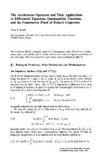
After calculation of upward and downward contact line system and rail voltage distribution across the Guangzhou Metro Line 4 based on the DC traction power supply system structure, parameters, the position and power distribution of the train, and comparison with the data tested in actual, the results are as in Figures 5 and 6.
From up to down of Figure 5 or Figure 6, these curves are upward contact line system voltage, upward rail voltage, downward contact line system voltage, and downward rail voltage. We can see, by comparing Figure 6 with Figure 5, the simulation waveform of upward and downward contact line system and rail voltage distribution across the section
Mathematical Problems in Engineering from Olympic Center to Chongwei of Guangzhou Metro Line 4 achieves high conformity (the max error is 10%) with the waveform provided by the authoritative literature; thus, the correctness of the self-adaptive real-time dynamic mathematical modeling method of DC traction power supply system for urban mass transit presented in this paper is well proven.
4. Conclusion The self-adaptive real-time dynamic mathematical modeling method of DC traction power supply system for urban rail presented in this paper mainly includes four parts: the regular sequences of the nodes on both ends of the traction substation and that of the locomotive; arrangement of the nodes according to location coordinates and storage in the arrays; automatic generation of equivalent circuit diagram of DC traction power supply system based on the node arrays; automatic generation of node admittance network equation of DC traction power supply system with self-adaption based on the equivalent circuit diagram and according to the node arrays and input parameter files. The self-adaptive real-time dynamic mathematical modeling method assumes that the traffic flow or power of the train is distributed between the traction substations integrated by the traction network, which makes the mathematical model more in line with the actual circumstances of the DC traction power supply system for urban mass transit. The self-adaptive real-time dynamic mathematical modeling method can calculate the voltage, current, or power of the whole line’s traction substation or trains of DC traction power supply system. This paper solves the key technical modeling problem caused by DC traction power supply system network structure time-varying characteristics, so that the mathematical model of DC traction power supply system can be generated adaptively and dynamically in real time under the circumstances that the quantities and locations of traction substation are input arbitrarily and the quantities and positions of locomotive change over time. The algorithm has high adaptive ability, which offers a powerful tooling support for design and research of DC traction system for urban mass transit.
Data Availability The data used to support the findings of this study are available from the corresponding author upon request.
Conflicts of Interest The authors declare that they have no conflicts of interest.
Acknowledgments This paper is sponsored by National Key R&D Program of China (2017YFB1200800).
9
References [1] Y. He, K. Huang, and T. Wang, “Overview of traction power supply system for rail transportation,” Journal of Railway Science and Engineering, vol. 2, no. 4, pp. 32–39, 2016. [2] C. S. Chen, H. J. Chuang, and H. M. Shiau, “Stochastic harmonic analysis of mass rapid transit power systems with uncontrolled rectifiers,” IEE Proceedings Communications, vol. 150, no. 2, pp. 224–232, 2003. [3] R. Na, H. Song, and P. Xiaojun, “Research on modeling and simulation of rail transit traction power supply system based on PSCAD,” Guizhou Electric Power Technology, vol. 6, no. 14, pp. 25–30, 2014. [4] S. Hongxi, “Study on DC Main Wiring Scheme of Traction Power Supply System Substation for Transit,” Modern Urban Transit, vol. 2, no. 3, pp. 15–19, 2016. [5] Y. Songwei and Y. Xingshan, Design Principle and Application of Power Supply System for Urban Mass Transit, Southwest Jiaotong University Press, Chengdu, China, 2008. [6] L. Qunzhan and H. Jianmin, Analysis on Tractive Power Supply System, Southwest Jiaotong University Press, Chengdum, China, 2007. [7] W. Xifan, Analysis on Modern Power System, Science Press, Beijing, China, 2003. [8] W. Xiaodong and Z. Hongbin, “Simulation Study on DC Traction Power Supply System for Urban Mass Transit,” Journal of System Simulation, vol. 14, no. 12, pp. 1692–1697, 2002. [9] L. Haidong, H. Tianjian, Y. Zhenzhou et al., “Study on Simulation System of DC Traction Power for Urban Mass Transit,” Journal of System Simulation, vol. 16, no. 9, pp. 1944–1947, 1944. [10] L. Wei, Simulation of Power Supply System for Urban Mass Transit. Masters thesis [Master, thesis], Southwest Jiaotong University, 2006. [11] L. Hui, X. Jiong, and P. Daogang, “Study on dynamic operation simulation of urban mass transit traction power supply system,” Electrical Measurement & Instrumentation, vol. 11, no. 3, pp. 23– 28, 2016. [12] L. Wei, Operational Process Optimization of Trains for Urban Mass Transit and Dynamic Simulation of Tractive Power Supply System. Doctoral thesis [Doctoral, thesis], Southwest Jiaotong University, 2009. [13] Z. Yang, H. Xia, B. Wang, and F. Lin, “An overview on braking energy regeneration technologies in Chinese urban railway transportation,” in Proceedings of the 7th International Power Electronics Conference, IPEC-Hiroshima - ECCE Asia 2014, pp. 2133–2139, Japan, May 2014. [14] A. Gonz´alez-Gil, R. Palacin, and P. Batty, “Sustainable urban rail systems: Strategies and technologies for optimal management of regenerative braking energy,” Energy Conversion and Management, vol. 75, pp. 374–388, 2013. [15] A. Okui, S. Hase, H. Shigeeda, T. Konishi, and T. Yoshi, “Application of energy storage system for railway transportation in Japan,” in Proceedings of the 2010 International Power Electronics Conference - ECCE Asia -, IPEC 2010, pp. 3117–3123, Japan, June 2010. [16] J. Zhang, W. Jian, C. Huaguo et al., “Self-adaptive Real-time Dynamic Mathematical Modeling Methods of DC Traction Power Supply System for Urban Mass Transit: P. R. China,” 2014.
Advances in
Operations Research Hindawi www.hindawi.com
Volume 2018
Advances in
Decision Sciences Hindawi www.hindawi.com
Volume 2018
Journal of
Applied Mathematics Hindawi www.hindawi.com
Volume 2018
The Scientific World Journal Hindawi Publishing Corporation http://www.hindawi.com www.hindawi.com
Volume 2018 2013
Journal of
Probability and Statistics Hindawi www.hindawi.com
Volume 2018
International Journal of Mathematics and Mathematical Sciences
Journal of
Optimization Hindawi www.hindawi.com
Hindawi www.hindawi.com
Volume 2018
Volume 2018
Submit your manuscripts at www.hindawi.com International Journal of
Engineering Mathematics Hindawi www.hindawi.com
International Journal of
Analysis
Journal of
Complex Analysis Hindawi www.hindawi.com
Volume 2018
International Journal of
Stochastic Analysis Hindawi www.hindawi.com
Hindawi www.hindawi.com
Volume 2018
Volume 2018
Advances in
Numerical Analysis Hindawi www.hindawi.com
Volume 2018
Journal of
Hindawi www.hindawi.com
Volume 2018
Journal of
Mathematics Hindawi www.hindawi.com
Mathematical Problems in Engineering
Function Spaces Volume 2018
Hindawi www.hindawi.com
Volume 2018
International Journal of
Differential Equations Hindawi www.hindawi.com
Volume 2018
Abstract and Applied Analysis Hindawi www.hindawi.com
Volume 2018
Discrete Dynamics in Nature and Society Hindawi www.hindawi.com
Volume 2018
Advances in
Mathematical Physics Volume 2018
Hindawi www.hindawi.com
Volume 2018