OPTIMIZED HARDWARE IMPLEMENTATION OF FFT PROCESSOR Ahmad A. Al Sallab, Dr. Hossam Fahmy, Prof. Dr. Mohsen Rashwan Electronics and Communications Department, Faculty of Engineering, Cairo University Cairo, Egypt
[email protected]
ABSTRACT Fast Fourier Transform (FFT) is an essential component in many digital signal processing and communications systems. The performance of the FFT component is a key factor in evaluating the overall system performance, and it is common to use it as a benchmark for the whole system. Many attempts have been made to enhance the FFT performance, both on algorithm and implementation levels. Software and hardware designs exist to implement this component. In this paper, an optimized hardware implementation of FFT processor on FPGA is presented, where the steps of Radix-2 FFT algorithm are well analyzed and an optimized design is developed as a result, with full exploitation of the hardware platform capabilities to achieve optimum performance. The performance results of the proposed design are demonstrated, and compared to other related works and reference designs. 1. 1.1.
FAST FOURIER TRANSFORM OVERVIEW
Split radix-2 algorithm
The basic equation of the Discrete Fourier Transform (DFT) is: N −1
X [k ] = ∑n=0 x[n]e − j 2πnk / N ,0 ≤ k ≤ N − 1 where N is the length of the signal and the corresponding Fourier transform as well. The order of complexity of this equation is O ( N 2 ) . To reduce this complexity; a family of algorithms were developed to boost the performance of the DFT, called Fast Fourier Transform or FFT. Suppose that N is even, and let
f[n] = x[2n] represent the even-indexed samples of x[n], and g[n] = x[2n+1] the odd-indexed samples of x[n], so re-writing the DFT equation again: N −1
N −1
X [k ] = ∑n =0 f [n]W Nnk/ 2 + W Nk ∑n = 0 g[ n]W Nnk/ 2 = F [k ] +W Nk G[ k ]
Where:
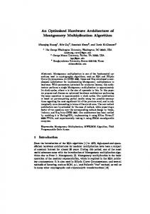
W Nk = e − j 2πk / N F[k] and G[k] are the N/2 point DFTs of f[n] and g[n] respectively. Since both F[k] and G[k] are defined for 0 ≤ k < N / 2 , we need to also evaluate them for N / 2 ≤ k < N ,which is straight forward, using the periodicity and symmetric properties of the DFT: F[k + N/2] = F[k] G[k + N/2] = G[k] Since N is even, then N/2 is also even, then we can further decompose f[n] and g[n] in the same way. If N is a power of 2, then we can repeat the same operation till we expand the DFT equation into N/2 terms of 2-points DFT, which is the radix-2 FFT algorithm. Radix-2 is a derivative of the generic CooleyTukey FFT algorithm, where N is generally decomposed into N1 N2, where N1 is the radix [2]. The generic Cooley-Tukey FFT emerged other algorithms like radix-4, mixed radix, prime factor,…etc [1]. A graphical representation of Radix-2 FFT algorithm is shown in Figure 1 [7].
Figure 1 Decimation-in-time (DIT) Radix-2 FFT algorithm It is clear from Figure 1 that the required number of computations is N/2 Log2N complex multiplies and N Log2N complex adds [7], reducing the complexity to O(N log N).
1.1.1 Decimation-in-time The implementation shown in Figure 1 is called Decimation-in-time (DIT), where the decomposition takes place on the time samples of the input signal x[n]. The algorithm consists of three main steps: 1. Bit-reversal: where the input samples are re-ordered first before the algorithm starts. The reordering is such that; the binary representation of the index of the sample is bit-reversed (see Figure 2), then the sample is re-placed in the buffer at the bit-reversed index instead of the original one.
Figure 2 Bit-reversal for 3 bits index 2. Butterfly: this is the basic 2-points DFT operation (shown in Figure 3 [7]).
Figure 3 simplified butterfly operation 3. Twiddle factor: this is the factor by which the input 2-points are multiplied in the butterfly ( W Nk = e − j 2πk / N ). The value of N and k depends on the stage of the algorithm as shown in Figure 1. They are either stored or calculated on the fly as will be discussed later. Some twiddle factors
requires
no
multiplication,
but
just
negation
or
multiplication
by ± j ,
like W N0 ,W NN / 2 ,WNN / 4 . 1.1.2 Decimation-in-frequency Another version of radix-2 FFT algorithm is the Decimation-in-frequency (DIF) Radix-2 FFT. The derivation of the DIF algorithm is similar to the one discussed in DIT, but in this case we start by the inverse
DFT equation, and factorize the frequency samples of the signal X[k] instead of the time sample. DIF is a derivative of the generic Sande-Tukey algorithm. The steps of the algorithm are different from the DIT case, where the input samples are not bit-reversed, instead the output buffer need to be re-ordered by bitreversal operation to get the correct order of the result. Also, the twiddle factors and butterfly sequence is different from the DIT case. A complete description of DIF can be found in [9]. 2.
HARDWARE IMPLEMENTATION
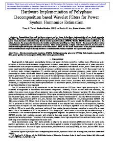
In this section hardware architecture is presented for the FFT processor, to be implemented on FPGA. The goal of the design is to optimize the hardware utilization of the FPGA resources, and achieve a complete butterfly operation in one clock cycle, including the memory access time of two complex samples, which improves the required transform time. In addition, the magnitude of the FFT result is optionally available. The design presented here is a Buffered design architecture, which means that; the input samples should be completely available in the input buffer before the operation of the algorithm can start, and no new inputs can be accepted before the current buffer transform finishes; this is in contrast to other Streaming architectures, where the operation of FFT can occur simultaneously while receiving new input samples. Radix-2 decimation-in-time algorithm was chosen to implement the FFT processor, since it is more suitable for Buffered architectures, because the bit-reversal operation is done at the beginning, which saves the extra re-ordering step at the end of the algorithm. Furthermore, the bit-reversal can be done on the fly in parallel with the buffering step of the input. Also, radix-2 is characterized by its in-place-buffer, which means that; only one buffer is needed through out the whole operation, which saves the memory utilization. Finally, radix-2 FFT algorithm enables using single butterfly core and iterating the calculations on it, which reduces the hardware resources utilizations. The architecture is shown in Figure 4. In the next sub-sections, the components of the architecture are discussed in details.
Figure 4 Memory optimized FFT architecture 2.1.
Bit-reversal
The input samples are supplied in order to the Bit-reversal component, which stores them in a bitreversed order in the input buffer. A counter is kept that increments with every new sample, and the bitreversed index corresponding to this counter is pre-computed for this counter before the sample comes, in this way, the buffering process is done in parallel with the bit-reversal thanks to the algorithm choice of radix-2 DIT FFT. When the counter reaches N samples that means that the input samples are completely buffered. At this point, the Bit-reversal generates the start signal to the Butterfly component and stops receiving new samples till the input buffer is fully transformed. 2.2.
Butterfly
The butterfly operation is shown in Figure 3. The inputs are two complex vectors, and so are the outputs. The operation is equivalent to the basic 2-points DFT. The target of the design is to achieve complete butterfly operation in single clock cycle. This requires reading the real and imaginary components simultaneously of each input vector. Also, both vectors should be read in one clock cycle. This is achieved by optimized memory management architecture discussed in 2.6. The twiddle factors should be ready for the next butterfly operation in only one clock cycle, which will be explained in 2.5.
Finally, having the input vectors and the twiddle factor of the current stage of the algorithm ready, four multiplications and additions should be achieved to generate the four components of the two complex outputs vectors, which requires four multipliers and four adders. 2.3.
Address generator
This component is responsible for generating the following information: •
The addresses to read/write the butterfly inputs/outputs.
•
The index of the twiddle factor according to the algorithm state.
The component is under control of the State machine manager component, which communicates the state of the system to the Address generator, and based on it, the proper addresses are generated. 2.4.
State machine manager
This component is responsible of generating the control signals to other components according to the stage of the algorithm in progress. It monitors the buffering operation after the Bit reversal component, and starts the operation of the rest of the system components if the buffering is over and stops admitting new samples till the FFT transform is completed. It also controls the Address generator operation by communicating the system status to it to generate the proper addresses. Finally, when the algorithm reaches its final stage (stage number Log2N), the optional Magnitude component should start, and the RAM Manager should be notified, so that, the results written to the result buffer is taken from the Magnitude component instead of the Butterfly output. 2.5.
Twiddle factor
The twiddle factors are complex vectors of magnitude equals unity. There are two options available in implementing them; the first one is to store them, and the second one is to calculate them on the fly. The following sub-sections discuss the two options. 2.5.1 Look-up table (time optimized) In this case the values of the complex unity vectors are stored in a LUT, and recalled on need. This optimizes the processing time, since no time is wasted in calculating them. On the other hand, it requires extra memory storage.
Direct analysis shows that 2N entries LUT is needed, where we need N entries for real and imaginary components. However, we can make use of two basic properties: •
The magnitude of the twiddle factors is unity, hence, the real and imaginary components are just the sine and cosine of an angle, so we can only store only one component and deduce the other one from it.
•
The whole waveform of sinusoidal wave can be deduced from only the first quadrant of the waveform.
In this way, we only need to store ¼ N entries LUT. This will be the choice of implementation when time performance is an issue, and N is not so large such that the required memory resources are affordable. 2.5.2 CORDIC (memory optimized) The choice of calculating the twiddle factors whenever needed optimizes the required memory resources, which comes on the expense of the processing time required to perform the calculation. To implement a core that calculates the twiddle factors on the fly, we will use a numerical algorithm called CORDIC (COrdinate Rotation Digital Computer). The CORDIC algorithm is chosen due to two main reasons; first, its hardware implementation is highly optimized, where it utilizes only adders/subtractors, shift registers and one look-up table. This simple hardware can perform a lot of complex functions, ranging between trigonometric, hyperbolic and linear functions, which are the three types of the algorithm. Second, the accuracy of the result is high in small number of iterations, and simple convergence constraints. The main target of the algorithm is to rotate an input complex vector by certain angle; this is called the rotation mode. The other mode is the vectoring mode, where it is required to align the input vector to the x-axis. In addition, the algorithm has three types; Trigonometric, Hyperbolic and Linear. The combination of the three types with the two modes of the algorithm can give a very wide range of complex functions. Details of the algorithm are described in [4].
A simple, configurable hardware is presented in [4], which can be configured to give the sine and cosine of the input angle [4]. In this way, we can apply the twiddle factor argument to the CORDIC core, and obtain the sine/cosine results after certain number of clocks. This choice is available only when memory resources are very limited, especially with large N. 2.6.
RAM Manager
This component is responsible of managing the two RAM buffers for real and imaginary intermediate results of the algorithm, each of size N entries; hence, they can be accessed simultaneously in one clock cycle. The same buffers are used to hold the input samples and the result. To enable reading/writing the two inputs/outputs of the butterfly in one clock cycle, the dual-port RAM property of the on-chip memory of the used Cyclone III FPGA was exploited, where two entries of each RAM (real or imaginary) can be read simultaneously in one cycle. In case magnitude output option, the RAM manager acts as MUX, where the memory access is given to the Butterfly component output in all the stages of the algorithm, except the last one, where the RAM access will be given to the Magnitude output component. 2.7.
Magnitude calculation (optional)
Many applications require the magnitude of the result of transformation rather than the complex results, like the one in [7]. In our design, the user can choose between having the results in the in-place buffers as complex vectors, or as magnitude of these vectors, in which case the imaginary buffer will be useless, and the actual results are valid in the real buffer only. To calculate the magnitude of the complex vectors of the result buffers, CORDIC algorithm discussed in 2.5.2 is used in its Trigonometric type and vectoring mode with certain configuration described in [4]. 2.8.
Fixed-point width
Internal and interfacing signal widths as well as fraction and integer parts widths are completely configurable to afford the dynamic range of different applications. The module was real-time tested in a Distributed Speech Recognition (DSR) system [7], where all signals were fixed to 16 bits width of signed numbers.
3. 3.1.
RESULTS
Hardware utilization
The design presented above was implemented using VHDL language and synthesised on Altera Cyclone III EP3C40F780C8 device. Table 1 shows the hardware utilization results for two values of N; 256 and 512 points. The results include the optional Magnitude calculation component. Look-up table implementation of twiddle factors is used, see 2.5.1. N
Logic elements
Multipliers
Memory bits
256
2,314
4
9,232
512
2,314
4
18,448
Table 1 Hardware utilization results The results show that the design is scalable in terms of logic elements and multipliers, while memory resources utilization increases linearly with N. This is as expected since the same butterfly core is used for all values of N, while the LUT and in-place buffers sizes increases with N. 3.2.
Processing time performance
In case of LUT implementation of twiddle factors, the processing time equation will be: Processing time = N /2 × M + N/2 × Log2N where M is the time taken by the Magnitude CORDIC core. In case of CORDIC implementation of twiddle factors, the processing time equation will be: Processing time = N /2 × log2 N + C ×
log 2 N −1
∑2
i
+M
i =0
where C is the time taken by the CORDIC core used to calculate the twiddle factors, while M is the time taken by the CORDIC core used to calculate the magnitude of the output. Table 2 gives summary of real time results of the time performance results in case of time and memory optimized implementation of twiddle factors. Assuming M = 11 and C = 12.
N
No. of clocks
LUT
256
2432
LUT
512
4864
CORDIC
256
4107
CORDIC
512
8459
Table 2 Time performance results 4.
RELATED WORK
Table 3 shows the comparison between Altera’s reference design of the FFT (Burst data flow architecture, 256 points, single output, 16 bits signal width) [11], other designs [5] and [6], and the FFT presented here, in the time optimized solution. All designs have 16 bits fixed point signal length, and 256 point FFT length. The Magnitude calculation optional component is not considered, so all designs have complex outputs. FPGA
Logic Elements
Memory
Multipli-
Clock Cycle
(Bits)
ers
Count
(18X18) Altera [11]
Cyclone III
1,463
9,472
4
1628
6,702
20480
48
43
1,334
--
--
--
998
9,232
4
1024
EP3C10F256C6 Design in [5]
Stratix II EP2S15F672C3
Design in [6]
Stratix II EP2S60F1020C4
Front end FFT
Cyclone III EP3C10F256C6
(18X18)
Table 3 FFT benchmarking against other designs
The results in Table 3 show that the FFT design presented here outperforms Altera reference design in terms of hardware utilization of logic elements and memory bits, while they both utilize 4 18x18 multipliers. In terms of time performance, the local FFT design takes 1024 cycles to finish, while the reference design takes 1628 cycles, which means that the reference design takes 1.58 times as that of the local FFT design. The design in [5] is very efficient in terms of clock cycles count, however, this comes on the expense of hardware, memory and multipliers resources usage. 5.
CONCLUSION
In this paper, optimized hardware architecture of radix-2 Fast Fourier Transform algorithm was presented. The novel aspects presented here are represented in the efficient utilization of the algorithm properties to optimize the hardware resources usage rather than optimizing the algorithm itself. Thanks to the choice of DIT radix-2 algorithm, parallelism was possible between input buffering and initial bit-reversal. Also, using single butterfly core optimized the hardware utilization, keeping the logic elements usage nearly constant with N, while the memory resources are the only resources affected by the increase of the transform size, which improves the design scalability. On the other hand, the inherited features of the underlying hardware were exploited to optimize the design. For example, using the dual-port RAM feature of the on-chip memory of the used FPGA helped to achieve the butterfly operation in single clock cycle, which improved the time performance. Two options are available to implement the twiddle factors, which suits both applications that are memory or time critical. Finally, to address the need of many applications to obtain the magnitude of the FFT instead of the complex result, an optional magnitude output stage is added. CORDIC algorithm was chosen to implement this unit due to the hardware simplicity of the CORDIC core implementation. The results of the design are compared to other designs in addition to reference designs provided by Altera on the same FPGA used here, which showed improved performance of the design over corresponding references.
REFERENCES [1] Xudding Huang, Alex Acero, Hsiao-Wuen Hon, " Spoken Language Processing, A guide to Theory, Algorithm, and System Development ", Prentice Hall, 2001. [2] Cooley, James W., and John W. Tukey, "An algorithm for the machine calculation of complex Fourier series," Mathematics of Computation 19 (Apr.), 297–301 (1965). [3] Steven G. Johnson and Matteo Frigo, " A modified split-radix FFT with fewer arithmetic operations ", IEEE Transactios, Signal Processing, vol. 55, pp. 111-119, Jan. 2007. [4] Ray Andraka, " A survey of CORDIC algorithms for FPGA based computers ", in Proceedings of the 1998 ACM/SIGDA sixth international symposium on Field programmable gate arrays, California, USA, 1998. [5] Jesús García; Juan A. Michell; Gustavo Ruiz; Angel M. Burón, " FPGA realization of a Split Radix FFT processor ", Proceedings of SPIE--The International Society for Optical Engineering, Vol 6590, May 2007. [6] C. González-Concejero, V. Rodellar, A. Álvarez-Marquina, E. Martínez de Icaya and P. GomezVilda,
"
A
portable
hardware
design
of
a
FFT
algorithm
",
Latin American Applied Research, vol. 37 no.1, March 2007. [7] Ahmad A. Al Sallab, Hossam Fahmy, Mohsen Rashwan" Hardware Implementation of Distributed Speech Recognition System Front End ", in Proceedings of 17th European Signal Processing Conference, Glasgow, Scottland, 24-28 August 2009. [8] Douglas L. Jones, " Decimation-in-time (DIT) Radix-2 FFT ", Connexion project, Version 1.7: Sep 15, 2006 7:46 am GMT-5, http://cnx.org/content/m12016/1.7/ [9] Douglas L. Jones, " Decimation-in-frequency (DIF) Radix-2 FFT ", Connexion project, Version 1.6: Sep 17, 2006 8:47 am GMT-5, http://cnx.org/content/m12018/1.6/ [10] Altera,
"
CORDIC
reference
design
",
Altera
Application
Note,
AN:
263,
www.altera.com/products/ip/dsp/ipm-index.jsp, June 2005. [11] Altera, " FFT MegaCore function User Guide ", Altera MegaCore documentation and user guides, UG-FFT-7.0, www.altera.com/products/ip/dsp/ipm-index.jsp, November 2008.