Optimized Interval Splitting ∗ in a Linear Scan Register Allocator Christian Wimmer
Hanspeter Mossenb ¨ ock ¨
Institute for System Software Johannes Kepler University Linz Linz, Austria
Institute for System Software Johannes Kepler University Linz Linz, Austria
[email protected]
[email protected]–linz.ac.at
ABSTRACT
1. INTRODUCTION
We present an optimized implementation of the linear scan register allocation algorithm for Sun Microsystems’ Java HotSpotTM client compiler. Linear scan register allocation is especially suitable for just-in-time compilers because it is faster than the common graph-coloring approach and yields results of nearly the same quality. Our allocator improves the basic linear scan algorithm by adding more advanced optimizations: It makes use of lifetime holes, splits intervals if the register pressure is too high, and models register constraints of the target architecture with fixed intervals. Three additional optimizations move split positions out of loops, remove register-to-register moves and eliminate unnecessary spill stores. Interval splitting is based on use positions, which also capture the kind of use and whether an operand is needed in a register or not. This avoids the reservation of a scratch register. Benchmark results prove the efficiency of the linear scan algorithm: While the compilation speed is equal to the old local register allocator that is part of the Sun JDK 5.0, integer benchmarks execute about 15% faster. Floating-point benchmarks show the high impact of the Intel SSE2 extensions on the speed of numeric Java applications: With the new SSE2 support enabled, SPECjvm98 executes 25% faster compared with the current Sun JDK 5.0.
Register allocation is one of the most profitable compiler optimizations. It is the task of assigning physical registers to local variables and temporary values. The most commonly used algorithm treats the task of register allocation as a graph-coloring problem [1][2]. It uses an interference graph whose nodes represent the values that should get a register assigned. Two nodes are connected with an edge if they are live at the same time, i.e. when they must not get the same register assigned. Then the graph is colored such that two adjacent nodes get different colors, whereby each color represents a physical register. The graph-coloring algorithm generates code of good quality, but is slow for just-in-time compilation of interactive programs because even heuristic implementations have a quadratic runtime complexity. In comparison, the linear scan algorithm is simpler and faster and yields results of nearly the same quality. Lifetime intervals store the range of instructions where a value is live. Two intersecting intervals must not get the same register assigned. The algorithm assigns registers to values in a single linear pass over all intervals. The basic linear scan algorithm [12][13] can be extended to support holes in lifetime intervals and the splitting of intervals [17]. We implemented and extended the linear scan algorithm for the Java HotSpotTM client compiler [4] of Sun Microsystems. The compiler is invoked by the Java HotSpotTM VM [16] for frequently executed methods. The client compiler is designed as a fast compiler that omits time-consuming optimizations, achieving a low startup and response time. For this reason, the current product version of the client compiler uses only a local heuristic for register allocation. In contrast, the Java HotSpotTM server compiler [10] produces faster executing code, but at the cost of a more than ten times higher compilation time. This is not suitable for client applications because of the higher response time. Linear scan register allocation for the client compiler reduces the gap of peak performance between the two compilers without degrading the response time of the client compiler. This paper presents the details of a successful implementation of the linear scan algorithm for a production-quality just-in-time compiler. The paper contributes the following:
Categories and Subject Descriptors D.3.4 [Programming Languages]: Processors—Compilers, Optimization, Code generation
General Terms Algorithms, Languages, Performance
Keywords Java, compilers, just-in-time compilation, optimization, register allocation, linear scan, graph-coloring ∗This work was supported by Sun Microsystems, Inc.
• We introduce use positions to decide which interval is to be spilled. They mark instructions where a lifetime interval should or must have a register assigned.
Permission to make digital or hard copies of all or part of this work for personal or classroom use is granted without fee provided that copies are not made or distributed for profit or commercial advantage and that copies bear this notice and the full citation on the first page. To copy otherwise, to republish, to post on servers or to redistribute to lists, requires prior specific permission and/or a fee. VEE’05, June 11–12, 2005, Chicago, Illinois, USA. Copyright 2005 ACM 1-59593-047-7/05/0006...$5.00.
• We present three fast optimizations—optimal split positions, register hints and spill store elimination—that improve the code quality without a data flow analysis.
132
• We compare our research compiler with the client compiler and the server compiler of the Sun JDK 5.0. The measurements show that the linear scan algorithm decreases the run time of compiled code without increasing the compilation time when compared with the product client compiler.
2.
are also used to determine when a spilled interval must be reloaded into a register. Each use position has a flag denoting whether it requires the value of the interval to be in a register or not: If the use position must have a register, the register allocator guarantees that the interval has a register assigned at this position. If the interval was spilled to memory before this position, it is reloaded into a register. This avoids the reservation of a scratch register for temporary computations. If the use position should have a register, then the interval may be spilled. This allows the modeling of machine instructions of the IA-32 architecture that can handle memory operands. Together with the lifetime intervals, use positions form a clear interface between the register allocator and the rest of the compiler. This is beneficial for the speed of the allocation because accessing the LIR, especially iterating over instructions or operands, was identified as the most timeconsuming part. To get the next use of an interval, we must access only the next element in the list without scanning multiple instructions. Changes in the LIR, e.g. the addition of new instructions, do not require any change in the register allocator. Additionally, use positions avoid platformdependent code in the allocator.
DATA STRUCTURES
Our version of the HotSpotTM client compiler uses two intermediate representations: When a method is compiled, the front end transforms bytecodes to the graph-based highlevel intermediate representation (HIR) that uses SSA form [3][8]. Several optimizations are applied before the back end converts the HIR to the low-level intermediate representation (LIR). After linear scan register allocation, machine code is created from the LIR. More details of the compiler architecture can be found in [18]. The compiler can generate code for the Intel IA-32 architecture and the SPARC architecture of Sun. The examples and measurements in this paper are given for the IA-32 architecture.
2.1 Intermediate Representation The linear scan algorithm operates on the LIR that is conceptually similar to machine code. It allows platformindependent algorithms that would be difficult to implement directly on machine code. Each basic block of the control flow graph stores a list of LIR instructions. Before register allocation, all basic blocks are sorted into a linear order: The control flow graph is flattened to a list using the standard reverse postorder algorithm. To improve the locality, all blocks belonging to a loop are emitted consecutively. Rarely executed blocks such as exception handlers are placed at the end of the method. An operand of a LIR instruction is either a virtual register, a physical register, a memory address, a stack slot of the stack frame, or a constant. While the number of virtual registers is unlimited, the number of physical registers is fixed by the target architecture. When the LIR is generated, most operands are virtual registers. The register allocator is responsible for replacing all virtual registers by physical registers or stack slots.
2.4 Fixed Intervals Some machine instructions require their operands in fixed registers. Such constraints are already considered during the construction of the LIR by emitting physical register operands instead of virtual register operands. Although the register allocator must leave these operands unchanged, they must be considered during register allocation because they limit the number of available registers. Information about physical registers is collected in fixed intervals. For each physical register, one fixed interval stores where the register is not available for allocation. Use positions are not needed for fixed intervals because they are never split and spilled. Register constraints at method calls are also modeled using fixed intervals: Because all registers are destroyed when the call is executed, ranges of length 1 are added to all fixed intervals at the call site. Therefore, the allocation pass cannot assign a register to any interval there, and all intervals are spilled before the call.
2.2 Lifetime Intervals
2.5 Example
For each virtual register, a lifetime interval is constructed that stores the lifetime of the register as a list of disjoint ranges. In the simplest case, there is only a single live range that starts at the instruction defining the register and ends at the last instruction using the register. More complicated intervals consist of multiple ranges. The space between two ranges is commonly referred to as a lifetime hole. In order to create accurate live ranges, a data flow analysis is performed before the intervals are built. This is necessary to model the data flow in a non-sequential control flow. For example, an operand that is used once in a loop must be alive in the entire loop; otherwise it would not be available in further iterations.
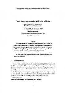
Figure 1 illustrates the lifetime intervals for an instruction sequence. The four virtual registers v1 to v4 are represented by the intervals i1 to i4. Use positions are denoted by black bars. The fixed intervals of all registers but ecx are collapsed to a single line because they are equal. The interval i1 has a lifetime hole from 10 to 24, which allows the allocator to assign the same register to i1 and i2. The shift instruction requires the second operand in the fixed register ecx, so a range from 20 to 22 is added to the fixed interval for ecx. All registers are destroyed at the call instruction 16, so a short range of length 1 is added to all fixed intervals. To allow ranges that do not extend to the next instruction, the instruction numbers are always incremented by 2, i.e. only even numbers are used. Therefore, the ranges from 16 to 17 do not interfere with the allocation of i4 starting at 18. Additionally, the numbering by two allows the allocator to insert spill loads and stores at odd positions between two instructions.
2.3 Use Positions The use positions of an interval refer to those instructions where the virtual register of this interval is read or written. They are required to decide which interval is to be split and spilled when no more physical registers are available. They
133
10: 12: 14: 16: 18: 20: 22: 24:
v2 = v1 v3 = 10 v3 = v3 + v2 call foo() v4 = v3 ecx = v2 v4 = v4