It has the capability to adjust the width of the linear expansion each clock cycle. ... scheme is simple yet very effective. 1. ... application time as well as the bandwidth requirements. A number of ... Linear expansion schemes can be divided into those that use .... used to load either just a single block (by activating only the scan.
Adjustable Width Linear Combinational Scan Vector Decompression C.V. Krishna and Nur A. Touba Computer Engineering Research Center University of Texas, Austin, TX 78712-1084 E-mail: {krishna, touba}@ece.utexas.edu decompression schemes involve placing a combinational circuit between the tester channels and the scan chains that expands a small number of tester channels, N, to fill a much larger number of scan chains, M. Two basic schemes have been proposed for combinational linear decompression. The very simplest is the Illinois Scan Architecture [6, 8], in which one channel from the tester is used to feed multiple scan chains. Another scheme is the one described in [1] which involves using a network of XOR gates such that each scan chain is fed from some linear combination of the channels from the tester.
Abstract A new scheme for combinational linear expansion is proposed for decompression of scan vectors. It has the capability to adjust the width of the linear expansion each clock cycle. This eliminates the requirement that every scan bit-slice be in the output space of the linear decompressor. Depending on how specified the current bit-slice is, the decompressor may load all scan chains or may load only a subset of the scan chains. This provides the nice feature that any scan vector can be generated using the proposed scheme regardless of the number or distribution of the specified bits. Thus, the proposed scheme allows the use of any ATPG procedure without any constraints. Moreover, it allows greater compression to be achieved than fixed width expansion techniques since the ratio of the number of scan chains to the number of tester channels can be scaled much larger. A procedure for designing and optimizing the adjustable width decompression hardware and obtaining the compressed data is described. Experimental data indicates that the proposed scheme is simple yet very effective.
Scan Chain 1
N Channels from Tester
Scan Chain 2
Scan Chain M
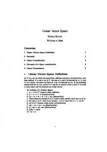
Figure 1. Combinational Linear Decompression
1. Introduction
In this paper, a new scheme is proposed for combinational linear expansion that has some nice advantages. One of the drawbacks of the scheme in [1] is that in every clock cycle, an entire “bit-slice” of the scan chains (which consists of M bits) must be filled. Thus, the most specified bit-slice places an upper bound on the compression ratio of M/N. In order to keep the compression ratio high, some constraints need to be placed on the ATPG process so that no bit-slice has too many specified bits such that it cannot be generated through the linear expansion network. Placing constraints on the ATPG process can result in generating more test vectors thereby offsetting some of reduction in test data gained through using compression. In the proposed scheme, an adjustable width linear expansion technique is used. Whereas the scheme in [1] always uses a fixed expansion width of N bits to fill M scan chains in every clock cycle, the proposed approach provides the capability of using different size expansions. In any given clock cycle, the N bits coming from the tester may expand to load all M scan chains, or may load only a subset of the scan chains. This provides some nice benefits. It eliminates the requirement that every scan bit-slice has to be in the output space of the linear decompressor. The decompressor can be designed so that any scan vector can be generated using the proposed scheme regardless of the number or distribution of the specified bits (as explained in Sec. 3). Thus, the proposed scheme allows the use of any ATPG procedure without any constraints. Moreover, it allows greater compression to be achieved. The ratio of M/N can be scaled much larger. For lightly specified bit-slices, the proposed scheme can use a full N to M expansion, while for more heavily specified bit-slices, it can use a smaller width expansion. This flexibility allows for better encoding efficiency and hence more compression.
Many test vector compression schemes have been proposed to reduce the tester storage requirements by reducing the test data volume. Reducing the test data volume helps to reduce the test application time as well as the bandwidth requirements. A number of test vector compression schemes have been developed using a variety of codes including run-length codes [9], selective Huffman codes [10], Golomb codes [2], frequency directed codes [3], Mutation codes [18], packet-based codes [20], and nonlinear combinational codes [19]. Another class of schemes involves reducing test vector volume by encoding test vectors in a longer built-in self-test (BIST) test sequence. These techniques include using hybrid patterns [4], folding counters [7], two-dimensional compression [16], and RESPIN [5]. A third major class of test vector compression schemes are based on linear expansion. The data is decompressed by performing only linear operations. This includes techniques based on linear feedback shift register (LFSR) reseeding and combinational linear expansion circuits consisting of XOR gates. Linear expansion circuits exploit the unspecified (don’t care) bit positions in test cubes (i.e., deterministic test vectors where the unassigned bit positions are left as don’t cares) to achieve large amounts of compression. It has been observed that typically only 1-5% of the bits are specified. Linear expansion schemes can be divided into those that use sequential linear finite state machines and those that use only linear combinational circuits. The schemes that use linear finite state machines include [11, 12, 13, 14, 15, 17, 21]. The schemes that use only linear combinational circuits provide less compression, but require less overhead and are simpler and easier to implement. As illustrated in Fig. 1, the combinational linear Permission to make digital or hard copies of all or part of this work for personal or classroom use is granted without fee provided that copies are not made or distributed for profit or commercial advantage and that copies bear this notice and the full citation on the first page. To copy otherwise, to republish, to post on servers or to redistribute to lists, requires prior specific permission and/or a fee. ICCAD’03, November 11-13, 2003, San Jose, California, USA. Copyright 2003 ACM 1-58113-762-1/03/0011 ...$5.00.
N-to-M Comb. Linear Expand
863
assigned only a limited number of values. The number of control bits, p, required to select the grouping factor, g, each clock cycle is given by: p = élog2( # of possible values of g )ù The N bits coming from the tester each clock cycle must encode the p control bits for the grouping factor and the corresponding blocks of the bit-slice. The control logic shown in Fig. 2 decodes the p control bits for the grouping factor from the N bits coming from the tester. The control logic also keeps track of the block that was loaded last during the previous clock cycle, since the blocks to be loaded during the current cycle will start after this block. The control logic thus needs a élog2(k)ù bit index register that points to the last block that was loaded in the previous clock cycle. Based on the value of this index register and the grouping factor, the control logic selects the set of scan clocks that need to be activated in the current clock cycle. The index register is updated in the current cycle by adding the grouping factor to the contents of the register by performing a mod-k addition so that it points to the last block that was loaded. Consider the operation of the hardware in Fig. 2. During each clock cycle, the tester feeds N bits to the linear decompressor and the control logic. Since the linear decompressor is a combinational network, the M outputs of the decompressor are ready with the decoded data within the same cycle. Based on the N bits from the tester, the control logic activates the appropriate set of scan clocks. The remaining scan clocks are left inactive. For example, if block B1 was loaded last during the previous clock cycle, and the grouping factor for the current clock cycle is 2, then blocks B2 and B3 are loaded during the current clock cycle. Only the scan clocks SC2 and SC3 are activated during the current clock cycle. Note that blocks across different bit-slices can also be loaded within the same clock cycle. If block Bk-1 was the last block to be loaded in the previous clock cycle and the grouping factor is 3, then in the current clock cycle, the scan clocks, SC1, SC2, and SCk will be activated. This will cause block Bk from the first bit-slice and blocks B1 and B2 from the second bit-slice to be loaded. Thus, during each clock cycle, at most k blocks can be loaded, though not necessarily from the same bit-slice (as it may wrap to the next bit-slice). This process continues until all the bit-slices are loaded. At this point, the system clock can be applied and the response from the circuit loaded into the scan chains. Note that no wrapping is done across scan vectors. A multiple input signature register (MISR) can be used to compress the output response as it is shifted out of the scan chains while the next scan vector is being loaded. In conventional scan testing, the output response stored in an entire bit-slice is shifted into the MISR during each clock cycle. However, note that in the proposed scheme, when not all the blocks in a bit-slice are loaded in a single clock cycle, only a subset of the scan chains are shifted in that clock cycle. The scan-out for the inactive scan chains will simply hold the same value as the last clock cycle. This does not cause any problems for the MISR operation as it will simply compact the scan-out of all the scan chains each clock cycle regardless of whether each scan chain is active or not.
2. Overview of Proposed Scheme The key idea of the proposed scheme is that the N bits coming from the tester each clock cycle need not load exactly one complete bit-slice of the scan chains. Based on the number of specified bits in the bit-slice, the N bits can be used to encode either a portion of the bit-slice (for a bit-slice having a high number of specified bits) or an entire bit-slice (for low number of specified bits). Hence the bit-slice with the maximum number of specified bits does not place a lower bound on the number of tester channels required, since multiple tester cycles can be used to load the bit-slice. No special ATPG is thus required to distribute the specified bits evenly across the bit-slices. The architecture of the proposed scheme is shown in Fig. 2. The N bits from the tester are connected to a combinational linear decompressor. The outputs of the decompressor feed the scan chains within the circuit. If there are M scan chains, the linear decompressor has M outputs. Each bit-slice of the scan chains is divided into k equal sized blocks, B1 through Bk , where each block has q bits. Thus, the number of blocks, k, is equal to M/q. The scan chains are effectively partitioned into k groups, corresponding to the blocks B1 though Bk. Each of these scan groups has a separate scan clock associated with it. As can be seen from Fig. 2, the first q scan chains corresponding to block B1 are clocked by scan clock SC1, and the last q scan chains corresponding to block Bk are clocked by scan clock SCk. These scan clocks are generated by the control logic shown in Fig. 2. Chip
m-bit Scan Chains SC 1
Scan Chain 1 B1
N bits from tester
SC 1
M I S R
Scan Chain q
Linear Decompressor (N x M) SC k
Scan Chain ( k -1)q+1 Bk
SC k
Control Logic
Scan Chain k q
SC 1 SC k
Figure 2. Architecture of Proposed Scheme Using this architecture, an adjustable width linear expansion can be implemented. The N bits coming from the tester can be used to load either just a single block (by activating only the scan clock for that block) or multiple blocks. There would be no compression achieved when N is used to load just a single block (this would occur when the block to be encoded has a very high number of specified bits). However, the compression would be high when the N bits are used to load a large number of blocks at a time (this would occur when successive blocks have very few specified bits). The number of blocks that is loaded in a clock cycle can be termed as the grouping factor g. Some control information is needed to select the grouping factor that is used in each clock cycle. For example, if g can take the values 1, 2, 4 and 16, then two control bits would be required to encode these four possible values of g. To minimize the control information, g should be
3. Design of Linear Combinational Decompressor It is important that the linear combinational decompressor be designed in such a way that it is always possible to encode all scan vectors regardless of the number and distribution of the
864
proposed scheme. N is fixed by the available tester bandwidth, since N is the number of bits coming from the tester every tester cycle. The designer can select whatever number, M, of scan chains is desired. The amount of compression will improve as the number of scan chains is increased, but the overhead of the decompressor increases as well and there are diminishing marginal returns as the number of scan chains becomes large. Note that there may be other design factors that also impact how many scan chains the designer wishes to use. So given a fixed N and M, the remaining parameters to select are the number of control bits, p, and the corresponding set of grouping factors. Once p is chosen, then the size of each block, q, is equal to N-p, and the number of blocks (k) per scan bit-slice is equal to M/q. As the number of control bits is increased, more grouping factors are possible which improves encoding efficiency. However, this is offset by the additional data required for the control bits. At some point, the marginal gains in encoding efficiency do not compensate for the additional data required for adding another control bit. Figure 3 shows an example of how the amount of compressed test data varies with the number of control bits for the s13207 benchmark circuit. As can be seen, it reaches a minimum when p=3 and increases thereafter.
specified bits. This eliminates the need for any special constraints on the ATPG process. To accomplish this, the linear combinations of the channels coming from the tester that are used to drive each scan chain need to be carefully selected to ensure that it is always possible to solve for at least one block in each clock cycle. The linear decompressor consists of XOR gates driving the scan-ins of each of the M scan chains (one XOR gate per scan chain). The inputs to each XOR gate are a subset of the N channels from the tester. Thus, each scan chain is driven by some linear combination of the N channels from the tester. The key is to choose the linear combinations for each scan chain in such a way that it is always possible to solve for at least one block. To accomplish this, the parameters for the architecture of the proposed scheme should be selected so that N = p+q, where p is the number of control bits and q is the block size. Then the following procedure can be used for selecting the linear combinations. First select the linear combinations for the p control bits so that they are linearly independent of each other. This ensures that any combination of the control bits can be generated each clock cycle. Then for each block of q scan chains, the linear combinations for each scan chain are chosen so that they are linearly independent of each other and linearly independent of the linear combinations of the p control bits. This ensures that any combination of specified bits for the block can be generated. Forming the p+q linearly independent combinations is always possible to do provided N is not less than p+q. By increasing the number of inputs to the XOR gates, the space of possible linear combinations increases (it is maximum for N/2). This allows more diversity in the linear combinations across different blocks, however, it comes at the cost of more overhead. As shown in [1], good results can typically be obtained using just 3-input XOR gates. For the proposed decompression scheme, each scan vector is encoded by starting from the first block in the first bit-slice. The largest grouping factor is tried first. For each specified bit in the set of consecutive blocks corresponding to the largest grouping factor, a linear equation is formed corresponding to the XOR gate that is driving its scan-in. A linear equation is also formed for each of the p control bits so that it takes on the correct value corresponding to the largest grouping factor. The system of linear equations for all the specified bits in the set of blocks and the p control bits is then passed to a linear solver. If a solution cannot be found, then the next smaller grouping factor is tried and so forth. In the worst case, it may be necessary to go all the way down to the smallest grouping factor which will correspond to just a single block. This is guaranteed to have a solution since all the linear equations of a block will be independent due to the way the linear decompressor was designed. When the linear solver does find a solution, then the solution gives the values for the N bits coming in from the tester for that clock cycle, and the encoding process then continues for the next set of blocks in the same manner. This process continues until all the blocks of the scan vector have been encoded. A more detailed description of how to form and solve the linear equations can be found in [12] and [14].
70,000 68,000 66,000 64,000
Test Data
62,000 60,000
20,000 18,000 16,000 14,000 12,000 10,000 0
1
2
3
4
5
6
7
Number of Control Bits (p)
Figure 3. Total Compressed Data versus Number of Control Bits for s13207 Benchmark Circuit So the procedure for selecting the number of control bits is as follows. First try to encode all the scan vectors using full N to M expansion which corresponds p=0, i.e., having no control bits (which is the same as [1]). If this is possible, then that is the best solution for those values of M and N. If it is not possible, then try p=1. This allows 2 different grouping factors. One can be a grouping factor of 1 and the other a grouping factor of k. The test cubes can be encoded using these two grouping factors to compute the total amount of compressed test data. Then try p=2. This allows 4 different grouping factors. For simplicity, they can be selected to be equally spaced between 1 and k. Again the total amount of compressed test data can be calculated. This process continues with p increasing by one each time until a point is reached where increasing p does not reduce the total test data. This procedure allows the minimum point in the graph to be found thereby giving the best value for p to minimize the total amount of compressed test data. One simplification in the procedure above is that the grouping factors are chosen to be equally spaced between 1 and k. This may not give the most efficient set of grouping factors.
4. Selecting Architecture Parameters Given the set of test cubes (test vectors where the unspecified inputs are left as don’t cares) and the tester bandwidth available, this section describes how to select the parameters for the
865
cost solution for achieving an order of magnitude reduction in test data volume.
An optimization for the procedure would be to first assume all grouping factors are possible, and then encode the scan vectors and keep track of how often each grouping factor is used. Given the frequency with which each grouping factor is used, a more optimal set of grouping factors can be chosen.
Acknowledgements This material is based on work supported in part by the Intel Corporation and in part by the National Science Foundation under Grant No. CCR-0306238.
5. Experimental Results Experiments were performed on the largest ISCAS 89 benchmark circuits. For each circuit, ATPG was performed to generate test cubes for the non-redundant faults. The test cubes were then encoded using the proposed scheme. The results are shown in Table 1. The number of test cubes for each circuit is shown. The set of test cubes was encoded using the proposed scheme assuming 19 channels coming from the tester. Results are shown for using 1, 2, and 3 control bits. In each case, the total amount of required tester storage (including the control bits) is shown followed by the percent compression. Table 2 provides a comparison between the proposed method and the linear combinational decompressor scheme in [1] which uses a fixed width expansion. While the proposed scheme does not require any special ATPG as it is guaranteed to work for any set of test cubes, the scheme in [1] requires a special constrained ATPG to ensure all test cubes can be encoded. Note that if the proposed method was combined with a special ATPG procedure, the results could be improved significantly. Nonetheless, the proposed scheme performs very well as the adjustable width expansion allows better encoding efficiency compared with a fixed width expansion even without any modifications to the ATPG.
References [1] Bayraktaroglu, I., and A. Ogailoglu, “Test Volume and Application Time Reduction Through Scan Chain Concealment,” Proc. of Design Autom. Conf., pp. 151-155, 2001. [2] Chandra, A., and K. Chakrabarty, “Test Data Compression for System-on-a-Chip Using Golomb Codes,” Proc. of VLSI Test Symposium, pp. 113-120, 2000. [3] Chandra, A., and K. Chakrabarty, “Frequency-Directed Run Length (FDR) Codes with Application to System-on-a-Chip Test Data Compression,” Proc. of VLSI Test Symp., pp. 42-47, 2001. [4] Das, D., and N.A. Touba, “Reducing Test Data Volume Using External/LBIST Hybrid Test Patterns,” Proc. of International Test Conference, pp. 115-122, 2000. [5] Dorsch, R., and H.-J. Wunderlich, “Tailoring ATPG for Embedded Testing,” Proc. of Int. Test Conf., pp. 530-537, 2001. [6] Hamzaoglu, I., and J.H. Patel, “Reducing Test Application Time for Full Scan Embedded Cores,” Proc. of Int. Symposium on Fault Tolerant Computing, pp. 260-267, 1999. [7] Hellebrand, S., H.-G. Liang, and H.-J. Wunderlich, “A Mixed Mode BIST Scheme Based on Reseeding of Folding Counters,” Proc. of Int. Test Conference, pp. 778-784, 2000. [8] Hsu, F.F., K. M. Butler, J. H. Patel, “A Case Study on the Implementation of the Illinois Scan Architecture,” Proc. of International Test Conference, pp. 538-547, 2001. [9] Jas, A., and N.A. Touba, "Test Vector Decompression Via Cyclical Scan Chains and Its Application to Testing Core-Based Designs", Proc. of Int. Test Conference, pp. 458-464, 1998. [10] Jas, A., J. Ghosh-Dastidar, and N.A. Touba, "Scan Vector Compression/Decompression Using Statistical Coding", Proc. of VLSI Test Symposium, pp. 114-120, 1999. [11] Jas, A., B. Pouya, and N.A. Touba, “Virtual Scan Chains: A Means for Reducing Scan Length in Cores”, Proc. of VLSI Test Symposium, pp. 73-78, 2000. [12] Könemann, B., “LFSR-Coded Test Patterns for Scan Designs,” Proc. of European Test Conference, pp. 237-242, 1991. [13] Könemann, B., “A SmartBIST Variant with Guaranteed Encoding” Proc. of Asian Test Symposium, pp. 325-330, 2001. [14] Krishna, C.V., A. Jas, and N.A. Touba, "Test Vector Encoding Using Partial LFSR Reseeding", Proc. of International Test Conference, pp. 885-893, 2001. [15] Krishna, C.V., and N.A. Touba, "Reducing Test Data Volume Using LFSR Reseeding with Seed Compression ", Proc. of International Test Conference, pp. 321-330, 2001. [16] Liang, H.-G., S. Hellebrand, and H.-J. Wunderlich, “TwoDimensional Test Data Compression for Scan-Based Deterministic BIST,” Proc. of International Test Conference, pp. 894-902, 2001. [17] Rajski, J., et al., “Embedded Deterministic Test for Low Cost Manufacturing Test,” Proc. of Int. Test Conf., pp. 301-310, 2002. [18] Reda, S., and A. Orailoglu, “Reducing Test Application Time Through Test Data Mutation Encoding”, Proc. of Design, Automation, and Test in Europe, pp. 387-393, 2002. [19] Reddy, S., K. Miyase, S. Kajihara, and I. Pomeranz, “On Test Data Volume Reduction for Multiple Scan Chain Designs”, Proc. of VLSI Test Symposium, pp. 103-108, 2002. [20] Volkerink, E.H., A. Khoche, and S. Mitra, “Packet-based Input Test Data Compression Techniques,” Proc. of International Test Conference, pp. 154-163, 2002. [21] Volkerink, E.H., and S. Mitra, “Efficient Seed Utilization for Reseeding based Compression,” Proc. VLSI Test Symposium, 2003.
Table 1. Results using 1, 2, and 3 Control Bits Circuit
p=1
p=2
p=3
Name
Num Cubes
Test Data
% Comp
Test Data
% Comp
Test Data
% Comp
s13207 s15850 s38417 s38584
266 226 376 296
68,134 85,823 197,334 197,182
63.4 37.8 68.4 54.4
16,378 22,895 51,623 42,997
91.2 83.4 91.7 90.0
14,307 15,067 49,001 28,994
92.3 89.0 92.1 93.3
Table 2. Comparison with Scheme Described in [1] Circuit Name s13207 s15850 s38417 s38584
[1] Tester Num Channels Cubes 24 251 32 170 32 296 24 182
Proposed Scheme Test Tester Num Test Data Channels Cubes Data 19 266 14,307 24,096 19 226 15,067 16,320 19 376 49,001 63,936 19 296 28,994 34,944
6. Conclusions The proposed scheme for adjustable width linear combinational expansion is simple to implement, yet it efficiently exploits the don’t care values in the test set to reduce test data storage requirements. The overhead for the proposed scheme is small. It consists of one 3-input XOR gate for each scan chain, a small amount of control logic, and an index register. The computational complexity for solving the linear equations is O(N2M) where N is the number of channels from the tester and M is the number of scan chains. Hence, it can be done very rapidly. Thus, the proposed scheme is very practical and provides a low
866