Optimizing coverage in mobile wireless sensor networks Silvester Pletl1, Péter Gál1, Dragan Kukolj3, László Gogolák2 1
University of Szeged, Department of Informatics, Szeged, Hungary; Polytechnical Engineering College, Department of Informatics, Subotica, Serbia 3 Faculty of Technical Sciences, University of Novi Sad, Trg D. Obradovića 6, 21000 Novi Sad, Vojvodina – Serbia
[email protected],
[email protected],
[email protected],
[email protected] 2
Abstract— The wireless sensor networks are distributed systems of a special type, mainly due to the limitations of the parts. In most of the realizations the nodes are placed in a grid planned in advance, but in many cases these units are scattered more or less randomly through an area. By giving some nodes the ability to move – with a very simple robot, for example – these systems can autonomously order themselves, by aligning the units by an optimal grid. During the development, the method of potential fields showed the most promising results. In an optimal solution, this results in hexagon grid, with clear radio channels between every node and their six neighbors. The algorithm requires a more-or-less precise localization algorithm. A simulator is also developed to emulate the operation of multiple nodes. This program is based on the built-in simulator library of the TinyOS, and uses its model to create an event-driven simulation and to emulate the behavior of the radio waves. It got extended with the ability to model the position and motion of the nodes. In its current state, the program provides several hooks for extension. Providing artificial errors for the applications are also possible, as the original simulator does so. Keywords — WSN, Mobile sensors, Hybrid sensor network, TinyOS, simulator.
I.
INTRODUCTION
Wireless sensor networks – commonly referred as WSN – are now widely spread for the purpose of collaboratively performing tasks like sensing a phenomenon or monitoring a region. They are widely used, because it is a cheap solution and the copper wire – which connects the ordinary systems – is sometimes more expensive than the computing parts themselves. With the recent changes and advances in technology, the devices became smaller, more energy efficient and faster. Therefore, the devices are capable of solving more complex tasks and support different kinds of equipments and peripheries. Integration of mobile devices and static sensor nodes is envisioned in the near future. A quiet notable addition is connecting the wireless sensor to a mobile robot, which means giving the ability of motion to the nodes. This hybrid sensor networks comprise of mobile sensor nodes (MSN) and static sensor nodes (SSN). This connection can be achieved in different ways, by a simple serial port, through I/O channels and interrupts, or by radio waves. The only requirement is that the sensor node should be
connected physically to the moving platform, so they move together. With this new ability new problems arise. Whilst moving, the nodes need a precise and fast localization algorithm to constantly follow the changes in the network topology and notify themselves whether they are advancing in the right direction. This subject will be covered in the first chapter of this paper. Once programmed well, the mobile sensor networks can carry out various tasks. For example, they can carry out an exploration, with fewer motes than needed to cover the entire area. The motes can start at one end and gradually explore to the whole area. If the area needs repetitive scanning, the motes can perform a patrolling task by running circles on a designated path. What this article features is an optimal distribution of motes in a given area. Assume a number of nodes scattered randomly across the entire area, which makes a very poor distribution of coverage. Some areas are covered by multiple motes close to each other, while there are large gaps between these groups. An optimal solution would be a grid, where the multiple coverage is minimized to areas that require this type of redundancy, since they are too far from any node to acquire decent results with only one measure. The goal is to make the motes form a grid as close to the optimal as possible. This will be covered in the second chapter of this paper. To develop a decent software for the motes, testing is required. In this field, testing means loading the same software to a few dozens of motes. To avoid doing this a few dozens time, as needed in ordinary software development, a simulator is required. During the test phase, a simulator has been developed, which can emulate the operation of hundreds of motes in the same time. Of course, the more motes are simulated, the more time it takes. Since the motes' operation consists mostly of sleep phases with responses only for interrupts, the best choice is to create an event-driven simulator. The developing environment already has a very extensible simulation system, which is used to create the simulator described in the third chapter of this paper.
II.
LOCALIZATION ALGORITHM
As mentioned before, localization is a critical step in the mobile wireless networks. Let us assume that the space Ω ⊂ ℜ contains all sensor nodes N and that each node N i is positioned at pi ( x, y ) . The problem
real algorithm interpreted, the simulator assumes the existence of algorithms that can calculate the exact location under 1 second.
2
of localization is to find pairs pi . Assuming that the mote can monitor itself, it still needs its initial position. Like most of the measures, these calculations are also unreliable. Although the mote thinks it is moving, it is possible that an obstacle is blocking it, so it will not go anywhere, therefore feedback is also required from the mobile unit. The type of feedback can be different, depending on the mote type. The easiest way is a tachometer connected to the motor, which helps controlling the speed. In this case, the mote has to control the speed, which takes a large amount of resources. It is a lot better to use a target IC, which controls the mobile unit independently, depending on the base data the mote sent. This IC would send back a signal on a regular basis, for example each time the wheel turned or after it has traveled a given distance (one can be calculated from the other using the wheel radius). But no matter how clever the solution is, it can still be fooled. In this case, localization has to appear regularly. The first step of the algorithm is to determine the current position. Many approaches have been proposed in the literature [1-3]. Some sensor network localization algorithms estimate the locations of sensors with initially unknown location information by using knowledge of the absolute positions of a few sensors and inter-sensor measurements such as distance and bearing measurements. Sensors with known location information are called anchors and their locations can be obtained by using extra hardware, such as GPS (Global Positioning System); however, equipping each sensor node with GPS is very expensive in terms of energy and cost. A more acceptable solution would require only a subset of nodes equipped with GPS; the positions of the other nodes are computed using techniques, such as triangulation, trilateration, multilateration or both if distances and angles between pairs of neighbors are known, or by installing anchors at points with known coordinates on static sensor nodes. These sensors with unknown location information are called non-anchor nodes and their coordinates will be estimated. The simulator uses a coordinate system with the center of the designated area as the orig. After that, the mote starts moving towards the center with a speed derived from the distance. Using a timer, the mote gradually updates the position. It can be inaccurate, because between two timer events any other event can occur that changes the speed. This error increases as the timer interval grows. Even when the interval is set to low enough, the error accumulates, so the mote does not know, where it really is. So after the first position measure, the mote starts to locate itself again and again. The localization algorithms usually take time, better precision requires more resources. The simulation works with a “localization algorithm” that takes one second. There is no
III.
OPTIMAL COVERAGE
In general the solution of coverage problem rises on finding sensor locations and scheduling mechanisms, in order to minimize energy consumption. The objective of such mechanisms is to find proper location and activate or deactivate nodes in order to keep all objects of interest covered and connected network. Once the motes can locate themselves in a coordinate system, they can start achieving the optimal coverage. On top level, the solution would be forming a grid, where every mote is as far from the others as possible without leaving gaps in the coverage. In most of the cases the radius of the sensor is much smaller than the radius of the radio, so this criteria doesn't affect the communication between motes. In the optimal solution, considering that every mote has the same capabilities, the distance of two neighboring motes is the same along the grid, as in a crystal. In order to be operational, the algorithm has to satisfy a number of criteria: • It has to be fast enough to decide which direction should it take next under a time period small enough for the device to be considered stopped. • Each mote has to move to the nearest node of the optimal grid on the shortest route possible. Two motes cannot head to the same node, they have to decide which one of them should take the further node. • It must handle dynamic changes in topology, for example the switching off of a mote. The other motes have to redistribute the area by forming a new grid. • It must work with the unreliable data supported from the localization algorithm, therefore not knowing the exact location, only within a few percent of error. By satisfying these criteria, an algorithm can make the motes form an optimal grid, even after the switching off of a few motes. The distributed control method has been used and for optimal positions of the MSN we aimed for mobile units to reach local minima with the best possible coverage. The coverage here means to maximize the detection range of sensors so that the monitored space has a minimum number of black holes, and the transmitting radio has more, but at least one neighbor connection. Of course, when the full coverage is impossible because of the low number of remaining motes, the coverage gap appears, but it would be kept to minimum. The proposed approach to coverage optimization is based on changing the positions of mobile sensor nodes using potential field based algorithm. A. Introducing the new potential function The potential field method [4] is a classical method to mobile robot navigation. This study is based on the idea of thinking about the network as a potential field. The mobile sensor nodes are navigated. Each mote generates a field around itself, which distracts other motes, while it is
searching for a minimum of potential energy. The simplest model takes the form of the well-known Coulomb law:
F= k
Q 1 Q2 d
2
(1)
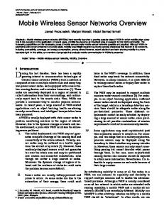
In this equitation, F is the magnitude of the electrostatic force on a charge Q1 due to the presence of a second charge Q2 , k is a constant value, and d is the distance between the two charges. The main difference is that while the electric particles generate a constant field of potential, the WSN nodes have to inform the others about their existence with radio messages. So a node can only calculate with node information it has already received. And since other nodes can also move, their position can vary (a lot) between messages. During the tests, this approach became obsolete, because the motes tended to form a circle, rather than a grid, and by withdrawing the cohesion force, they sped away into the distance. There are other methods like [5], based on potential functions for mobile robot navigation. Since it was obvious that the motes need cohesion force, it could be included in the force that originally retracts the motes. We developed a new one. So the function of the potential field became a Mexican hat function, with a little modification. Since the zero point of the function was important, the “hat” was smoothed at the appropriate point, to let the motes slow down before arriving at the equilibrium. To improve the speed of the algorithm, the function was approximated by a few polynomial functions and a hyperbole. The result function f (d ) is shown on Figure 1.
⎧ 1 − 2d 2 ; 0 ≤ d < 0.5 ⎪ 2 ( ) 2 d − 1 ⎪ ; 0.5 ≤ d < 1 2 ⎪ − 8(d − 1) f (d )= ⎨ ; 1 ≤ d < 1.125 (2) 2 ⎪8(d − 1.25) − 0.25;1.25 ≤ d < 1.375 1 ⎪ ;1.375 ≤ d ⎪ − 512(d − 1.25)2 ⎩
(
)
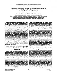
The figure 2. shows the area each mote generates around itself. It shows the absolute value of the force, that can be either positive or negative. Positive force means distraction, negative means attraction. The motes first pass the “wall” at the perimeter (since that force drives them closer) but then find a “mount” of potential at the front, what retracts them, and a “potential wall” at their back what still makes them move closer. Between the two forces there's a small circle of zero force, a “potential pit”, where the motes acquire the smallest potential (zero).
Figure 2. The modified Mexican hat function.
The distances between the mobile sensor and the other sensors are given by:
di, j =
(x
− x j ) − ( yi − y j ) . 2
i
2
(3)
Each sensor node exerts a virtual repulsive force toward the mobile sensor node. The resultant virtual forces are given by: N x − x r r N y − yj r j Fj = ∑ i f (d i , j )⋅ ex +∑ i f (d i , j )⋅ e y di, j di, j i =1 i =1 i≠ j
i≠ j
r
(4)
r
for each mobile nodes, where e x and e y are unit vectors Figure 1. Behavior of the field as a function of distance.
The optimal distance and the force can be easily attributed by simple function transformations. This function uses the following polynomials to approximate the modified Mexican hat function.
of a Cartesian coordinate system. The motion of the mobile node is given by dynamics:
r &pr& = F − k ⋅ pr& i i i where k is the damping factor.
(5)
IV.
SIMULATOR
The developer in most of the cases cannot test his/her software in the real world, at least not as many times as the development requires. Even the lack of devices, the lack of area or the slave-work of reprogramming all of the motes can slower the development. So it is important to test the software in the virtual world before applying it to the real world. The TinyOS system has a built-in simulator library [6], that can be accessed by adding target sim to the make compile line. This creates the PC byte code of the NesC program (object file), linked in a shared library with the simulator core. This data then can be accessed by linking this to an ordinary Python or C++ application and using the Tossim classes. This simulator library is event-driven, it contains a quite good controlling system and well-formed gain based radio model. This means describing the topology by giving each pair of motes the gain with which they hear each other from on direction and from the other direction, enabling asymmetric links. It also simulates noise, which is described by giving statistical noise level data. The developing environment is a Cygwin with TinyOS installed, along with the suitable NesC compilers for the AVR and MSP420 architectures. The testing is mostly done on this system also using the Cygwin/X module and WindowMaker environments. A. Basic structure The simulator consists of three parts: the driver code, the visualization engine and the core. This shows the commonly used MVC (Model View Control) architecture. The compiling takes two turns: first, the driver code is compiled, along with the NesC code and the Tossim library. It is done by using the ncc and gcc compilers. This creates C object files and a shared library. This can be tested in advance by using Python console. In the second phase, the core and the engine are compiled, linking the previously created modules and creating the application. The visualization engine uses the GLUT library, which is also required. The basic structure is described on the following graph: Driver I/O
command Top level operations
Reality
Driver modul Interrupt
event
Configuration TOSSIM modul
event
command
Simulator Queue event
VR modul
Event queue callback
User interface
Figure 3. Architecture of simulator.
The operation of the simulator is controlled from the user interface. Currently, this means starting and
suspending the simulator. After the signal to start, the simulator starts giving signals to the Tossim library in order to jump to the next event. An event means calling a previously registered callback function (the creation of the motes places boot events into the event queue), which means a jump into the NesC code. Usually, the callbacks call a NesC code in a VR module, and then it takes the usual call-signal route of events and commands. This piece of NesC code may also place new events into the event queue, and most of the time, it does. Each event has a precisely calculated time-stamp, with the precision on nanosecond scale. The visualization module works separate from the simulator itself. It calls for information whenever it needs to redraw the screen. During the tests, this visualization appeared to slow down the simulation, due to the insufficient performance of the Cygwin-X. So the simulator has been extended with logging capabilities, and a new visualization module has been created in Java, what lacks the 3D, but can show the full history of the simulation at once. This way, the testing cycle got lot faster and the debugging more easy. This intermediate logging is only a temporary solution. Since the ncc compiles the whole NesC code into a single dll (or .so, depending on the system), it is possible to call its functions from another program, written on a faster platform. Such a development is in progress. Under normal circumstances, the NesC code (displayed as top level operations) sends commands to a driver configuration, which redirects it to the consequent module. The module then sends signals through its I/O ports to operate the hardware. The hardware signals back through the I/O channels or the interrupts. This creates a NesC event in the driver module, which the configuration redirects to the top level. By changing the driver module reference in the configuration, the operation can also be changed. This is a general solution, mainly on hardware level. Many configurations have a different version for each architecture, since the machine level code and the port names are different. The correct version is decided by the first argument of the make command, the target platform. Since the modules are communicating through interfaces, it is not required to know, which architecture is used, which makes the language object oriented, implementing information hiding. The sim target uses gcc to link parts, instead of compiling it to the target architecture. This gives several possibilities. The main advantage is that the NesC code can call ordinary C functions. So by replacing the driver module with a version that calls C functions instead of sending messages on I/O ports, the NesC code can be linked into an ordinary C/C++ application. And here comes the driver code, which is also written in NesC and it only calls C functions to gather information about the virtual environment. This is the VR module, which communicates with a suitable C driver module. The C part of the driver stores meta-data for each mote, so the VR module can generate events based on the simulated environment.
The control is event-driven, which means that the code doesn't run continuously, but only steps to the next event each time called. The resolution is down to nanoseconds. This can be done because of the operation of the motes: they work, then they fall asleep until the next interrupt. The VR modules' main task is to schedule the interrupts, by inserting an event into the main event queue with the given simulation time and a callback function. The event can also hook other data required by the callback function. The event queue is common structure, a priority queue ordered by the time-stamp of occurrence. When ordered, the event queue takes the event with the lowest timestamp, and calls the associated function. Since the timer also operates through interrupts, it would be hard (impossible) to tell from the NesC code whether it is simulation or the real world. The visualization unit shows the user the status of the motes. Since it is generalized, it can be replaced easily. Currently two view modes are available, the potential field and the grid mode. The potential field view shows the sum of force that accelerates a mote placed in a given position. The grid view shows the position of the motes, with help of a grid on zero level. The module is written using OpenGL, so both views can be rotated in 3 dimensions. B. Operation In the initialization phase, the program creates a Simulator object, which will then control the operation of the system. The simulator object initializes 10 motes, placing them randomly on the screen, then initializes the noise model, by generating an artificial noise data and sending it to the core. Then the program creates the visualization component by creating the main window using GLUT. The window has different view modes, changing is possible with the '.' character. Initially the simulation is stopped. It can be started by pressing space-bar. Then the interface begins to periodically call the runNextEvent() function of the simulator, running the simulator. After every call, the simulator calculates the new position of the motes based on their speed (assuming that the speed does not change between events – the change would also be an event), then it creates the radio links between each node using: A = −20 log(1 + d ) (6) This ensures, that at 0 distance the gain would be 0 dB. This simulates the square decreasing of the radio signal level over distance. After the links have been calculated, the event is handled. On main disadvantage of this simulator is that the execution of a command takes only an instant in simulation time, therefore it does not happen that during the calculation of the new direction a radio signal is received. V.
TEST RESULTS
In this part the test results of the simulation are presented. The basic assumptions were quite ideal: all motes know their neighbors’ and their current position, each node has a strictly given radius, in which it can communicate with other motes. In every cycle, every node takes their neighbors' position, and calculates a direction
of motion using the previously described equitation. With only this, the nodes would spread across to a distance, where none of them are connected anymore. So in order to maintain consistence, the border of the area should act as a distraction force. By tuning the gain of these two forces, an optimal grid can be achieved. By these first results, the motes tend to form in closely perfect triangles and hexagons, because this way every mote is in equal distance from all of its neighbors. The shape of the groups tend to be less perfect near the edge of the area, deformed by the distraction force of the border. A simulation result is shown on the figure 4.
Figure 4. Optimal distribution of motes in a given area.
The next assumption was after the developing of the previously described simulator, so the realistic simulation of radio transfer was now possible. The algorithm is the following: first the mote locates itself, then it broadcasts its position and starts moving towards the center of the area. When it receives a radio message, it recalculates the speed based on the received position and its current position. This results in a very inaccurate topology, since the motes change their direction every time they get a new message, as an incoming radio message brought the effect of one billiard ball colliding another, generally referred as a Dirac impulse. This recognition gave the idea of storing the received positions. In the previous attempt, the radio messages only carried the position of the mote. In the next step, the message has been extended with the identifier and the speed of the mote. To run an inline simulation, the motes also got 6 memory slots to store the data of neighboring motes (the number is chosen after the result of the first attempt) and a timer which hits every 50 milliseconds. The preferred timer would run 1kHz, but many real-life results showed, that the timers are not accurate enough and the testing resulted that 200Hz is fair enough. When the timer hits, the mote updates the position of the stored motes and itself and then calculates its new speed. The stored data ages, when it reaches 5 seconds, data becomes invalid. This can be done because 5 seconds or more time without update means that the mote has moved too far to reach, so it is not a neighbor now. If an update is received, then the data is updated regardless of calculations and the aging timer restarts. When new data is received and there are no more slots, the data of the oldest slot is replaced, assuming that long time update means further mote. After the test,
this mainly appears in the first few seconds, when many motes are in close groups. Each mote broadcasts its position on a regular basis, so every mote has a frequent update. The problem is that while a mote waits for the radio channel to get clear enough, it also moves, so data becomes inaccurate. On the other hand, this waiting usually takes only a few milliseconds, so the data is still valid unless the motes move at a 50 m/s speed – which means the speed of a sports car on the highway. Longer waiting time only occurs in dense groups, but this kind of group rapidly dissolves, since the algorithm ensures that every mote which becomes aware that another mote is nearby, starts to race in the opposite direction. If they're close enough, they do it as fast as they can. Later the motes scatter enough not to disturb every other mote. VI.
CONCLUSION
The work has been pointing to a research result in which the WSN Technology has been combined with the nowadays popular mobile robot technology. By an optimization procedure the sensors were placed on the mobile robots in such a way that coverage was set to be optimal. To adjust the distance between the sensors, the method of potential fields has been used, and the system has been realized with a simulation. The application of the WSN simulator enabled the simulation of the behavior of the event-driven motes. During the simulations, the occurring errors have been repaired. In the end of a simulation, a sensor network was obtained
where the motes are in optimized distance from each other. The research will include further plans to improve the optimized algorithms for testing real sensors. The results of this work would gain importance if they were applied in the real world with real WSN and mobile robots. ACKNOWLEDGMENT This work was supported by Hungarian Development Agency under the TÁMOP-4.2.2/08/1/2008-0008 program. REFERENCES [1]
[2]
[3]
[4]
[5]
[6]
Radu Stoleru, Tian He, John A. Stankovic, David Luebke “A high-accuracy, low-cost localization system for wireless sensor networks”, Proceedings of the 3rd international conference on Embedded networked sensor systems, Pages: 13 - 26 , San Diego, California, 2005. Mustapha Boushaba, Abdelhakim Hafid, Abderrahim Benslimane “High accuracy localization method using AoA in sensor networks”, Computer Networks, Volume 53, Issue 18, 24 December 2009, Pages 3076-3088 Guoqiang Mao, Barış Fidan, Brian D.O. Anderson “Wireless sensor network localization techniques”, Computer Networks, Volume 51, Issue 10, 11 July 2007, Pages 2529-2553 Y. Koren, J. Borenstein “Potential Field Methods and Their Inherent Limitations for Mobile Robot Navigation”, Proceedings of the IEEE Conference on Robotics and Automation, Sacramento, California, April 7-12, 1991, pp. 1398-1404 S. S. Ge and Y. J. Cui “New Potential Functions for Mobile Robot Path Planning”, IEEE TRANSACTIONS ON ROBOTICS AND AUTOMATION, VOL. 16, NO. 5, OCTOBER 2000 TinyOS official documentation: http://docs.tinyos.net/index.php/Main_Page