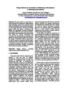
APPLYING SITUATED COGNITIVE ENGINEERING FOR PLATFORM AUTOMATION IN THE 21st CENTURY M. Grootjen1, Lt. Cdr., MSc.; M.A. Neerincx2 Prof. Dr.; N. Th. de Vries1 Capt., MSc.; N.A. Badon Ghijben1, MSc. 1 Royal Netherlands Navy, The Netherlands. 2 TNO Human Factors, The Netherlands.
ABSTRACT Technical crews on board of modern naval vessels need excellent support to maximize performance under a large variety of circumstances. The drive to save costs and reduce manning even increases the need for such support systems. Future Dutch naval ships include ship control centers which are manned depending on the status of ship and system. This new way of working not only sets new requirements for the technical system, but it also sets new requirements for the human operations and the corresponding operator capacities. This human aspect has been insufficiently addressed during all development and implementation phases of our current ships. ‘Old’ design and ship building methods, including the way industrial partners are involved, can’t answer these questions completely. This paper presents a new cognitive engineering method, consisting of three important parts. The first part is the analysis of operational demands, human factor knowledge and envisioned technology. In the second part requirements are specified for the three mentioned areas of the first stage, using scenarios, claims and core functions. The third part consists of reviewing and testing to refine the requirements in iterative loops. The method has been applied and shows how it can improve ship design for two future Dutch ships.
1. INTRODUCTION Naval ships contain sophisticated technology to perform information-driven tasks in dynamic environments, such as reconnaissance in literal waters. To adequately deal with the dynamic circumstances and complexity of information systems, technical crews on board of modern naval vessels need context-dependent task-directed support. The drive to save costs and reduce manning even increases the need for such intelligent support systems. Future Dutch naval ships include state of the art ship control centers which are manned depending on the status of ship and system. Under “nominal” sailing conditions, these centers will be empty and under “off-nominal” conditions (e.g. calamities, higher alert states, anomalies, or maintenance), a crew will be present tailored to the specific demands of the situation. Obviously, this way of working has an impact on the technical system support needs. For example, operators need mobile support to receive alarms when they are not in the control center. Besides technical consequences, this new way of working has a major effect on the human operator as well. The operational management on board changes and operators need other skills to deal with this new situation. Nowadays, we cope with problems to systematically address such human aspects in our ship design process. ‘Classical’ design and ship building methods, including the way industrial partners are involved, can’t consistently
take account of the human factors during all phases of system design. An important constraint is the difficulty to predict the joint operator-technology performance based on specifications only. The novelty of the technology and the uncertainty of human behavior in the usage scenarios, often cause requirements to change during development. Traditional waterfall design methods that aim at gathering a comprehensive and final set of consistent requirements before developing software are therefore not suited. To address the adequate deployment of human cognitive resources in the design process of support systems, [1] proposed a method for cognitive task load. [2] showed that this method can be applied for the design of unmanned ship control centers. Since then, this cognitive task load method was used and validated in multiple laboratory and real-world experiments. For example, in [3] several crews had to perform 8 scenarios with different load characteristics to analyze their responses in a high-fidelity simulator of the ship control centre of the Multipurpose frigate. Furthermore, we applied the cognitive task load method during evaluations at sea on board of the Air Defense and Command Frigates (ADCF) [4, 5]. Based on these experiences, we distinguish two questions for the future design of human-machine platform automation: 1. How can we build ships that address the human and technical factors, with their interrelationships, in such
a way that the performance in nominal and offnominal situations is adequate? 2. How can we reduce costs, reduce manning and keep the performance at an optimum at all time (i.e., for all these situations)? This paper presents application of a recent situated Cognitive Engineering (sCE) methodology, prescribing a systematic specification, refinement and validation process [6,7]. This methodology addresses operational demands, technological opportunities and constraints, and human factor theories and models to build up a first requirements baseline with the corresponding situated design knowledge. Using review methods, prototyping and simulation techniques, this paper shows how these knowledge and requirements are refined and validated in several iteration loops.
2. SITUATED COGNITIVE ENGINEERING The role of technology is changing in complex work environments with high levels of automation such as in the defense, space and medical domain. Machines are becoming part of joint cognitive systems with human and synthetic actors who collaborate for successful attainment of their joint operation objectives (e.g. [8]). ‘Classical’ Cognitive Engineering methods prescribe a humancentered iterative process of generation, evaluation and refinement of the system [9-11]. Currently, iterative design is common practice in many modern software development processes, and standards have been developed for such processes. For example, such an approach has been prescribed for office applications (e.g., ISO 13407 “Human-centered design processes for interactive systems”), defense systems (e.g., MIL-HDBK46855A “DoD Handbook-Human Engineering Program Process and Procedures”) and space systems (e.g., the ECSS-E-ST-10-11C “Space Engineering: Human Factors Engineering” standard of the European Cooperation for Space Standardization (ECSS)). In general, the iterative system evaluations and enhancements, involving future users and human factor experts, help to deal with changing requirements and will lower the above mentioned risks of human-technology mismatches considerably. 2.1 Analyzing: Understanding the work domain and context of operation. It is important to understand the work domain and context of operation well to develop effective and efficient cognitive systems. A variety of task analyses methods can be applied for this objective. Cognitive work analysis [12, 13] can be used as a method to analyze the affordances and constraints for complex sociotechnical systems in detail-like command and control defense systems [14]. In particular, the first phase of this work domain analysis identifies the constraints imposed on the workers by the
system. Constraints are either causal, determined by the laws of nature (physical), or intentional, based on the laws, standards, and/or ethics of people involved with the system and its environment (purposive). The system representation developed through work domain analysis is known as the abstraction-decomposition space, which represents constraints and affordances of the system’s operating environment in two hierarchies, the abstraction and decomposition hierarchies. The abstraction hierarchy represents means-ends relationships within the system environment. Elements at one level are the means to achieving elements at the next highest level, and the ends achieved by elements below. At the highest level, purposes like survivability are distinguished, and at the lowest level physical equipment and form are described like weapon and platform systems. The number of levels to distinguish depends on the objectives and domain of analysis (often five levels are distinguished). The decomposition hierarchy represents part-whole relationships, with elements at one level being parts of elements represented at the level above, and composed of elements represented at the level below. The number of decomposition elements can vary for the different sociotechnical systems. For example, [15] distinguish three parts: the ship, the target and the environment to connect the ship and target. Ecological interface design is part of the cognitive work analysis, applying the abstraction decomposition space to structure the user interfaces and to design the graphical representations and dialogue acts [16-18]. However, to create design solutions in an iterative way, the sCE methodology proposes to combine the analyses activities with scenario-based engineering activities as described below [19]. 2.2 Engineering: Generating, testing and refining the design. The cognitive work analysis approach of section 2.1 is most effective when used in conjunction with other analytic techniques [20]. The sCE methodology combines work and domain analyses with the more event-driven engineering approach of scenario-based design, claims analysis and evaluation [1, 19, 21, 22]. In this way, a sound requirements baseline can be built up with its design rationale. The analyses provide the needs and constraints of the cognitive system from an operational, a technical and a human factors perspective. These needs and constraints are tested, refined and validated in reviews, human-in-the-loop evaluations and simulations, possibly supported by game and virtual reality technology [23]. Figure 1 shows the general structure that consists of three components: the work domain and support analysis, the generation and maintenance of the requirements baseline with its rationale, and the review and refinement activities to improve and validate this requirements baseline.
Operations
Technology
Core Functions
Claims
Human Factors
Scenarios & Use Cases
Requirements Baseline Prototype Review Evaluate Comments
Refine
User Experience
Figure 1: The iterative process of situated Cognitive Engineering. In general, the cognitive engineering activities start with a work domain and support analysis, followed by a first requirements baseline specification and, subsequently, a series of refinement processes. It should be noted that during this process, new insights in the operational demands, human factors or technology can be acquired and used to further improve the requirements baseline. [7] provided a first sCE “best practice” of an adaptive automation component for track handling. This paper exemplifies the methodology and its envisioned impact for two system development processes of the Royal Netherlands Navy: The Joint Support Ship and the Concept Frigate 2020.
3.1 Joint Support Ship Operational: The number of onboard technical crew has been reduced to 50. Operational crew management has been altered to fit this purpose. The ship will operate without a permanently manned Ship Control Centre. Personnel have to be trained as technical specialists to do maintenance and they have to act adequately in case of calamities. Envisioned Technology: Large screen displays could support operators to maintain an adequate shared situational awareness. Furthermore, classical damage control boards could be replaced with a digital screen. Mobile networks, handhelds, and ultra mobile computers could support crew on location. A mobile communication network could improve communication over the ship. Mobile streaming video could provide required local information to the user. Human Factors: To use the technology, operators should be able to cope with the large amount information under the operational settings. Due to the increasing levels of automation, the risk increases that operators are out-ofthe-loop of the system control processes. Because there are no operators monitoring the systems in the ship control centre, situational awareness of running systems is low (i.e. awareness of the current status and the history or causes of this status). However, if a problem appears, operators have to build their situational awareness quickly to adequately take action, they should have “just in time awareness”. Other human factor issues are the interface support on mobile devices with its specific constraints due to size and context-of-use. Which information should be presented? In which way?
3. WORK DOMAIN AND SUPPORT ANALYSIS The work domain and support analysis identifies operational, human factors and technological demands that set specific objectives or constraints for the support of future naval missions. This section gives an example of such an analysis for the ship control centre of two future naval ships: The first is the Joint Support Ship (figure 2), which is currently in the contract phase and of which building should start in 2010. The second example is a Concept Frigate, of which the first plans are currently made (figure 3), and should sail around 2020. This example only serves to explain the method of figure 1. Obviously, it is not a complete description of the current status of the ship designs.
Figure 2: Joint Support Ship, planned to start building in 2010. 3.2 Concept Frigate 2020 Operational: This concept frigate 2020 will operate with 75% of the people (around 100) we are used have on current comparable ships. Engine and weapon engineers will be fully integrated into one group of technical engineers, with a general technical training. Furthermore, the crew size and composition is strongly dependent on the ship’s mission. Envisioned Technology: Further developments in telemaintenance and teletroubleshooting could provide support in case of problems. With use of this technology, specialists at shore could give advice to the engineers on
board and maintenance could be optimally planned in the harbors. Streaming video could supply environmental information to the specialist and could support conferences between the ship and shore office. Virtual reality and a virtual assistant could be of help in solving problems onboard. Developments in artificial intelligence, such as multi-agent systems and system health management methods, bring forth real or virtual machines that can act autonomously or in cooperation with the user. Adaptive support based on cognitive task load of the operator provides tailored support during calamities. Human Factors: In this case, the specialist at shore not only has to deal with autonomous processes, but also has to be able to build just in time awareness at a distance. Often, multiple layers of automation are present on the ship and he has to explain and collaborate with the engineer on board what to do to solve the problem. Effective communication, addressing non-verbal cues, building trust, and efficient coordination are important human factors issues to address in such a distributed adhoc team.
top-down (i.e. goal-directed, from a mission point of view) or bottom-up approach (i.e. event-driven, from a scenario point of view, see [1]): Step 1: Scenarios & use cases. Scenarios are coherent and situated stories about how operators undertake activities using the system in specific operational circumstances. In this step, scenarios are used to present and discuss the design rationale. Different levels of abstraction are useful in the specification of the requirements. Abstract scenarios can be achieved by talking to future operators, to understand what they do and what they want. With the collection of those stories, more concrete scenarios can be made, which are used for the generation of ideas and understanding of the requirements (e.g. the story of John, see below). Even more concrete are scenarios specified in an action sequence (figure 4), which can be used for prototyping and evaluation. In use cases the design is formalized by description of the interaction between operators and systems. Using a specific specification format, the general behavioral requirements for systems is described. According to our methodology, each use case should explicitly refer both to one or more requirements and to one or more claims. In addition, each claim and each requirement should be included in one or more use cases. Use cases and scenarios are very useful when discussing a not-yet-existing system with different stakeholders. With minor help most people are able to understand these design specifications. An example of a future scenario with our concept frigate will be given here, first in text, then more concrete in a flow chart (figure 4), and finally in a use case table (table 1).
Figure 3: Concept Frigate, planned to sail around 2020.
Scenario story of John: John is the corporal engineer on duty. He is responsible for the first actions in case of damage control emergencies and technical failures to keep damage to a minimum and alert the right people. Because this ship has an unmanned ship control centre, he is working in the engine room changing some oil filters. To be reachable for his colleagues, he’s wearing a mobile phone. Furthermore, emergency alarms will also be transferred to his phone if he’s on duty. While changing the oil filter from portside engine, an alarm appears on his phone: “high temperature radar room 3”. He accepts the alarm on his phone and starts walking to the nearest local operating position. Logged-in on this local operating position, another alarm appears “high bilge water pump room 2”. Realizing the seriousness of this emergency, John activates the technical emergency protocol, which alarms his colleague using his mobile phone, it tells him to go to the ship control centre. If John and his colleagues arrive in the ship control centre, the large screen displays show all relevant information to build just in time awareness. On one of the displays a procedure is shown. Important steps in this procedure are: (1) quickly build situational awareness of all systems involved in this emergency, (2) provide insight in possible actions to limit
In conclusion, reduced crew sizes and increased levels of automation ask for a design approach that addresses the adaptive nature of human and technology in a structural way. Iterative refinement cycles, which assess the requirements, their rationale and their implementation, will be needed to make adequate design decision throughout the development process.
4. GENERAL DESIGN RATIONALE AND REQUIREMENTS BASELINE The second component of the situated cognitive engineering methodology comprises establishment of the general design rationale, which consists of the core functions, claims, and scenarios & use cases (section 4.1), and the construction and maintenance of the functional requirements baseline (a structured list of all functional requirements, section 4.2). 4.1 The general design rationale. For the specification of the design rationale, we distinguish three steps. All three steps can be taken from a
damage to the ship (or check this in case automation executed these actions), (3) future consequences of those actions. After these steps, further analysis can be done and steps to repair the damage can be taken. John and his colleagues decide to ask advice of the specialists at shore. A video connection is established, and all data is transferred to the shore office. The specialist there can do a fast playback of the events, and build just in time awareness of the situation. Step 2: The core functions of the system are derived from the work domain and support analysis. For example, to better cope with autonomous processes, specific designed just in time awareness support can be proposed which brings about an adequate operator’s awareness if problems appear. Another core function can be the warning using mobile support (table 2).
Figure 4: Action sequence
Table 1: Brief example of high-level use case (based on [24]) Tag
General explanation
Description for usecase example
[UC_Nr] [UC_name] Goal
What is achieved by carrying out the use case.
Actor
Main human and synthetic actors.
Precondition
Contains the state of the system or user just before using All systems are working in autonomous mode. the functionality. The user has a limited awareness of most systems, and is working or relaxing somewhere on the ship.
Post condition
What is achieved using the functionality, describes the state of the system or user. Defines the event (e.g., time, alarm, …) when a user needs the functionality or how the system knows that the function needs to be carried out.
Trigger
Number and name used to link requirements to use case. Usecase 3: Problem solving with just in time awareness. System malfunction alarms that appear during unmanned operation of the ship control centre are adequately solved, because the operator gets adequate just in time awareness of the autonomous processes and corresponding system states. Technical engineer and the just in time awareness manager
The operator has awareness of the relevant autonomous processes and solved the problem. System malfunction alarm: high temperature radar room 3, high bilge water pump room 2.
Main Success Scenario
A top-to-bottom description of an easy to understand and See scenario story of John fairly typical scenario in which the actor’s goal is delivered.
Alternative Scenario
Other ways to achieve goal
... on his way to the local operation panel, John trips, hurts his head and loses consciousness for a couple of minutes. After a short time the system notices that the alarm is not accepted and reroutes it to another operator ...
Satisfies claim
List of claim-numbers that link to this use case
Claim 4.1, 4.2
Satisfies requirement
List of requirement-numbers that link to this use case
Requirements 1-4
Table 2: Example of core functions.
Table 4: Example of requirements for claims 4.1 and 4.2.
Core functions 1-5
Requirement
1. 2. 3. 4. 5.
1. If there is a malfunction in a system, automatically present: 1. System mimic(s) 2. Camera image of the system’s compartment 2. Systems that have a relation with the system that’s in alarm: 1. Should be easy accessible by one click 2. Camera images of these systems should be easy accessible by one click. 3. The system should propose possible solutions to solve the problem in procedural checklist formats. 4. The awareness support manager should show future consequences of offered solutions.
Provide mobile support Prevent automation surprises Ensure transparency Provide just in time awareness Prevent undesirable system behavior
Step 3: For each of the core functions of table 2, one or more testable claims on its operational effects have to be specified. These claims are formulated in terms of operational consequences, which can be evaluated in review processes or empirically tests with end-users (e.g. via standard methods for measuring human performance, effort and learning, [25]). Both positive and negative claims can be specified. An example for core function 4, provide just in time awareness, is shown in table 3. Table 3: Example of claims for core function 4. Core Function 4: Provide just in time awareness. 4.1 CLAIM Feature: If an alarm appears, all relevant information of the involved systems will automatically be presented on the overview screens. Results: If the operator walks into the ship control centre, he immediately builds up awareness of the autonomous systems (e.g., within 10 seconds, the operator knows which systems show failures and whether they are in a safe or unsafe state). 4.2 CLAIM Feature: Together with the relevant information of claim 4.1, possible solutions are shown with their consequences for future system states. Results: The operator is able to adequately select a proposed solution and to solve the problem, with an optimum awareness for future system states (to be assessed with the SAGAT method [26]).
4.2 Requirements baseline Based on the core functions and associated claims, requirements have to be specified (i.e., what the future system is supposed to do), taking notice of good requirement specification (e.g. [27]). Each requirement can be annotated with an indication of the importance relative to the functionality of the use case. The MoSCoW list [28] is often used to indicate the importance. MoSCoW stands for MUST have this, SHOULD have this if at all possible, COULD have this if it does not affect anything else, and WON’T have this time but WOULD like it in the future. Table 4 gives an example of some requirements for claims 4.1 and 4.2.
MoSCoW
M M
M S M
W
5. REFINEMENT PROCESSES The sCE methodology distinguishes two types of refinement and validation processes which should be used to confirm, refine or remove design specifications. First, domain, human factors and technical experts have to review the requirements baseline and its rationale, checking for consistency and validity. Second, simulation-based prototypes can be built for human-inthe-loop evaluations of the claims Besides this continuous process of the sCE methodology during the specification of requirements and rationale, another refinement process is of importance. At the end of the design phase, contracts are signed and the requirements and rationale are fixed and used as contractual agreements. However, this does not mean that for the next ship the design process should start from scrap. The design rationale is linked to the requirements and gives insight in the reasons why requirements were determined, which makes it excellent input for the next ship. Furthermore, evaluations of the final humanmachine system onboard are valuable input in new design processes. However, this doesn’t mean that the requirements and rationale of the existing ship should be duplicated and used as a starting point, this should be the input from the operational, technological and human factor analysis. This section will give a short overview of two ship control centre evaluations. Section 5.1 presents an assessment of operator load in the high fidelity trainer of the Multipurpose frigate [3], the second onboard of the ADCFs [4,5].
5.1 Operator load assessment Multipurpose frigate. In this experiment we used a method for cognitive task load to induce predetermined task load levels on the crew members of the ship control centre (figure 5). The cognitive task load method is based on a model that consists of three load factors: time occupied, task-set switching, and level of information processing. Application of the method resulted in eight scenarios for eight extremes of task load (i.e. low and high values for each load factor). These scenarios were performed by 13 teams in a high-fidelity control centre simulator of the Royal Netherlands Navy. For this study, one operator and one manager were selected from the full crew. The results showed that using this method, we could indicate underand overload situations with negative effects on operator performance.
Figure 5: Operator load assessment in the high fidelity trainer of the Multipurpose Frigate. One specific reason for decreased performance appeared to be the high amount of switches between different systems that the crew had to make, during high task load situations. Another reason for bad performance is the occurrence of under load. Long idle periods have a negative effect on performance. Both of these results can be used to change the design rationale, for example by implementing specific support rules for high task switching, and tools to keep the operator from under load, like adaptive task allocation.
5.2 Evaluation of automation levels ADCF. The ADCF is equipped with different levels of automation. In this evaluation, we tested whether the different levels of automation could accommodate possible negative load effects. Using the method for cognitive task load, three machinery breakdown scenarios with different task load characteristics were designed. These scenarios were performed by 12 teams on three sailing frigates, under three levels of automation. All sessions were recorded with special evaluation hard- and software, called the Observer [29] (figure 6). Results showed that the two highest levels of automation improved performance compared to the lowest one, especially under high task load. However, the intermediate automation level brought about additional needs for human-machine information exchange, which can reduce the task efficiency.
Figure 6: Evaluation of the levels of automation of the ADCF. The left bottom of the picture shows the screen which was used for video recording. Two important findings from this evaluation can be used in the design of new ships, or even in an upgrade of the current system. First of all, there was only little difference between the second and third level of automation. This study recommends deleting the second level, and adding a new level that has a higher level of automation. In this way a well balanced design of automation levels will be achieved. Second, recommendations are made to change the human-machine dialogue so task efficiency will be kept at an optimum.
6. CONCLUSION AND DISCUSSION 6.1 Conclusion For the development of future human-machine platform automation systems of the Royal Netherlands Navy, we distinguished two questions: 1. How can we build ships that address the human and technical factors, with their interrelationships, in such a way that the performance in nominal and offnominal situations is adequate? 2. How can we reduce costs, reduce manning and keep the performance at an optimum at all time (i.e., for all these situations)? This paper showed how the sCE methodology can be applied in the current ship development plans of the Royal Netherlands Navy, aiming at an incremental development of advanced technology and an adequate integration of the human and technical issues into the design processes. Furthermore, it showed how performance can be optimized in all conditions of the increased operation diversity of new naval missions. Using two short highlevel examples for the design of the Joint Support Ship and Concept Frigate 2020, we addressed operational demands, technological opportunities and constraints, and human factor theories and models to build up a first requirements baseline with the corresponding situated design knowledge. Using review methods, prototyping and simulation techniques, these knowledge and requirements are refined and validated in several iteration loops. In this way, the methodology follows an iterative human-centered development process corresponding to recent human-factors engineering methods and standards (e.g. ISO 13407 “Human-centered design processes for interactive systems”). An important element of the method is the traceability of requirement derivations with explicit references to the design rationale. A crucial core function is the support of just in time awareness. Therefore, a first overview was given concerning the claims on the operational effects and the functional requirements for the system. It is interesting to note that in several other domains with complex knowledge-intensive systems, there is the need to systematically address the adaptive nature of the human and the advanced technology during the system lifecycle. The sCE methodology was recently developed and applied in two research and development projects: for manned space missions [7], and for patient empowerment [30]. In both domains, it provided a practical, coherent and extendable requirements baseline for adaptive support that can be incrementally developed and implemented. Recently, a first application of the sCE methodology in a research and development project of the command centre of a Dutch Frigate was done. It provided a coherent and concise compilation of design knowledge for an adaptive automation module for track identification on naval ships [7].
6.2 Discussion As was already stated in section 5, the design rationale is an excellent way of securing important knowledge in the design of new ships. It can be seen as a database of knowledge which can be re-used many times, but it requires constant updating. However, after signing contracts with the industry, updating of requirements is limited or not possible at all. Taking the most important interactive human-machine aspects out of this agreement is a good alternative. Separate contracts with industrial partners to develop such systems in a more flexible iterative way ensure that end products live up to their expectations. Furthermore, some topics are not limited to one type of ship, but should be applied to all ships (e.g. style guides and design patterns for human-machine interaction). Developing this knowledge in separate processes and securing it in the design rationale provides an optimal and cost-effective design process. Although money needs to be invested in development projects, it will reduce the project management investments for each ship significantly. Obviously, working according to the sCE method asks for a tailored organizational business plan. An important part of the work is done on the design rationale before contracts are signed, but project management after the contracts are signed is an important aspect as well. How should requirements be met? Which measurements do we use to test this? In the naval domain our products often have to comply with civil standards. However, our operational management doesn’t correspond with the civil counterpart. These aspects need to be addressed in ongoing studies to optimize the design of platform automation.
REFERENCES [1]
[2]
[3]
[4]
[5]
[6]
[7]
[8]
[9]
[10]
[11]
[12]
[13]
[14]
Neerincx, M.A., Cognitive task load design: model, methods and examples, in Handbook of Cognitive Task Design, 2003, Lawrence Erlbaum Associates: Mahwah, NJ. p. 283-305. Neerincx, M.A., Dobbelsteen, G. J. H. van den, Grootjen, M., Veenendaal, J. van, Assessing cognitive load distributions for envisioned task allocations and support functions, in Thirteenth International Ship Control Systems Symposium (SCSS), 2003. Grootjen, M., M.A. Neerincx, and J.A. Veltman, Cognitive Task Load in a Naval Ship Control Centre: from identification to prediction, Ergonomics, 2006. 49(12-13): p. 1238-1264. Grootjen, M., Neerincx, M. A., Weert, J. C. M. van, Truong, K. P., Measuring Cognitive Task Load on a Naval Ship: Implications of a Real World Environment. in Proceedings of HCII/ACI 2007. 2007. Grootjen, M., T.E.d. Greef, and M.A. Neerincx, Effects of Level of Automation on Operator Task Load and Performance, Journal of Cognitive Engineering and Decision Making, in progress. Neerincx, M.A. & Lindenberg, J. (2008). Situated cognitive engineering for complex task environments. In: Schraagen, J.M.C., Militello, L., Ormerod, T., & Lipshitz, R. (Eds). Naturalistic Decision Making and Macrocognition (pp. 373-390). Aldershot, UK: Ashgate Publishing Limited. Neerincx, M.A., Te Brake, G.M., Van de Ven, J.G.M., Arciszewski, H.F.R., De Greef, T.E., and Lindenberg, J. (2008). Situated cognitive engineering: Developing adaptive track handling support for naval command and control centers. In: B. Patrick, C. Gilles and L. Philippe (Eds.). HCP-2008 - Third Internation Conference on Human-Centered Processes, pp. 3-20. Bretagne, France: TELECOM Bretagne ISBN: 978-2-908849-22-6. Hoc, J.-M. (2001). Towards a cognitive approach to human-machine cooperation in dynamic situations. International Journal of Human–Computer Studies, 54(4), 509–540. Hollnagel, E., and Woods, D. D. (1983). Cognitive systems engineering: New wine in new bottles. International Journal of Man–Machine Studies, 18, 583– 600. Norman, D. A. (1986). Cognitive engineering. In D. A. Norman, and S. W. Draper (Eds) User-Centered System Design: New perspectives on human–computer interaction. (pp.31-62). Hillsdale, NJ: Lawrence Erlbaum Associates. Rasmussen, J. (1986). Information processing and human– machine interaction: an approach to cognitive engineering. Amsterdam, Elsevier. Vicente, KJ (1999). Cognitive Work Analysis: Toward Safe, Productive, and Healthy Computer Based Work, Lawrence Erlbaum Associates, London. Naikar, N & Sanderson, P.M. (2001). Evaluating Design Proposals for Complex Systems with Work Domain Analysis, Human Factors, 43(4), 529-542. C.M. Burns, D.J. Bryant, and B.A. Chalmers (2005). Boundary, Purpose, and Values in Work Domain Model: Models of Naval Command and Control, IEEE Transactions on Systems, Man and Cybernetics Part A, pp. 603-616.
[15] C. M. Burns, D.J. Bryant and B.A. Chalmers (2000). A Work Domain Model for Shipboard Command and Control, Proc. IEEE International Conference on Systems, Man, and Cybernetics, pp. 2228-2233, [16] Burns, C.M., & Hajdukiewicz, J.R. (2004). Ecological Interface Design. Boca Raton, FL: CRC Press. [17] Witt, O., et al., eds. Ecological Interface Design fuer Konditionierungsparameter von Fregatten. Ergonomie und Mensch-Maschine-Systeme, ed. L. Schmidt, C.M. Schlick, and J. Grosche. 2008, Springer. 161-178. [18] Groskamp, P.A. van Paassen, M.M. Mulder, M. (2005). Interface design for engagement planning in anti-air warfare. EEE International Conference on Systems, Man and Cybernetics 2005, Volume: 1, 311- 316. [19] Neerincx, M.A. Bos, A., Olmedo-Soler, A. Brauer, U. Breebaart, L., Smets, N., Lindenberg, J., Grant, T., Wolff, M. (2008). The Mission Execution Crew Assistant: Improving Human-Machine Team Resilience for Long Duration Missions. Proceedings of the 59th International Astronautical Congress (IAC2008), Paris, France: IAF. DVD: ISSN 1995-6258. [20] Baker, C., Naikar, N. and Neerincx, M.A. (2008). Engineering planetary exploration systems: integrating novel technologies and the human element using work domain analysis. Proceedings of the 59th International Astronautical Congress (IAC2008), Paris, France: IAF. DVD: ISSN 1995-6258. [21] Rosson, M. B. and Carroll, J. M. (2001). Usability engineering: Scenario-based development of humancomputer interaction. San Francisco, CA: Morgan Kaufman. [22] McCrickard, D.S. and Chewar, C.M. (2006). Designing Attention-Centric Notification Systems: Five HCI Challenges. In: J. Chris Forsythe, Michael L. Bernard, and Timothy E. Goldsmith (Eds.). Cognitive Systems: Human Cognitive Models in Systems Design, pp. 67-89. Lawrence Earlbaum. [23] Smets, N.J.J.M., Abbing, M.S., Neerincx, M.A., Lindenberg, J, and van Oostendorp, H. (2008), Gamebased evaluation of personalized support for astronauts in long duration missions. Proceedings of the 59th International Astronautical Congress (IAC2008), Paris, France: IAF. DVD: ISSN 1995-6258. [24] Cockburn, A. (2001). Writing Effective Use Cases, Addison-Wesley, ISBN 0201702258 [25] Salvendy, G. (Editor): Handbook of Human Factors and Ergonomics (3rd edition), New York: John Wiley and Sons, 2006. [26] Endsley, M.R. (1995). Measurement of situation awareness in dynamic systems, Human Factors, 37(1), 6584. [27] IEEE Std 830-1998. IEEE Recommended Practice for Software Requirements Specifications. ISBN: 0-73810332-2 [28] Clegg, Dai; Barker, Richard (2004). Case Method FastTrack: A RAD Approach. Addison-Wesley. ISBN 9780201624328. [29] Noldus, Observer XT. 2006. [30] Blanson Henkemans, O.A., van der Boog, P.J.M., Lindenberg, J., van der Mast, C.A.P.G.,. Neerincx, M.A., and Zwetsloot-Schonk, B.J.H.M. (forthcoming). An Online Lifestyle Diary with Persuasive Computer Assistant for Support of Self-Management. Technology & Health Care.
BIOGRAPHY AND CONTACT INFORMATION Marc Grootjen is a Lieutenant Commander with the Royal Netherlands Navy doing his Ph.D. degree at TNO Defence, Security and Safety and the Technical University of Delft, on the subject “Adaptive Interfaces for operational Support”. He graduated the Naval Academy in 2000 as a Technical officer and received his M.Sc. in Mechanical Engineering at the Technical University of Delft in 2002. Current research focuses on the development of a system and interface that adapts to the momentary state of the operator. Marc Grootjen can be reached at
[email protected] Mark Neerincx is head of the Intelligent Interface group at TNO Human Factors, and professor in Human-Machine Interaction (HMI) at the Delft University of Technology. His research has been focusing on (1) a cognitive task load model for task allocation and adaptive interfaces, (2) models of human-machine partnership for attuning assistance to the individual user and momentary usage context, (3) cognitive engineering methods and tools, and (4) a diverse set of usability “best practices”. Mark Neerincx can be reached at
[email protected] Nine Badon Ghijben studied Industrial Design Engineering at the Technical University of Delft and received her Master of Science degree in 2004. In 2005 she joined the Royal Netherlands Navy as a lieutenant. Since 2006 she works as a civilian at the at the Defence Materiel Organisation. Currently she works as a Senior System Engineer and Project Engineer mainly on the platform management system of the upcoming Dutch Patrol Vessels. Nine Badon Ghijben can be reached at:
[email protected] Presented at the Fourteenth International Ship Control Systems Symposium (SCSS) in Ottawa, Canada, on 21-23 September 2009.
Nico de Vries is head of the department naval platform systems and automation. Nico de Vries can be reached at
[email protected]