area of design automation like integration of different tailor made software developed ... computer programming language and CREO Parametric as modeling ...
IJRET: International Journal of Research in Engineering and Technology
eISSN: 2319-1163 | pISSN: 2321-7308
DESIGN OF A GRAPHICAL USER INTERFACE FOR DESIGN AUTOMATION Umesh A. Bedse1, Laukik P. Raut2 1
M.Tech Student, Department of Mechanical Engineering, GHRCE Nagpur, Maharashtra, India Assistant Professor, Department of Mechanical Engineering, GHRCE Nagpur, Maharashtra, India
2
Abstract In research and development field, many research efforts have been made to save the overall time of product design and development of any product. As we know that design phase has a lot of potential where overall time can be saved. Hence, design automation has been the best concept came into picture which involves integration of different software like product design software developed, modeling software and analysis software. It has been observed that many researchers are taking efforts in the area of design automation like integration of different tailor made software developed using different computer programming languages like Visual Basic, Java, C++ with different CAD software like Pro/E, CREO Parametric, CATIA, SolidWorks .But it is observed that Visual Basic is having some better advantages over others like it will give dot frame work for design of product input base as well as it can be easily interface with intermediate software like Microsoft excel which provides an input to other modeling or analysis software and among all available parametric modeling software CREO is widely used in industries because it has best parameterization quality. In this paper, integration of product design software developed using Visual Basic as computer programming language and CREO Parametric as modeling software by taking the case study of design of CI Engine parts has been done to validate the concept. Simulation of CI Engine is added in developed GUI which gives results of pressure, temperature, volume at each crank angle of crankshaft in the form of graphs and maximum value of pressure and temperature got are being used for structural and thermal analysis of major components.
Keywords: CAD, GUI, Simulation, CREO, Visual Basic. ---------------------------------------------------------------------***--------------------------------------------------------------------1. INTRODUCTION If we look at the worldwide scenario, every industry is striving to do automation in every department to save overall time, labor cost, to increase productivity and overall profit. Maximum automation has been achieved in most of the industries because of the inventions of advanced machinery; robots are replacing labors right from loading and unloading of a job in the machine to the dispatch of the final finished product. Still these industries are struggling to save the time of design phase. It has been observed that design phase has so much potential to save the overall time of product design and development phase. Hence, nowadays inventors are concentrating on the automation in the design phase. To save overall time, automation in the design phase is the best alternative. It has been observed that there are so many 3D CAD modeling software have been invented to get the better visualization of product to be manufactured and because of these software, conversion of the 3D model to 2D manufacturing drawings has become very easy. There is so much scope to save time in the design phase. But all these creations of 3D model require highly experienced and skilled peoples to get work done in less time. The best way is to do automation in design and modeling phase which is very easy and cheap way to save overall time. Any industry can implement this type of automation; only thing is that
this automation requires experienced and highly skilled people having the complete knowledge of design of that particular product. The design of any product is generally done based on the past experience of the designer because it is done on trial and error basis. Maximum engineering hours gets wasted in formulating and understanding the existing available design. Hence, it is necessary to make standard design process to satisfy user requirements. To do this type of automation, one simple and the best way is the integration of different software of various stages of product design and development phase like product design software, modeling software, and analysis software. It has been seen that nowadays there are so many CAD and analysis software like CATIA, CREO, Pro/E, HyperMesh, ANSYS, Unigraphics NX etc available in the market but specific product design software is not available. So, it is required to develop product design software in the form of a Graphical User Interface (GUI). To develop a GUI, knowledge of computer programming language is necessary. There are many computer programming languages available like C, C++, C#, Visual Basic, JAVA, Python etc., but among all these languages Visual Basic is the best option because it is very easy to understand and having strong and best frame work(Jadeja, Bhuptani, & Gujarat, 2014). In this paper, a GUI has been developed using Visual Basic as computer programming language due to its advantages over
_______________________________________________________________________________________________ Volume: 05 Issue: 09 | Sep-2016, Available @ http://ijret.esatjournals.org
175
IJRET: International Journal of Research in Engineering and Technology
others. During the literature survey, it has been observed that among all above-stated modeling software, CREO Parametric has been the best option and this is the software which is adopted by most of the industries because of its advantages over others like it has strong and best parameterization quality which is very important for design and modeling automation. To analyze the design is correct or not analysis of product designed is very important and in this paper analysis of important components is done in ANSYS Workbench 14.5 analysis software. Hence, in this paper integration of a GUI or tailor-made software developed using Visual Basic as computer programming language and CREO as modeling software for design. The designer gets output within a second in terms of design parameters in the form of excel spreadsheet from
eISSN: 2319-1163 | pISSN: 2321-7308
tailor-made software which will be the only media of integration with available CAD package. Any number of formulae for design calculations, any number of buttons and check list box for the selection of available standard values from stored database like material properties, all these can be added which depends on designer and developer of that software. The developer has complete freedom to go in any depth of advancements to make that particular product design software. With the help of development of this product design software, huge repetitive calculations get solved within a second which avoids hectic manual work of a designer. Hence, the designer will get extra time to think for better innovations.
2. METHODOLOGY
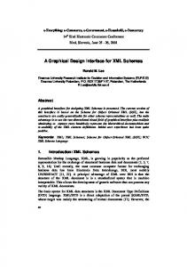
Fig 1 Methodology
_______________________________________________________________________________________________ Volume: 05 Issue: 09 | Sep-2016, Available @ http://ijret.esatjournals.org
176
IJRET: International Journal of Research in Engineering and Technology
eISSN: 2319-1163 | pISSN: 2321-7308
In above-shown flow chart, three phases have shown, first is product design phase, the second is integration phase and the third one is a modeling phase. Integration of all these phases results in design automation.
Axial thickness of piston ring (mm) Thickness of piston head (mm) Diameter of crank pin (mm) Length of crank pin (mm)
In the first phase that is product design phase, with the help of computer programming language and standard design relations development of a GUI has been done by using tool available in tools like buttons, text box, list box, combo box, pointer etc. This development of a GUI completely depends on designer which will be useful to satisfy user requirements. The user will enter the input variables and after click on design button, coding behind that button will run and give the output result within a second in terms of required design parameters in pre-decided text boxes. After getting all design output variables, these results will be put together in excel spreadsheet in specified cells and this excel spreadsheet will be the only media to integrate with intermediate software to do the design automation. After assigning all the relations from relations tool in modeling software to the dimensions of a 3D CAD model to get modified, the user has to update this excel spreadsheet only to get the modified model. The second phase that is integration phase is nothing but the integration of excel spreadsheet with the intermediate modeling software. The third phase is nothing but the modeling phase, in which user first do the modeling of parts or import the already stored model from the database and with the help of excel analysis menu user can get the regenerated model within second by using this integration concept. Once the user has assigned output design variables to the model, after that whenever the user has to do modifications in the model, there will be no need of remodeling, the user just have to edit this excel spreadsheet as per the required modifications and within a second user will get modified model. If the regenerated model is not satisfactory, then again open the excel sheet and edit the dimensions from cells and regenerate the model, repeat the same procedure till the user will get the satisfactory model. In this way, design automation gets done.
3. CASE STUDY
To validate this methodology, in this paper case study of the design of IC engine parts is taken. For this design, required important input and output variables are specified below. Complete GUI is developed to obtain these output variables. Input Variables:Brake Power (KW) Speed (rpm) Mean effective pressure (MPa) Number of strokes Explosion Pressure (MPa) Number of piston rings Output Variables:Bore (mm) Length or Stroke (mm) Diameter of piston (mm) Radial thickness of piston ring (mm)
To validate this design automation concept, in this work case study of the design of IC Engine parts has been taken. We knew that there are so many numbers of mechanical components present in complete IC engine and design of these components is very time-consuming. Hence, it has been decided that design of IC Engine components will be the best case study to fulfill all the objectives of this work. During literature survey, it has been observed that many researchers have done work in this area by taking so many different case studies and by using different computer programming languages and modeling software to achieve their goal of work but they have taken simple components or assemblies as a case study. Main reason behind this case study of IC engine is that assembly of complete IC engine has many numbers of parts and hence it will be helpful to achieve design automation in such big assembly. But for the initial stage to achieve this automation, design of only major components of IC Engine has been taken into consideration like the design of crankshaft, piston and cylinder. Simulation part is also added in the developed GUI to see the pressure, volume and temperature variation at each crank angle of crank shaft of CI Engine during compression, combustion and exhaust stroke in terms of graphs.
4. PROBLEM DEFINITION
D models of parts of the machine and its manufacturing drawing which also requires skill. [3] Integration of design and modeling phase of the simple component is done till now but the integration of design, modelling and analysis phase is not done yet. Designer waFor design and modeling of the product, the time required is generally 60-70% of the overall time of the product development. Hence, no scope of innovations in existing designs is possible [1] Nowadays design process is currently done on past experience; experienced persons are required every time for designing. This involves selection of standard parts and materials which require complete knowledge of product design. [2] After design calculations are done, it takes much time to make CAstes the most of the overall time in understanding the existing designs and struggles with the challenges associated with the modifications in existing design and the improvements in those designs. [4] Repetitive manual calculations take much time and it is really tedious work for designers, hence, 100% accuracy is not guaranteed with the manual procedure of design.
_______________________________________________________________________________________________ Volume: 05 Issue: 09 | Sep-2016, Available @ http://ijret.esatjournals.org
177
IJRET: International Journal of Research in Engineering and Technology
eISSN: 2319-1163 | pISSN: 2321-7308
5. IMPLEMENTATION 5.1 Development of a Graphical User Interface
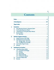
Fig 2 Developed GUI In this chapter, a GUI is developed using Visual Basic computer programming language in Visual Studio 2010. To develop this above shown GUI in Fig.2, a case study of the design of IC engine parts has been taken which contains the design of piston, the design of crankshaft and design of cylinder. Text boxes used for input variables are shown above design button in every part of design in a GUI, and text boxes of output variables or design parameters are shown below design button. Code containing design calculations of each part is run on the click event of that particular design button. To make it more user-friendly, the pointer is added to a particular text box to give suggestion about standard value as shown for text box of cylinder wall pressure in the design of piston section so the user should not open the design data book to see those standard values and ultimately time get saved. With the help of this GUI, repetitive calculations are done in few seconds which saves much time.
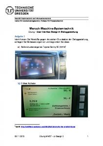
Max. Pressure = 63 bar
SIMULATION One more important part added in this software is a simulation of CI engine. With this simulation, pressure, temperature, and volume are obtained in the form of graphs at each crank angle of crankshaft so the user can visualize the variation of pressure, temperature and volume with respect to crank rotation through each degree of angle. To achieve this simulation huge coding is there.
Fig 3 Graph of Pressure Vs Crank Angle
_______________________________________________________________________________________________ Volume: 05 Issue: 09 | Sep-2016, Available @ http://ijret.esatjournals.org
178
IJRET: International Journal of Research in Engineering and Technology
eISSN: 2319-1163 | pISSN: 2321-7308
Fig 6 Excel Spreadsheet
5.3 Modeling Phase Fig 4 Graph of Volume Vs Crank Angle
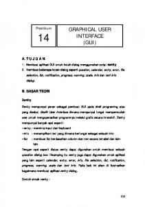
Max. Temp = 2575 K
Fig 7 Assembly model of IC engine
Fig 5 Graph of Temperature Vs Crank Angle
5.2 Generation of Excel Spreadsheet Generation of excel spreadsheet is the most important step in this project because to do the integration of product design and modeling software excel spreadsheet is the only available media. So, this excel sheet must contain all required output variables to be used for integration. Below excel sheet shown in Fig. 6 contains all the output variables used as important design parameters of the cylinder, piston and crankshaft of IC engine.
Here, assembly modelling of IC Engine has been done using CREO Parametric 2.0 as modelling software. This assembly contains parts like cylinder block with fins, piston, connecting rod and crankshaft as shown in Fig.7. For design automation, excel analysis has to be done for each part separately by integrating excel sheet and after all, parts get modified separately finally assembly gets regenerated automatically.
5.4 Integration of Excel spreadsheet with CREO Parametric Integration of excel spreadsheet and CREO is the only way to here achieve design automation because excel file is the only media to integrate product design and modelling software. In modelling software like CREO, Pro/E, CATIA etc., there is one menu available that is excel analysis through which this design automation happens. The user need to load excel
_______________________________________________________________________________________________ Volume: 05 Issue: 09 | Sep-2016, Available @ http://ijret.esatjournals.org
179
IJRET: International Journal of Research in Engineering and Technology
file produced from a GUI developed using Visual Basic computer programming language and assign values of output variables of a particular design to that model through relations tool.
eISSN: 2319-1163 | pISSN: 2321-7308
analysis, steps are shown in above Fig. 9 by red arrows and numbers. The first step is go to excel analysis menu in analysis option available in the menu bar, one window will appear on screen as shown in Fig.9. In that window, to load excel spreadsheet go to ‘Load File’ icon and browse the excel file. Excel file will appear on screen as shown above. Select dimensions from excel file to be assign for the modification of the model. Here the first column is selected which contain output design parameters of the design of cylinder block. Then click on ‘output cells’ button of excel analysis window shown by number 3 in circle, it will get values from excel cells to CREO. Next step is to click on Compute button shown by number 4, values will come to results list as shown. The final step for excel analysis is go to Add Feature as shown by number 5 and type the name of the excel file there and finally close the window. This completes the excel analysis step for regeneration of cylinder block.
Fig 8 Cylinder Block Part model of the cylinder block has open in new window separately from assembly model. Now, the user wants to modify this part model of the cylinder block. To avoid manual modification, excel analysis option is selected as shown in Fig. 9.
Fig 10 Dimensions to be Modify These are the dimensions of cylinder block before modification. The user has to modify these dimensions to get updated model.
Fig 9 Excel Analysis There are some important steps to be followed by the user at the first attempt of modification after that user just have to modify dimensions in a particular cell of excel sheet and there is no need to do excel analysis again. To do excel Fig 11 Relation Tools
_______________________________________________________________________________________________ Volume: 05 Issue: 09 | Sep-2016, Available @ http://ijret.esatjournals.org
180
IJRET: International Journal of Research in Engineering and Technology
eISSN: 2319-1163 | pISSN: 2321-7308
After completing excel analysis and relations tool steps, go to regenerate model menu shown in fig.12 and click on the regenerate icon to get a regenerated model of the cylinder block. This completes the first attempt of regeneration as per the output variables got from product design software in the form of excel sheet. Now, hereafter whenever the user wants to modify this cylinder model, there is no need to do all the above mentioned 13 steps. The user just has to update the dimensions in excel sheet and do the following steps shown in Fig. 13.
Now, the next step is to add relations using relations tool available in tools menu shown by number 6 in Fig.11, after clicking on ‘relations’ menu one window will open as shown named ‘Relations’. Now, click on the model of the cylinder block, dimensions will appear in blue color with letter ‘d’ followed by one number which is different for each dimension. For bore of cylinder ‘d1’ is appeared. Next step is go to option ‘Insert Parameter from list’ icon shown by round bracket numbered by 7. A new window will open named as ‘select parameter’ as shown in fig.11. In that window go to ‘Look In’ list box and there click on ‘featured’ object type shown by number 8. Now, go to excel sheet listed in the model tree of CREO appearing on lefthand side is shown by number 10. Dimensions selected during excel analysis will listed there. To assign relation for the bore of the cylinder, bore dimension is shown by ‘d1’ and present in (2, 1) cell of excel sheet. After finishing 11 th step, click on ‘insert selected’ button that is step 12. Likewise, repeat the same procedure for all preselected dimension of the cylinder. This completes the relations tool step for cylinder block.
Fig 13 Update Excel sheet to re-modify model To update the model again as per user requirements, go to excel sheet available in a model tree on left-hand side of CREO software screen. Right click on that sheet and click on edit definition icon there. One window will open named as analysis as shown in Fig.13. Then click on ‘next’ button from that analysis window, excel sheet will open as shown, now edit the required dimensions to be modified in excel sheet, save the sheet and then click the button ‘Compute’ from excel analysis window and close the excel analysis window. The last step is just to click on green tick available on analysis window was shown and finally, go to the model menu and regenerate the model. Within one click model gets modified as per the user requirement.
Fig 12 Regeneration of Model Fig 14 Regenerated Assembly
_______________________________________________________________________________________________ Volume: 05 Issue: 09 | Sep-2016, Available @ http://ijret.esatjournals.org
181
IJRET: International Journal of Research in Engineering and Technology
eISSN: 2319-1163 | pISSN: 2321-7308
The final step is go to assembly and click on a regenerate model to get regenerated assembly as shown in Fig 14.
5.5 Analysis Phase Analysis of cylinder block and piston is done in ANSYS Workbench 14.5. For this analysis, modeling of IC engine is done in CREO Parametric as mentioned above. User just has to import that model in suitable format like STEP file format to complete the analysis phase. In this project, analysis like steady state thermal analysis and static structural analysis is done on two main components which are cylinder block and piston because these two main components actually goes under all chemical reaction of fuel and ultimately goes through highest temperature and pressure because of combustion of fuel during combustion stroke. Hence it is necessary to do thermal and structural analysis of these components to get the best result. For steady state thermal analysis is to be done it requires maximum temperature value to do the analysis and with the help of developed GUI, user gets that value of maximum temperature through simulation graph of crank angle Vs temperature as shown in Fig. 5. In this case temperature consider inside cylinder block is 2575 K which is got from graph as shown and convective heat transfer with stagnant air medium is considered for fins and results of temperature is shown below.
Fig 16 Steady State Thermal Analysis of Piston Also to observe the deformation of piston due to high pressure generated on piston head, it is necessary to do static structural analysis of piston. For this analysis user has to input maximum pressure value applied on piston head, user can get this value of pressure from simulation graph of crank angle Vs pressure generated using developed GUI as shown in Fig 3. In this case, maximum pressure generated value is near about 63 bar and analysis results obtained are shown in below Fig 17
Fig 17 Static Structural Analysis of Piston Fig 15 Steady State Thermal Analysis of Cylinder Block Same steady state thermal analysis is done for piston also by considering same temperature and convective heat transfer and results of temperature of piston is shown in fig 16.
If user is not satisfied with the analysis results, he just have to enter the different input variables in a GUI and according to output variables designer just have to modify excel sheet to get modified part model. As input variables get change according to that values of temperature and pressure obtained from simulation graphs will get change. Then user has to import modified model in ANSYS Workbench and enter obtained values of temperature and pressure for required analysis. In this way user has to repeat this process till the satisfied results of analysis he will get.
_______________________________________________________________________________________________ Volume: 05 Issue: 09 | Sep-2016, Available @ http://ijret.esatjournals.org
182
IJRET: International Journal of Research in Engineering and Technology
6. CONCLUSION
With the help of this integration of tailor made software developed using Visual Basic as computer programming language and CREO as modeling software, up to 95% of the time has been saved as compared to the time required for conventional design and modeling process. This integration is the best way to avoid repetitive tedious work of engineers and hence, engineers can possibly do the innovations in their respective field. Engineering hours got saved with this concept. There is no need to have highly skilled persons for design and modeling in industry, a person can import the existing models from the available database and will modify that model as per the user requirement in some cases. As we already discussed that design and modeling phase has much potential where time can be saved by the implementation of automation and here the results are in front of us. This integration will surely play a very helpful role for industries. To achieve this design automation, Visual Basic is the best option for computer programming language due to its advantages over other languages as mentioned above and CREO Parametric is best option for modeling software because of its strong parameterization quality.
eISSN: 2319-1163 | pISSN: 2321-7308
Engineering Sciences & Research Technology, vol. 3(4), pp. 4089-4095, April 2014 [2] Prof. U. M. Nimbalkar, Akshaykumar V. Kadam, "Automatic Assembly Modeling for Product Variants using Parametric Modeling Concept," International Journal of Engineering Research & Technology, vol. 4, no. 4, pp. 79-89, April 2015 [3] A.S.Rao, Abhishek C. Lad, "Design and Drawing Automation Using Solid Works Application Programming Interface," International Journal of Emerging Engineering Research and Technology, vol. 2, no. 7, pp. 157-167, October 2014 [4] S. Sundar ,Yaswanth Peddireddy, "Automated Design and Modelling of Knuckle Joint," International Journal for Scientific Research & Development, vol. 3, no. 2, pp. 235-239, 2015
7. FUTURE SCOPE The work presented here consist of design and development of a GUI using Visual Basic and modeling using CREO modeling software to achieve design automation for the case study of design and modeling of IC engine. Also the analysis of some important components is done in ANSYS Workbench 14.5. Yet, the concept presented in this paper could be further modified and extended with following considerations. This concept can be implemented using different programming languages and different modeling software to achieve best results as per the designer convenience. This system can be used to achieve automation in analysis phase to get more advancement in product design and development phase. Present work shows, design automation of IC Engine, instead of that designer can take any product design as per their industry requirement and according to that product, development of a GUI and modeling has to be done. In a GUI only, advance simulation of components can be done in the form of graphs to achieve better results. This complete system can be further integrated with the CAE packages available.
REFERENCES [1] J., Bhuptani, K. M., & Gujarat, R. Jadeja, "Developing a GUI based Design Software in VB Environment to Integrate with CREO for Design and Modeling using Case Study of Coupling," International Journal of
_______________________________________________________________________________________________ Volume: 05 Issue: 09 | Sep-2016, Available @ http://ijret.esatjournals.org
183