Optimizing Device Size for Soft Error Resilience in Sub-Micron Logic Circuits Warin Sootkaneung, Kewal K. Saluja Department of Electrical and Computer Engineering, University of Wisconsin-Madison Madison, WI 53706, USA E-mail:
[email protected],
[email protected] Abstract As technology nodes are being scaled down, soft errors induced by particle strikes are becoming a troublesome reliability issue in logic circuits. Various sizing techniques commonly used to reduce soft error rate in the past are expensive in terms of area, performance, and energy consumption. These methods require changes to adapt to sub-micron technologies. This study introduces two novel sizing methods that selectively upsize transistor networks of a circuit. Our first proposed methodology formulates the soft error rate minimization as a mathematical optimization problem and searches for the best area distribution such that maximum reliability gain is obtained. This methodology assures that optimal solutions are achieved within given area budget provided to the designer. However, generating optimal solution requires very high CPU time. Therefore, we propose a heuristic based methodology which upsizes only selected transistor network in sensitive gates based on soft error sensitivity of each gate. With proper sensitive gate selection and area distribution algorithms proposed in this technique, we show through experimental results that our heuristic driven method gives satisfactory reliability improvement compared to our first method, while requiring relatively small computation time.
Keywords Soft error, circuit reliability, optimization, sizing technique
1. Introduction While scaling of transistor size is resulting into submicron technology nodes, a transient error called single event upset (SEU) or soft error (SE) due to particle strikes is increasingly impacting digital circuits. Two main sources of SEs are alpha particles from radioactive material in device packages and neutrons carried by cosmic rays [1], [2], [3]. When a sensitive device is hit, a temporary flip in logic level may subsequently appear at circuit primary output. Although packaging technology has significantly reduced material impurity which emits high energy alpha particles [4], lower energy neutron particles from cosmic rays are solely but increasingly playing an important role in SE degradation of nanometer circuits. Unfortunately, neither chip packages nor external shields can protect the device from neutron strikes. Circuit designers must add some SE protection features into a circuit during the design phase at the expense of performance loss. The compromise between soft error rate (SER) reduction and performance penalty as well as the time spent on addressing and managing the SE problem is ultimate goal of the battle against SEs. Further, in addition to being sensitive to SEs, sub-micron technology node
circuits are also highly prone to performance degradation even when small adjustments are applied for reliability improvement. This makes SER mitigation even more challenging. Many techniques for SER resilience in processor storage logic have been proposed. Conventionally, Error Correcting Codes (ECCs) have widely been used to recover bit flips in main memory. For on-chip memories which require tight real-time performance, SE protection feature requires additional hardware to accelerate the operation [5], [6]. In [7], write-back caches were investigated for the cause of super-linear increase in detected unrecoverable errors (DUEs) by actual particle-strike measurement and detailed simulation. To protect register files (RFs) against SEs, pure software techniques to reduce SER in RFs were introduced in [8], [9] and a complier optimization based approach was proposed in [10] to alleviate the Register File Vulnerability (RFV) of a program. A robust register caching with high SE tolerance and low power consumption was developed in [11] to store the most vulnerable data in an embedded processor’s RF. All these techniques are examples of SER mitigation approaches for processor’s main memories and RFs. Technology scaling and architectural movement profoundly affects the increase in SE vulnerability of combinational logic circuits. Not only do small technology node circuits have very low electrical masking against SE, super-pipelining can also reduce logic masking of logic gates between pipeline stages. Moreover, an increase in clock frequency can increase the probability that a glitch induced by SE can propagate to a latch [12]. This trend attracted many studies, including ours, to investigate SER reduction techniques in combinational parts of a processor. The challenge of SE protection in these parts is that neither error correcting codes nor software based approaches can be applied easily. Therefore, adding protection hardware is the only choice for shielding against SEs in combinational circuits. These SE protection techniques include inserting hardened latches [2], [3], [13], [14], [15], filtering the noise induced by SEs [16], and resizing gates [13], [17], [18], [19], [20], [21], [22], [23], [24]. Gate sizing techniques proposed in [21], [22] take advantage of mathematical optimization solution in which desired constraints are specified and multiple objectives such as SER, delay, and power can be simultaneously satisfied. Although many of the previously proposed resizing techniques provide a satisfactory delay and power performance in circuits mapped with technology nodes greater than 0.09 micron (90 nm), they provide relatively poor reliability improvement per unit area for circuits with nodes below 90 nm technologies. 2nd Asia Symposium on Quality Electronic Design
Contributions of this paper This paper describes two sizing management techniques for SE resilience of sub-micron combinational circuits: 1) The optimization based approach Our optimization based methodology formulates the SER minimization as a mathematical nonlinear optimization problem. The solution of this nonlinear optimization problem gives the optimal area distribution such that maximum reliability gain is obtained. In order to achieve high accuracy of SER computation, we employ the SE model from [23] which takes into consideration the effect of transistor position and gate input patterns. Although it offers maximum return for added area, the results also reveal that CPU time for searching optimal solutions is extremely large for large circuits. 2) The fault-sensitivity (heuristic) based approach Our heuristic based approach is developed to improve computation time. In this technique, we weight the size of transistor network according to the corresponding gate POF value. Moreover, we introduce an algorithm which considers gate POF saturation to prevent selected transistor networks from over upsizing. The experimental results show that this technique offers an impressive improvement, yet it requires very small CPU time compared to the optimization based technique. The rest of this paper is organized as follows. Section 2 provides an overview of related theories of SEs and previous studies on SE mitigation. Sections 3 and 4 give the methodologies and results of our proposed optimization based and heuristic based sizing techniques, respectively. Section 5 contains discussions and remarks about the limitations of the two techniques and we conclude this study in Section 6.
2. Soft errors: Related theories and studies This section gives a brief discussion about theories and examples of previously proposed works on SEs that are related to this research.
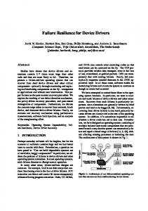
2.1. Related theories An SE induced by a particle strike can be modeled as a current source injecting into the drain of a transistor as shown in Figure 1. The value of the current or charge depends on the type of particle and its energy. The double exponential current source model from [25] as given in (1) is used for SEs induced by an alpha particle strike. /
/
(1)
This study focuses on SEs caused by neutron strikes. We employ the single exponential current source model from [26], [27] as given in (2) to represent the transient current induced by a neutron strike. /
Sootkaneung, Optimizing Device Size for Soft Error …
(2)
In (1) and (2) above, Q is the amount of particle charge deposition, and , , are the charge-collection time constants which are technology dependent. The direction of the current corresponds to whether the strike happens on a PMOS or an NMOS device [28]. We assume that the faulty state of a gate occurs when the change in gate output voltage is larger than VDD/2. The deposited charge Q which can bring the gate to this state is defined as a critical charge (Qcrit). This implies that a gate fails if corresponding transistor receives a strike of particle that induces higher energy than Qcrit. The value of Qcrit is transistor position/input dependent [23]. By carrying out extensive SPICE simulations, the Qcrit of all transistors in each gate in the library for all possible gate input patterns is identified and then mapped to the neutron flux using the JEDEC89 Standard [29] and the energy transfer model [30]. This flux provides the rate of neutron strike at a transistor which subsequently causes the gate to fail.
Figure 1: Current source model of a particle strike at sensitive transistor drain in a two-input NAND gate. To estimate the POF due to a strike on a transistor, the logical masking probability of corresponding gate must be precomputed. For a gate i and a gate input vector j, the error count, Ei(j) is defined to capture the logical masking characteristic of the gate i in the target circuit. We can obtain the error count by performing logic simulations for a given set of input vectors. For each circuit input, the output of each gate, one at a time, is flipped to its complementary value and Ei(j) is updated only when the effect of the flip can propagate to the circuit primary output. Using (3), we can calculate, Tr POFi(t, j), the POF of transistor t of a gate i for the gate input vector j. ,
,
,
(3)
In the equation above, k is the total number of simulated input vectors, , , is the probability that the energy level of neutron strike at transistor t of gate i and input j can flip its output (neutron energy greater than corresponding Qcrit), is the active area of transistor t of gate i (drain area of is the weighting the transistor which was hit), and factor, the ratio of the active area to the circuit area. The POF of a gate and of a circuit can be calculated by summing the POF of transistors in the gate and of all gates in the circuit, respectively.
The JEDEC89A standard [29] is used to obtain the neutron flux information. We estimate the probability , , by integrating corresponding neutron flux to the upper limit of 6 MeV, which can induce 120 fC of charge deposition in silicon, because beyond this point, the chance that a device receives a strike by neutron particles of energy higher than this is negligibly small [18]. Since we take gate input dependent characteristic of , , into account, our simulation results are expected to have relatively high accuracy compared to the previous works that do not account for this behavior [13], [14], [18], [20], [21], [22].
In this section, we introduce an optimization based approach for SER reduction in sub-micron circuits. The work in [23] established that in a CMOS gate, the transistors in the serial network are most sensitive to particle strikes but the SER of the gate can be reduced sharply by upsizing the parallel transistor network. Therefore, in this study, we distribute the additional area to the transistors in parallel network of each gate. Finally, we report reliability improvement and CPU runtime results for various benchmark circuits.
2.2. Related studies
We formulate circuit POF minimization as a nonlinear optimization problem. In this formulation, sizing factor of each transistor is defined as a variable and the area overhead is considered as a constraint. To begin with, the definitions of all notations are given and the notation is explained using the example circuit and device notations shown in Figure 2.
Recently, many approaches to increase SE resilience have been developed. A Gate sizing technique with simultaneous optimization of multiple objectives was introduced in [21]. In that study, a first order model of SEs in combinational circuits, which also incorporates delay and power metrics, was developed. In that study, nodes with high masking probability are selected to be optimized and the objective function is defined as a linear function. This technique is highly efficient in CPU time. However, the linear formulation requires many approximations and therefore may produce less accurate optimization results. An SE optimization of 0.18 µm standard cell circuits based on gate sizing and multi-objective genetic algorithm (MOGA) was proposed in [22]. Although the expression for SER includes the effect of all three masking factors: logical, electrical, and latching-window masking, the constant neutron flux assumed in that study may lead to erroneous conclusions. Many heuristic techniques to combat SE through sizing have also been proposed. A fault sensitivity based technique was applied to analog-to-digital converters (ADCs) to increase the circuit reliability against alpha particle strikes [17]. In this study, only mix-signal subcircuits in an ADC which have high POF are upsized. Although its use of SPICE level simulation is not practical for large scale circuits, the local redesign approach proposed in that study can be adapted for use in gate level simulation of large circuits. A sizing technique in [20] selected sensitive gates to be upsized based on logical masking probability of each gate. They chose a large value of Qcrit and adjusted gate size such that the induced current from a particle strike is suppressed. Therefore, it results into a large area overhead. The input dependent characteristic of SER has been indentified in several SER reduction studies [19], [23], [24], [31]. Only the work in [24] takes advantage of this behavior by reconfiguring the gate inputs into configurations that minimize the circuit POF without any area overhead. For this reason, our study initializes all gate inputs of the experimental/benchmark circuits using the gate input reconfiguration technique proposed in [24] before performing further reliability improvement. In [24], it was also discovered that, upsizing all devices in sub-90 nm technology node circuits may increase the circuit SER.
3. Optimization solution for device size management Sootkaneung, Optimizing Device Size for Soft Error …
3.1. Methodology
Figure 2: Circuit and device notations. • – number of input pins of a gate i. • i(t, j) denotes a transistor t in a gate i and j is the input pattern for this gate. The transistor index t varies from 1 to 2ni and the input index j varies from 1 to 2 • tpp and tsq are parallel transistor p and serial transistor q. Both p and q index of transistors in a gate i vary from 1 to ni. • xpi – upsizing factor of the parallel network of a gate i. • , – initial Qcrit value of a transistor t in a gate i for a gate input j. • – number of generated input vectors. – original area of parallel transistors of a gate • and – original drain area of parallel i: transistors and serial transistors of a gate i, respectively. – original circuit area: – circuit • area after upsizing. In Figure 2, Gate1 (NAND) and Gate2 (NOR) receive current input index j = 3 (logic “10”) and j = 2 (logic “01”), respectively. The notation of initial Qcrit values of all transistors in these gates corresponding to the current gate input vectors are illustrated in the figure.
When the parallel network receives an additional area by a factor of xpi, this does not change the value of Qcrit of a parallel transistor tpp but increases the original Qcrit of the corresponding serial transistor tsq in the complementary circuit to , . The Qcrit of the transistor tsq after upsizing the parallel network by a factor xpi is given by the following equation:
The POF of the circuit can be obtained by summing the POF of each gate i. A set of equality and inequality can be stated as a nonlinear optimization problem over a set of xpi variables as expressed in (8), (9), and (10).
Subject to: ∑ ,
#
min ∑ #
(8) ·
1
and is a nondecreasing function of . We also where precalculate , , by fitting it into an exponential function shown in (5) ,
, /
,
· ∑
∑
·
(5)
,
,
·
#
·
1
Table 1: Benchmark circuits Circuit
Number of Primary Inputs
Number of Primary Outputs
Number of Gates
C432
36
7
159
C499
41
32
578
C1196
32
31
472
C1908
33
25
459
C6288
32
32
2672
i1
25
13
40
i2
201
1
148
i3
132
6
138
i4
192
6
184
i5
133
66
288
i6
138
67
340
i7
199
67
512
i8
133
81
1685
S13207
700
790
9577
S15850
611
684
12101
Sootkaneung, Optimizing Device Size for Soft Error …
(7)
(10)
1
3.2. Experimental Results Our framework was implemented in an Intel Pentium
·
Acircuit is the total circuit area after optimization which can be written as in the equation below: ∑
(9)
The objective of the problem is defined as a minimization of the circuit POF as shown in (8), subject to two constraints in (9) and (10). Since only the transistors in the parallel networks are upsized, the additional circuit area in (9) is equal to the increase in the size of parallel transistors. We define an inequality constraint in (10) to ensure that no network or transistor is downsized
where a, b, and c are curve fitting constants. Equation (6) gives the POF of each gate i after the parallel network is upsized by a factor of xpi. This equation is obtained by using (3) and summing all terms together.
·
·
(4)
,
∑
∑
·
,
,
·
(6)
Core 2 Duo machine with a 3-GHz processor and 2-GB RAM running Microsoft Windows Vista. The cell library containing 2-, 3-, and 4-input NAND and NOR gates and Inverters is mapped with 45 and 65 nm technology nodes using predictive model from [32]. A subset of ISCAS (we focus on combination parts of selected ISCAS’89 circuits) and ITC benchmark suits is selected as the research prototype. The circuit statistics of all experimental benchmark circuits used to assess both optimization and heuristic based methods are given in Table 1. To capture the logical masking property of each circuit, the error count, Ei(j) was precomputed using 100,000 random input vectors. Initially, we reassigned each gate input pins to achieve the minimum circuit POF based on the gate input reconfiguration technique [24]. Next, we employ MATLAB nonlinear optimization toolbox running the active-set algorithm [33] in order to obtain the best area distribution under tight area overhead constraint of 2%. All SER results are reported in normalized form with respect to the original SER of experimental circuits after their input pins have been reconfigured. Table 2 shows the solutions from our nonlinear optimization formulas for SER minimization given in (8), (9), and (10). On average, we achieve the reliability improvement of 23% for 45 nm-circuits and 25 % for 65 nm-circuits. Although, our nonlinear optimization formulation is constructed with high accuracy model based on the transistor position/input dependent characteristic of SER and its results guarantee the optimality of the area distribution; the CPU runtimes can be very large as seen in Table 2. For larger circuits the runtimes can be prohibitive,
e.g. the circuit i8 could not complete even after two days of uninterrupted run. Therefore, this approach may not be suitable for large circuits which consist of thousands of gates. In the next section, we will introduce a heuristic based upsizing methodology to reduce the circuit POF that requires smaller computation time. Table 2: Optimization results for 45 nm and 65 nm benchmark circuits with area overhead of 2% Circuit
Minimized POF
Runtime (s)
45 nm
65 nm
45nm
65 nm
C432
0.8698
0.8854
78
86
C499
0.8776
0.8686
860
1221
C1196
0.7558
0.7323
795
975
C1908
0.8336
0.8258
878
722
i1
0.8270
0.7850
2
2
i2
0.4037
0.3456
105
121
i3
0.6283
0.5860
21
19
i4
0.7693
0.7339
65
82
i5
0.9601
0.9457
357
288
AVG
0.7695
0.7452
-
-
the smallest original POF value among the candidate gates, we then set the following equation: ∆
(12)
where is a constant. Next, we sum all additional area terms in (12) together over s sensitive gates. This summation is equal to the desired circuit area overhead as given in (13). ∑
∆
(13)
Using equations (12) and (13), the constant, obtained by (14) below:
can be
∑
(14)
4. Heuristic driven device size management This section describes a heuristic or fault-sensitivity based upsizing method for SER reduction. We introduce two algorithms for use in this technique. First algorithm is developed to distribute the extra area “fairly” to sensitive gates based on their POF values. The second algorithm considers the saturation of POF of each gate type that may happen when complementary network (in our case the parallel network) of a gate is over upsized. This will prevent an increase in POF due to the fact that a much exaggerated area also causes an increase in probability of particle strike on that part. The results of this heuristic based technique are given in the last subsection of this section.
4.1. Methodology To distribute additional area to sensitive gates, we first determine the original POF of each gate in a target circuit and sort them in descending order. Then the most sensitive s gates are selected to be upsized. In the experiment, the effect of the variation of s value on the SER result is observed for each benchmark circuit. Next, we apply our proposed algorithm that weights the area of sensitive gates based on their POF values. In this step, let POFi0 be the original POF of gate i, 1 ≤ i ≤ s, POFs0 be the original POF of gate s, be the change (decrease) in POF of gate i, 1 ≤ i ≤ and Δ s, after being upsized. Note that the additional gate area ∆ is given to the gate i to decrease its POF. The desired Δ value is set as follow: Δ
(11)
Now, since we would like to increase the area of each sensitive gate based on its relative sensitivity with respect to Sootkaneung, Optimizing Device Size for Soft Error …
Figure 3: Flowchart of heuristic based upsizing method. After each additional area from (12) has been computed, we distribute this extra area to parallel transistors in each sensitive gate. Following this, we invoke the second algorithm that takes into account the saturation effect as follows. We compare the extra area of each gate with the maximum area which is precomputed for each gate type. If the extra area from (12) is larger than the maximum value, the excess area beyond the allowed limit is stored in an area pool for redistribution to the other sensitive gates. As long as the area in the pool is still available, any gate that is more sensitive than any others gate, it has higher priority to receive the additional area until it reaches the maximum value. Figure 3 shows the flowchart that summarizes our heuristic based upsizing method.
4.2. Experimental Results In order to compare the relative performance of our proposed methods, the same conditions as in previous experiment are set. Our JAVA based simulator is applied on benchmark circuits which are mapped with 45 nm and 65 nm technology nodes. However, in this experiment, we
extend the investigation domain to include larger circuits than those investigated in the last section. We select additional experimental circuits from ISCAS’85 and ISCAS’89 (combinational parts) which contain more than ten thousand gates. We also initialize the original circuits using the gate input reconfiguration technique [24]. The area overhead is maintained at 2% but we vary the number of selected gates, s from 2% to 20% of total number of gates in each circuit.
very large circuits are only in 10s of milliseconds whereas the nonlinear optimization solution may have taken several hours or days. Table 4: Normalized POF and CPU runtimes results of heuristic based sizing technique for 65 nm benchmark circuits. s = 2% Circuit POF
Table 3: Normalized POF and CPU runtimes results of heuristic based sizing technique for 45 nm benchmark circuits. s = 2%
s = 5%
POF
Run time (ms)
C432
0.9362
C499
s = 10%
POF
Run time (ms)
7.22
0.9521
0.8896
19.04
C1196
0.7786
C1908
s = 20%
POF
Run time (ms)
POF
Run time (ms)
7.15
0.9345
7.60
0.9350
6.82
0.9132
19.11
0.9354
19.46
0.9359
19.20
13.39
0.7711
14.51
0.7990
13.16
0.8186
14.43
0.8550
14.31
0.8421
13.57
0.8449
14.41
0.8588
14.94
C6288
0.9541
42.62
0.9424
41.78
0.9367
41.95
0.9362
42.06
i1
0.8907
2.42
0.8553
2.62
0.8273
2.36
0.8417
2.20
i2
0.5375
8.78
0.5332
9.63
0.5356
7.76
0.5372
7.23
i3
0.6768
7.03
0.6553
7.02
0.6778
6.70
0.6982
8.09
i4
0.8502
11.57
0.7874
11.47
0.8133
11.01
0.8363
11.28
i5
0.9777
10.47
0.9634
10.60
0.9681
10.74
0.9728
10.77
i6
0.9873
23.88
0.9858
23.52
0.9840
23.44
0.9711
23.73
i7
0.9048
28.63
0.8379
27.74
0.8305
29.13
0.8674
28.18
i8
0.8892
70.81
0.8750
71.13
0.8944
69.84
0.8791
71.33
S13207
0.8992
186.70
0.8986
186.27
0.9153
185.48
0.9300
195.72
S15850
0.9299
254.92
0.9223
272.23
0.9360
258.84
0.9504
277.10
Ave.
0.8638
-
0.8490
-
0.8555
-
0.8646
-
Circuit
Tables 3 and 4 show the comparison of CPU runtime and normalized POF of selected benchmark circuits for 45 nm and 65 nm technology nodes when we perform faultsensitivity based upsizing with different s values. It is seen in these tables that on average, s values that give the largest reliability improvement for 45 nm and 65 nm circuits are 5% and 10%, respectively. However, appropriate s values depend on either circuit type or technology node; for instance, the circuit C499 has the smallest normalized POF at s = 2% for both 45 nm and 65 nm technologies, whereas the circuit i8 gains the largest improvement at s = 5% for 45 nm technology but at s = 20% for 65 nm technology. It is evident from these experimental results that our proposed heuristic driven based upsizing method provides comparable reliability improvement to the optimal solution obtained in the previous section for nearly all of the small circuits. The gains for the larger circuits are also equally impressive though the optimization based technique could not be used for these circuits. Efficiency of our heuristic based sizing technique is evident from the fact that the run times for the Sootkaneung, Optimizing Device Size for Soft Error …
s = 5%
Run time (ms)
POF
s = 10%
Run time (ms)
POF
s = 20%
Run time (ms)
POF
Run time (ms)
C432
0.9235
7.26
0.9345
7.49
0.9136
6.96
0.9152
6.95
C499
0.8936
19.70
0.9132
19.80
0.9310
20.34
0.9261
20.16
C1196
0.7758
14.80
0.7510
14.14
0.7728
13.15
0.7912
14.14
C1908
0.8683
14.21
0.8428
14.97
0.8352
13.70
0.8433
15.49
C6288
0.9434
42.63
0.9301
42.15
0.9198
45.94
0.9182
48.66
i1
0.8831
2.46
0.8277
2.51
0.7890
2.25
0.7984
2.23
i2
0.4596
7.73
0.4490
8.21
0.4496
7.34
0.4502
7.54
i3
0.6499
6.59
0.6071
6.94
0.6234
7.29
0.6453
6.37
i4
0.8438
12.06
0.7612
12.46
0.7755
11.42
0.8000
11.49
i5
0.9676
10.68
0.9496
11.33
0.9536
10.94
0.9588
10.55
i6
0.9921
24.91
0.9823
23.92
0.9777
26.00
0.9628
27.38
i7
0.9052
28.32
0.8260
29.26
0.8136
28.78
0.8505
29.10
i8
0.8966
70.96
0.9022
71.47
0.8788
73.49
0.8573
74.83
S13207
0.8883
188.83
0.8797
193.90
0.8991
189.21
0.9149
190.68
S15850
0.9186
251.87
0.9024
257.02
0.9172
263.33
0.9348
257.92
Ave.
0.8540
-
0.8306
-
0.8296
-
0.8378
-
5. Discussions The basis of our heuristic based approach is to provide more areas to the gates that have higher SE vulnerability. The validity of this argument can be established by looking at the results of the optimization based sizing method. Figure 4 compares the results from our optimization based technique with our heuristic based technique for a benchmark circuit C1908 with 65 nm technology node. The optimization results reveal that additional area is selectively distributed to only the topmost 20% sensitive gates (90 out of 549 gates) as seen in Figure 4 (solid line plot in the figure). We also notice that for the optimization based approach, the most sensitive gates tend to receive large sizing factor. The optimal results for the circuit C1908 show that only 20% of all gates are selected to be upsized. In our heuristic based method, we set the number of selected gates, s = 20% for the fault-sensitivity based sizing technique, same as provided by the optimization based approach. The transistor upsizing factor for heuristic based method for the circuit C1908 is also shown in Figure 4. Although the heuristic based method does not assign same as the optimization based approach, we notice from the two traces shown in Figure 4 that the two approaches have very good correlation in assigning the extra area. As a result, we can expect our proposed fault-sensitivity based technique to give near
optimal reliability improvement. We noticed similar trends for the other circuits, though the value of s differs from circuit to circuit. 3
Parallel Transisotr Sizing Factor
2.5 Heuristic based 2
as much as 3-55%, with appropriate number of selected gates and the same area overhead as in the first method. More importantly, the fault-sensitivity based technique requires relatively small computation time, 10s of milliseconds for large circuits consisting of thousands of gates, compared to the nonlinear optimization problem which may require several hours to generate the optimal solution.
7. Acknowledgment
Optimization based
This work is in part supported by the National Science Foundation under Grant CPA-0811467.
1.5 1
8. References
0.5 0 1
11
21
31
41
51
61
71
81
91
101
Most Sensitive Gate Index
Figure 4: Area distribution performed by the optimization and heuristic based (with s = 20%) sizing techniques in the circuit C1908 with 65 nm technology nodes. Instead of using heuristic based approach to reduce CPU time while obtaining near optimal distribution of area overhead to different gates, two possible alternatives are 1) reduce the number of variables in the optimization formulation, or 2) use an approximate linear optimization formulation. The results of approximate linear optimization, as in [21], are expected to be less than accurate. The number of variables in the nonlinear formulation can be reduced as follows. We can choose to assign the extra area only to a selected set of s most sensitive gates, thus setting the variable xpi = 1 for all those gates which are not in the select set. Such a method will reduce the solution time substantially if s is relatively small. However, the problem is to determine a good value of s. Our initial experimentation suggests that the value of s varies from circuit to circuit and it is difficult to determine a priori.
6. Conclusions This paper proposed two techniques for optimizing device size to reduce SER in sub-micron logic circuits. The methodology employs transistor position/input dependent model of SER [23], [24], which makes our sizing techniques highly accurate. Further, the two sizing methods proposed in this paper upsize only transistors in complementary network in a gate to improve SER of nanometer technologies. Our optimization based technique formulates SER minimization as a nonlinear optimization problem. The optimal results from this approach guarantee the best area distribution within a given budget. For a very tight area budget of 2% overhead, this technique results in substantial reliability gains ranging from 4-65% for various experimental circuits. The second sizing technique is developed based on faultsensitivity of each sensitive gate. The algorithms for weighting the gate area and limiting gate POF are adapted to enhance its operational capability. Our heuristic based approach also provides impressive reliability improvement, Sootkaneung, Optimizing Device Size for Soft Error …
[1] Y. Tosaka et al., "Cosmic ray neutron-induced soft errors in sub-half micron CMOS circuits," IEEE Electron Device Letters, pp. 99-101, March 1997. [2] S. Mitra, N. Seifert, M. Zhang, Q. Shi, and K. S. Kim, "Robust System Design with Built-In Soft-Error Resilience," Computer, vol. 38, no. 2, pp. 43-52, Feburary 2005. [3] S. Mitra, M. Zhang, N. Seifert, T.M. Mak, and K. S. Kim, "Built-In Soft Error Resilience for Robust System Design," in IEEE International Conference on Integrated Circuit Design and Technology, Austin, TX, 2007, pp. 1-6. [4] F. Wang and V. D. Agrawal, "Single Event Upset: An Embedded Tutorial," in the 21st International Conference on VLSI Design, Hyderabad, India, 2008, pp. 429-434. [5] H. R. Zarandi and S. G. Miremadi, "Soft Error Mitigation in Cache Memories of Embedded Systems by Means of a Protected Scheme," Lecture Notes in Computer Science, Springer Berlin / Heidelberg, vol. 3747, pp. 121-130, 2005. [6] V. Gherman, S. Evain, M. Cartron, N. Seymour, and Y. Bonhomme, "System-Level Hardware-Based Protection of Memories against Soft-Errors," in the DATE 2009, Nice, France, 2009, pp. 1222-1225. [7] A. Biswas et al., "Explaining Cache SER Anomaly Using DUE AVF Measurement," in the 16th IEEE International Symposium on High-Performance Computer Architecture (HPCA), Bangalore, India, 2010, pp. 1-12. [8] N. Oh, P. P. Shirvani, and E. J. McCluskey, "Error Detection by Duplicated Instructions in Super-Scalar Processors," IEEE Transaction on Reliability, vol. 51, no. 1, pp. 63-75, March 2002. [9] G. A. Reis, J. Chang, N. Vachharajani, R. Rangan, and D. August, "SWIFT: Software Implemented Fault Tolerance," in the International Symposium on Code Generation and Optimization, Washington, DC, 2005, pp. 243-254. [10] J. Lee and A. Shrivastava, "A Compiler Optimization to Reduce Soft Errors in Register Files," in the 2009 Conference on Languages, Compilers, and Tools for
Embedded Systems, Dublin, Ireland, 2009, pp. 41-49. [11] M. Fazeli, A. Namazi, and S. G. Miremadi, "Robust Register Caching: An Energy Efficient Circuit-level Technique to Combat Soft Errors in Embedded Processors," IEEE Transactions on Device and Materials Reliability, vol. 10, no. 2, pp. 208-221, June 2010. [12] A. U. Diril, Y. S. Dhillon, A. Chatterjee, and Singh A. D, "Design of Adaptive Nanometer Digital Systems for Effective Control of Soft Error Tolerance," in the 23rd IEEE VLSI Test Symposium (VTS 2005), Palm Springs, CA, 2005, pp. 298-303. [13] R. R. Rao, D. Blaauw, and D. Sylvester, "Soft Error Reduction in Combinational Logic Using Gate Resizing and Flipflop Selection," in the 2006 IEEE/ACM international Conference on ComputerAided Design, San Jose, CA, 2006, pp. 502-509. [14] E. L. Hill, M. H. Lipasti, and K. K. Saluja, "An Accurate Flip-Flop Selection Technique for Reducing Logic SER," in the International Conference on Dependable Systems and Networks (DSN 2008), Anchorage, AK, 2008, pp. 128-136. [15] S. Mitra, "Robust System Design," in the 23rd International Conference on VLSI Design, Bangalore, India, 2010, pp. 434-439. [16] J. W. Choi, B. Shim, A. C. Singer, and N. I. Cho, "Low-Power Filtering via Minimum Power Soft Error Cancellation," IEEE Transactions on Signal Processing, vol. 55, no. 10, pp. 5084-5096, October 2007. [17] M. Singh and I. Koren, "Fault-Sensitivity Analysis and Reliability Enhancement of Analog-to-Digital Converters," IEEE Transactions on Very Large Scale Integration (VLSI) Systems, vol. 11, no. 5, pp. 839-852, October 2003. [18] H. S. Deogun, D. Sylvester, and D. Blaauw, "GateLevel Mitigation Techniques for Neutron-Induced Soft Error Rate," in the 6th International Symposium on Quality of Electronic Design (ISQED2005), San Jose, CA, 2005, pp. 175-180. [19] N. Miskov-Zivanov and D. Marculescu, "MARS-C: Modeling and Reduction of Soft Errors in Combinational Circuits," in the 43rd Annual Design Automation Conference (DAC’06), San Francisco, CA, 2006, pp. 767-772. [20] Q. Zhou and K. Mohanram, "Gate Sizing to Radiation Harden Combinational Logic," IEEE Transactions on Computer-Aided Design of Integrated Circuits and System, vol. 25, no. 1, pp. 155-166, January 2006. [21] K. Bhattacharya and N. Ranganathan, "Reliabilitycentric Gate Sizing with Simultaneous Optimization of Soft Error Rate, Delay and Power," in the International Symposium on Low Power Electronics and Design (ISLPED 08), Bangalore, India, 2008, pp. 99-104. [22] W. Sheng, L. Xiao, and Z. Mao, "Soft Error Sootkaneung, Optimizing Device Size for Soft Error …
Optimization of Standard Cell Circuits Based on Gate Sizing and Multi-Objective Genetic Algorithm," in the 46th Annual Design Automation Conference (DAC'09), San Francisco, CA, 2009, pp. 502-507. [23] W. Sootkaneung and K. K. Saluja, "Sizing Techniques for Improving Soft Error Immunity in Digital Circuits," in the International Conference on VLSI Design and Communication Systems (ICVLSICOM-10), Chennai, India, 2010, pp. 87-92. [24] W. Sootkaneung and K. K. Saluja, "Gate Input Reconfiguration for Combating Soft Errors in Combinational Circuits," in the 4th Workshop on Dependable and Secure Nanocomputing, Chicago, IL, 2010, in press. [25] G. C. Messenger, "Collection of Charge on Junction Nodes from Ion Tracks," IEEE Transactions on Nuclear Science, vol. 29, no. 6, pp. 2024–2031, 1982. [26] P. Hazucha and C. Svensson, "Impact of CMOS Technology Scaling on the Atmospheric Neutron Soft Error Rate," IEEE Transactions on Nuclear Science, vol. 47, no. 6, pp. 2586-2594, December 2000. [27] P. Shivakumar, M. Kistler, S. W. Keckler, D. Burger, and L. Alvisi, "Modeling the Effect of Technology Trends on the Soft Error Rate of Combinational Logic," in the International Conference on Dependable Systems and Networks (DSN 2002), Bethesda, MD, 2002, pp. 389-398. [28] C. Hungse, E. M. Rudnick, J. H. Patel, R. K. Iyer, and G. S. Choi, "A Gate-Level Simulation Environment for Alpha-Particle-Induced Transient Faults," IEEE Transactions on Computers, vol. 45, no. 11, pp. 12481256, November 1996. [29] JEDEC89A Standard, "Measurement and Reporting of Alpha Particles and Terrestrial Cosmic Ray-Induced Soft Errors in Semiconductor Devices," Joint Electron Device Engineering Council, Solid State Technology Association, 2006. [30] D. G. Mavis and P. H. Eaton, "Soft Error Rate Mitigation Techniques for Modern Microcircuits," in the 40th International Reliability Physics Symposium , Dallas, Texas, 2002, pp. 216-225. [31] B. Zhang, W. Wang, and M. Orshansky, "FASER: Fast Analysis of Soft Error Susceptibility for Cell-Based Designs," in the 7th International Symposium on Quality Electronic Design (ISQED 2006), Washington, DC, 2006, pp. 755-760. [32] HSPICE PTM website. [Online]. Available: http://www.eas.asu.edu/~ptm. [33] Mathworks website. [Online]. Available: http://www.mathworks.com.