Available online www.ejaet.com European Journal of Advances in Engineering and Technology, 2015, 2(3): 46-50
Research Article
ISSN: 2394 - 658X
Orthogonal Frequency Division Multiplexing Modulation Scheme for 4G/5G Cellular Network Santosh M Nejakar1, Prabhu G Benakop2 and Sharanabasappa R R1 1
Department of E&TC, Sanjay Ghodawat Institutions, Atigre, Kolhapur, India Department E&C, Indore Institute of Engineering and Technology, Hyderabad, India
[email protected] _____________________________________________________________________________________________ 2
ABSTRACT The next generation wireless communications systems need to be of a higher standard in order to provide the customers with the multitude of high quality services they demand. Orthogonal frequency division multiplexing (OFDM) is a key technique for achieving high data rates and spectral efficiency requirements for wireless communication systems OFDM is becoming the chosen modulation technique for wireless communications. OFDM can provide large data rates with sufficient robustness to radio channel impairments. The purpose of this paper is to implement the basic processing involved in the transmission and reception of an OFDM technique. The implementation of OFDM is done in MATLAB. Key words: Orthogonal frequency division multiplexing (OFDM), fast Fourier transformer (FFT), frequency division multiplexing (FDM)
__________________________________________________________________________________ INTRODUCTION With the rapid growth of digital wireless communication in recent years, the need for high-speed mobile data transmission has increased. In the wireless environment signals are usually impaired by fading and multipath delay phenomenon, traditional single carrier mobile communication systems do not perform well. In such channels, extreme fading of the signal amplitude and Inter Symbol Interference (ISI) occurs at the receiver side. This leads to a high probability of errors and the system’s overall performance becomes very poor. Techniques like channel coding and adaptive equalization have been widely used as a solution to these problems. However, due to the inherent delay in the coding and equalization process and high cost of the hardware, it is quite difficult to use these techniques in systems operating at high bit rates [5] New modulation techniques are being implemented to keep up with the desire more communication capacity Orthogonal Frequency Division Multiplexing (OFDM) is a key technique for achieving high data rates and spectral efficiency requirements for wireless communication systems. Orthogonal Frequency Division Multiplexing (OFDM) transmissions are emerging as important modulation technique because of its capacity of ensuring high level of robustness against any interference [4] In an OFDM scheme a large number of sub channels or sub-carriers are used to transmit digital data. Each sub-channel or sub-carriers divide the available bandwidth and each sub-carrier is orthogonal to every other. They are closely spaced and narrow band. The separation of the sub-channels is as minimal as possible to obtain high spectral efficiency. The purpose of this project is to implement the basic processing involved OFDM technique. The implementation of OFDM is done in MATLAB. The aim of this paper is to implement a baseband OFDM processing. Including FFT (Fast Fourier Transform) and IFFT (Inverse Fast Fourier Transform), which satisfy to overcome from ISI (Inter Symbol Interference) and avoiding overlapping of signals. THEORY OF OFDM In classical parallel data system, the total signal frequency band is divided into N non-overlapping frequency sub-channels. Each sub-channel is modulated with a separate symbol, and then the N sub-channels are frequency multiplexed. It seems good to avoid spectral over-lap of channels to eliminate inter-channel
46
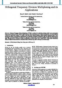
Nejakar et al Euro. J. Adv. Engg. Tech., 2015, 2(3):46-50 ___________________________________________________________________________ interference. However it leads to inefficient use of available spectrum. As like in Frequency Division Multiplexing (FDM), shown in Fig. 1, requires separation of the channels. In radio-based FDM, there must be a space, or guard band between channels to avoid interference from adjacent channels. These empty spaces are not efficient use of the spectrum [1]. So to cope up with this inefficiency, the idea is to use parallel data and FDM with overlapping sub-channels. One modulation scheme of recent interest is Orthogonal Frequency Division Multiplexing (OFDM). OFDM is a multicarrier modulation technique, which divides the bandwidth into many carriers; each one is modulated by a low rate data stream and each sub-carrier is orthogonal to every other so can achieve overlapping of sub-channels. As shown in Fig. 2. This modulation is one of several that can support high data rates [2].
Fig. 1 Frequency division multiplexing
Fig. 2 Orthogonal frequency division multiplexing
Orthogonality The key to OFDM is maintaining orthogonality of the carriers. If the integral of the product of two signals is zero over a time period, then these two signals are said to be orthogonal to each other. Two sinusoids with frequencies that are integer multiples of a common frequency can satisfy this criterion. Therefore, orthogonality is defined by [3]
∫ cos(2πnf t ) cos(2πmf t )dt = 0 0
0
(n ≠ m)
(1)
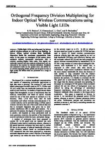
Multiple Path Effect This affects the transmission in case of the wireless transmission system. The received radio signals from the transmitter consist of a direct signal and reflections from the objects such as mountings; building, and other structures. The reflected signal arrives at a later time than the direct signal because of the extra path length. This gives rise to slightly different arrival times which spreads the received energy in time. Delay spread is thus the time spread between the arrival of the first and last significant multipath signal seen by the receiver. In digital systems, the delay spread leads to the inter-symbol interference. This causes significant errors in bit rate [2]. Inter Symbol Interference (ISI) Inter-Symbol Interference takes place when a given transmitted symbol is distorted by other transmitted symbols. BLOCK DIAGRAM OF OFDM The implementation of OFDM is carried out as follows the Fig. 3.
Fig. 3Orthogonal Frequency Division Multiplexing system (a) Transmitter, (b) Receiver
Data In Stream of binary sequence are generated. Here 64 bits of binary sequence (0’s and 1’s) are generated and feed to serial to parallel converter. Serial to Parallel Here we convert the input serial bit stream into several parallel bit streams to divided whole bandwidth among the individual carriers. The data allocated to each symbol on individual carriers depends on the modulation scheme used and the number of subcarriers.
47
Nejakar et al Euro. J. Adv. Engg. Tech., 2015, 2(3):46-50 ___________________________________________________________________________ Modulation Modulation is the process of modifying some properties of the high frequency carrier signal in accordance with the baseband signal [2]. Here QPSK modulation is used. This modulation scheme is characterized by the fact that the information carried by the transmitted wave is contained in the phase. The phase of the carrier takes one of the equally spaced values, such as /4, 3 /4, 5 /4 and 7 /4 as shown by
2E s π cos(2πf c t + (2n − 1) ) Ts 4
S n (t ) =
(n =1, 2, 3, 4...)
(2)
Fig. 4 QPSK Signal-Constellation
Inverse Fast Fourier Transform (IFFT) The IFFT takes an N symbols at a time where N is the number of subcarriers in the system. The IFFT output is the summation of all N sinusoids. Thus, the IFFT block provides a simple way to modulate data onto N orthogonal subcarriers. The block of N output samples from the IFFT make up a single OFDM symbol. IFFT is given by [3]
X
n
1 = N
N −1
∑
X
p=0
p
e
j
2π np N
, n ∈ { 0 , 1 , 2 . . . . . . . . . . N − 1}
(3)
After the IFFT guard bits are added and feed to parallel to serial. Here the guard bits added by using period time of zero amplitude transmission. This was to allow for symbol timing to be easily recovered by receiver. Parallel to Serial Once the guard bit has been added to the sub-carrier channels, they must be transmitted as one signal. Thus, the parallel to serial conversion stage is the process of summing all sub-carriers and combining them into one signal. This is the base band signal for the OFDM transmission. Fast Fourier Transform (FFT) At the receiver, an FFT block is used to process the received signal and bring it into the frequency domain. Ideally, the FFT output will be the original symbols that were sent to the IFFT at the transmitter. FFT is given by
X
p
=
N −1
∑
n=0
X ne
− j
2π np N
, p ∈ { 0 , 1, 2 . . . . . . . . . . N − 1}
(4)
Demodulation This process is the juts reverse of the modulation process. It is carried out on the receiver side of the system and is done in the frequency domain. IMPLEMENTATION AND RESULT The below flow chart shows the steps performed to implement. According to the binary sequence, the QPSK modulated output is shown in Fig.5.After the performing the IFFT the output received is shown in Fig.6. After the removing of guard bits at the receiver side the output is shown in Fig.7 and Fig. 8 depicts the output after the performing FFT at receiver ends. CONCLUSION In this paper OFDM with QPSK modulation is demonstrated .The key building blocks of an OFDM transmitter and OFDM receiver has been implemented in MATLAB and the functionality of the each blocks are studied. The modulation of data can be modelled with the help of a modulation matrix that is computed based on a given pulse shaping filter and data block size. Based on the transmitter model, known ways of receiving the signal can be applied. However, all three standard methods may, depending on the system parameters, yield strong performance degradation when compared to FFT, IFFT. Output of the QPSK modulation IFFT with adding guard bits can be calculated.
48
Nejakar et al Euro. J. Adv. Engg. Tech., 2015, 2(3):46-50 ___________________________________________________________________________
Fig. 5
Fig. 6
Fig. 7
Fig. 8
REFERENCES [1] Ender Bolat, Study of OFDM Performance over AWGN Channels, Eastern Mediterranean University, Cyprus, 2003. [2] Simon Haykin Digital communications, 4th edition, Mc Graw Hill, India, 2002. [3] John G. Proakis Digital communications, 5th edition, Pearson, India, 2001. [4] OFDM Simulation using MATLAB http://users.ece.gatech.edu/~mai/tutorial/OFDM/Tutorial_web.pdf, 2003. [5] SS.Riaz Ahamed, Performance Analysis of OFDM, Journal of Theoretical and Applied Information Technology, 1982, 4, 52-59.
49
Nejakar et al Euro. J. Adv. Engg. Tech., 2015, 2(3):1-5 ______________________________________________________________________________ [6] T Schmid and D Cox, Robust Frequency and Timing Synchronization for OFDM, IEEE Trans. Comm., 1997, 45(12), 1613–1621. [7] H Minn, M Zeng and V Bhargava, On Timing Offset Estimation for OFDM Systems, IEEE Communication Letter, 2000, 4(7), 242–244. [8] A Awoseyila, C Kasparis and B Evans, Improved Preamble-Aided Timing Estimation for OFDM Systems, IEEE Communication Letters, 2008, 12(11), 825–827. [9] C Kasparis and BG Evans, A cross-correlation approach for improved timing estimation in, OFDM broadcasting systems, 24th AIAA International Communications Satellite Systems Conferences (ICSSC), San Diego, USA, 2006, 1039–1048.
50