the sending window, until full link utilization is detected, and then to ..... Y-T. Li. Evaluation of TCP congestion control algorithms on the Windows Vista platform.
Oscillations of the Sending Window in Compound TCP 1
1
2
Alberto Blanc , Denis Collange , and Konstantin Avrachenkov 1
Orange Labs, 905 rue Albert Einstein, 06921 Sophia Antipolis, France 2 I.N.R.I.A. 2004 route des lucioles, 06902 Sophia Antipolis, France
One of the key ideas of Compound TCP is to quickly increase the sending window, until full link utilization is detected, and then to keep it constant for a certain period of time. The actual Compound TCP algorithm does not hold the window constant but, instead, it makes it oscillate around the desired value. Using an analytical model and ns-2 simulations we study these oscillations on a Linux implementation of Compound TCP, in the case of a single connection with no cross tra�c. Even in this simple case we show how these oscillations can behave in di�erent ways depending on the bandwidth delay product. We also show how it is important to take into account, in the analytical model, that some implementation subtleties may introduce non-negligible di�erences in the behavior of the protocol. Abstract.
1
Introduction
Tan et al. have introduced Compound TCP [5] to improve the performance of TCP on networks with large bandwidth delay products. One of the main ideas of this new high speed TCP variant is to quickly increase the sending window as long as the network is underutilized and then stabilizing it when a certain number of packets is bu�ered in the network. To achieve this goal the sender monitors the round trip time: as long as the network is underutilized (i.e. no packets are queued) the round trip time will not change. This corresponds to the case where the window is smaller than the bandwidth delay product. As the window is increased the sending rate will eventually surpass the capacity of the bottleneck link and the round trip time will start to increase. In particular the sender estimates the number of packets currently backlogged in the network. When this estimate is greater than or equal to a threshold
γ
the sender stops
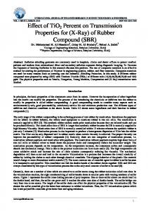
increasing its window. Figure 4 in [5], and some of the comments in that paper, give the impression that the window is then kept constant for a certain time. While this might be a useful approximation in explaining and thinking about this new TCP version, it is easy to see, from equation (5) in [5], that the window will indeed oscillate during this phase. Figure 1 shows the evolution of the sending window from an ns-2 simulation. Clearly, at least in this case, the oscillations have a non-negligible amplitude. In the remainder of this paper we are going to analyze these oscillations in the case of a single Compound TCP connection with no competing tra�c and no random losses (packets are dropped only when
window size/MSS
650 600 550 500 450 400 350 35
40
45
50
55
time/s
Fig. 1.
The evolution of the sending window between two packet drops (ns-2 simulation,
µ = 100 Mb/s, τ˜ = 69 ms)
the bu�er is full). While this is clearly the simplest possible scenario, even in this case, the oscillations have several possible patterns and, based on simulation results, their amplitude increases with the bandwidth delay product. These oscillations may have many consequences on Compound TCP �ows. Firstly, the packet loss probability in presence of other �ows, using Compound TCP or not, will be increased during this phase. This may reduce the proportion of time during which the congestion window is larger than the bandwidth delay product, and then the e�ciency of the protocol. Secondly, as these oscillations increase with the bandwidth delay product, the probability to saturate the bottleneck's bu�er and will be higher and the e�ciency will be lower in case of large round-trip times, as observed in [2]. Thirdly, these oscillations of the window, and, therefore of the bu�er occupancy, may also degrade the performance of the network, increasing the delay, the jitter and the loss rate experienced by the other �ows.
2
Evolution of the Compound TCP Window During the �Constant Window� Phase
During the �constant window� phase, every round trip time, the sender estimates
∆ (diff in ∆ positive, to use the bottleneck
the current backlog in the bu�er of the bottleneck through the variable [5]). An objective of Compound TCP is to keep at full speed, but small (close to
w(t)
γ ),
to minimize the bu�er occupancy.
t and let ti be the end of the i-th round wi to wi+1 . In order to make the w(t) a left continuous function we set w(t) = wi if ti−1 < t ≤ ti . This way w(ti ) = wi . Throughout this paper we will assume that w is expressed in terms of packets, or Maximum Segment Size (MSS). Note that ti−1 − ti is one round trip time Let
be the window size at time
trip, when the window is increased from
so that the expression �every round trip time� refers to the time between two increments of the window. In the absence of loss, Compound TCP increments the window in the following way (see [5] for a complete description):
( wi+1 =
wi + αwik , if ∆i < γ wi − ζ∆i + 1 , if ∆i ≥ γ
(1)
with
∆i = w i Where
τ˜
�
τ˜ 1− τi
�
.
(2)
is the smallest round trip time observed so far, and
τi
is the latest
estimate of the round trip time. For the remainder of the paper we assume that
ζ = 1,
and for all numerical example we use
α = 1/8, γ = 30,
and
k = 3/4,
as suggested by the authors of CTCP [5]. While selecting these values is an interesting problem in itself it is outside the scope of this work (see [5] for more details). Clearly as
w
∆i and, as the round-trip time is an increasing ∆ > γ ; and the window will be decreased, proin the meantime. Similarly, as smaller values of w
increases so does
function of window, eventually vided no packets are dropped imply smaller values of
∆,
the window will be increased again. In other words
one or more increasing phases are followed by one or more decreasing phases. We call a �cycle� the collection of increasing and decreasing phases starting with the �rst increasing phase and ending with the last decreasing phase. Figure 2 shows two possible cycles, the one on the left has 3 increasing phases and 1 decreasing phase, while the one on the right has 4 and 2, respectively. We will use two integers to classify cycles, with the �rst one representing the number of increments and the second one the number of decreasing phases. A 5:2 cycle, for example, has
5
increments and 2 reductions. In the �gure dots and circles represents the
value of the window before and after each increment, respectively.
w4 w ˆ4 w3 w ˆ3
w5 w ˆ5 w4 w ˆ4
w
w
w3 w ˆ3
∆4
µτ
w2 w ˆ2
∆5
∆6
w ˆ2 w2
w1 w ˆ1
µτ
w1 w ˆ1 u1 t1 u2 t2
u3 t3
u4 t4 Fig. 2.
t
u1 t1 u2 t2
u3 t3
The 3:1 and 4:2 cycles
u4 t4 u5 t5
u6 t6
t
The sending window of Compound TCP is the sum of two components that are incremented independently during each round trip time. The congestion component is incremented by one each round trip time, just like the window in TCP Reno. While the delay component (wd ) is incremented, once per round trip time as well, as
wd = wd + αwk − 1.
The minus one compensates for the increase
of the congestion component so that the total window grows as
w = w + αwk .
Similarly the plus one in (1) comes from the increment of the congestion window component, which happens also during the round trip time when the delay component is decreased. So that in a m:n cycle there are component and
m+n
m
increments of the delay
increments of the congestion component. In Figure 2 the
smaller increments, between
w ˆi
and
wi ,
represent the increments of the conges-
tion component and they take place at time
ui
while the bigger increments are
due to the delay component and take place at time
ti .
Note that
w1
is the value
after the initial increment of the congestion window, such increment represents
the increment of the congestion window corresponding to the last reduction of the delay component at the end of the previous cycle.
2.1
Linux Implementation
In order to study the behavior of Compound TCP we ran simulations using ns-2 version 2.33 [4] with a Compound TCP implementation for Linux [1]. This implementation uses a slightly di�erent formula to compute uses
wi−1
∆i :
instead of
wi
∆i = wi−1 (1 − τ˜/τi ). Recall that that
wi−1
wi
(3)
is the value of the window before the increment at time
is the value of the window during
(ti−2 , ti−1 ].
wi . One way of thinking about ∆i
ti
so
While [5] is somewhat
vague about the details of these computations, it is appropriate to use stead of
it
so that (2) is replaced by:
wi−1
in-
is that it tries to estimate the number
of backlogged packets by comparing the current round trip time with the smallest round trip time observed so far. Given that the sender uses acknowledgments to measure the round trip time, any such sample corresponds to the round trip time experienced by the packet last acknowledged and such a packet was sent when
w = wi−1 .
In other words all the round trip samples are �one round trip
time old.� Another aspect to take into account is that, while it is possible to �nd several equivalent expression for
∆i , the Linux
kernel does not use �oating point opera-
tions. So that all the operations have to be approximated with integer ones. This introduces an error that can be minimized but that can lead to non-negligible di�erences between the implemented protocol and a theoretical model. In order to minimize the approximation error
∆i
is computed as:
2∆i = 2wi−1 − and
γ
is multiplied by
2
�
2wi−1 τ˜ τ
�
∆i . (We use bxc to x.) Computing the window increment αwnk presents
whenever it is compared with
represent the integer part of
(4)
a similar problem. As
α = 1/8
k = 3/4 (as suggested $ %% 28 wn 1 p √ 23 216 wn
and
formula is used:
$ αwnk =
where all the multiplications (and divisions) by a power of
in [5]) the following
(5)
2 are implemented as
shift operations and the square root is implemented using the int_sqrt() function of the Linux kernel.
2.2
Modeling the Linux Implementation
For the case of a single connection with no other tra�c
τ˜
is equal to the prop-
agation delay, which we assume to be known. In this case it is also possible to express
τi
(the latest estimate of the round trip time) as a function of the
window and the bottleneck capacity
µ.
In the Linux kernel the round trip times
are measured in microseconds so that, even if integers are used, the precision is extremely high. Assuming that the backlog is non-zero, we can compute the round trip time dividing the window by the bottleneck capacity so that:
τi = min
��
� � wi−2 + 1 , τ˜ . µ
(6)
This is is because the implementation in question uses the smallest round trip time sample among all the samples collected during the last round trip time, between
ti−1
and
ti .
(One comment in the source code explains that the choice
of using the smallest round trip sample is to minimize the e�ect of delayed acknowledgments.) As the window, and therefore the round trip time, is an increasing function of time, the smallest value corresponds to the smallest time value; that is the beginning of the round trip. For example in Figure 2, at time
t4 t2 t3
the sender considers all the samples relative to the packets sent between times
to
but, while this increment is instantaneous, the round trip time grows
(excluded) and (excluded) and
w3 ,
t3 (included), whose acknowledgments were received between t4 (included). At time t2 the window was increased from w2
by smaller increments (more precisely by
1/µ)
so that the smallest round trip
sample observed between t3 and t4 corresponds to the packet that was sent when the window was
w2 + 1. Clearly τi cannot be smaller than the propagation delay, τ˜. This can indeed happen as wi can be smaller than
hence the minimum with
µ˜ τ,
either during the initial growing phase during the oscillation phase in the
case of multiple reductions. In [5] the authors say that the window should be updated �once per round trip time.� The implementation we used accomplishes this as follows: whenever the window is updated the sequence number of the next segment to be transmitted (say
ni ) is recorded. Once the corresponding acknowledgment arrives the
window is updated another time. As a consequence, whenever the window is reduced because
∆≥γ
the next segment cannot be sent immediately (the win-
dow is smaller than the number of unacknowledged packets). The sender resumes
transmission only after receiving acknowledgments for
∆
packets. Due to this
pause in the transmission the backlog experienced by packet
ni
is smaller. When
the corresponding acknowledgment arrives the round trip time (for this packet) is:
τi = min Where
ti−1
wi−1 − ∆i−1
��
� � wi−1 − ∆i−1 , τ˜ . µ
(7)
is the window size after the reduction. Therefore, if at time
the window was reduced,
ti
(i.e. the beginning of the new round trip time)
corresponds with the arrival of the acknowledgment for packet
ni .
As we have
already mentioned, the implementation we have used takes the smallest of all the round trip samples collected between the last window update, at time (excluded), and the current time window was reduced at
ti−1 ,
ti
ti−1
(included). This implies that, each time the
the smallest round trip time sample is due to the
last acknowledgment received. And the corresponding packet is the �rst one sent after the transmission pause. Note that, provided the queue at the bottleneck link does not empty during the pause, when the sender resumes sending packets the backlog size will not change until the window is updated at time ti . This implies that the value given by (7) is actually the �true� value of the round trip time between and
ti
, where
∆i−1 /µ
ti−1 + ∆i−1 /µ
is the duration of the transmission pause (it is the time
needed to receive enough acknowledgments to compensate for the reduction of the window). Given that we have de�ned a cycle as a series of increasing phases followed by one or more decreasing phase, the �rst phase of a cycle will always follow a window reduction so that, at
wm − ∆m = w1 − 1, that we have de�ned
where
w1
m
t1
(7) is used. In this case we also have that
is the last phase of the previous cycle. (Recall
as the value after the �rst increment of the congestion
τ1 = (w1 − 1)/µ. At time t2 the smallest round t1 and t2 is again τ1 because the packets whose acknowledgments arrive during (t1 , t2 ] were sent between during (tm +∆m /µ, t1 ]. component.) And we can write
trip samples received between
As previously observed, all the packets sent during this time experience the same round trip time: In general,
τi
(wm − ∆m )/µ. is given by (6) unless the window was reduced at time
in which case (7) should be used, or if the window was reduced at time
ti−1 , ∆i (3)
τi = τi−1 .
ti−1 , ti−2
and incremented at time
in which case
together with those for
and for the window increment (5) it is possible
Using these formulas,
to model the evolution of the window. At the same time it is important to use the same integer approximations used in the Linux kernel: for example if we compute
w4 (w1 )
starting value of
(that is the value of the window after three increments with a
w1 )
using the same formulas used in the Linux Kernel or using
�oating point operations the di�erence between the two quantities is between 0 and 2. Where we use the formula compute Figure 3
∆i
αwnk
to compute the window increment and
∆i = wi (1 − τ˜/τ ) when we use �oating point operations. Finally, compares ∆5 using integer and �oating point operations. as
600
∆5 (Linux Impl.) ∆5
x3:1 z3:1 x4:2 z4:2
580
window size/MSS
window size/MSS
40
35
30
25
560 540 520 500 480 460
500
550
600
650
700
460
480
w1 /MSS
Fig. 3.
520
540
560
˜ µ τ/MSS
∆5 using �oating point and integer
operations
3
500
Solutions of the �xed point equation for the 3:1 and 4:2 cycles using �oating point (z ) and integer (x) operations Fig. 4.
Fixed Points
Given that, as previously discussed, a series of increasing phases is always followed by one or more decreasing phases it is natural to ask if such oscillations follow a speci�c pattern and, above all, if they reach a steady state. It is su�cient to look at a few simulations to guess that oscillations do reach a steady state very quickly (after one or two cycles). Depending on the system parameters, we have observed 5 types of cycles: 3:1, 2:1, 5:2, 4:2 and 3:2. For each cycle type it is possible to �nd the steady state solution by numerically solving a �xed point equation. For the 3:1 cycle, for example, if
w1
is the value of
the window at the beginning of each phase the value at the end of the cycle is
f3:1 (w1 ) , w4 (w1 ) − ∆4 (w1 ) + 1
where
wn+1 = wn + αwnk and ∆4 is given by w1 so that solving the �xed point
(3). Note that the only independent variable is equation
f3:1 (w1 ) = w1
it is possible to �nd the steady state solution. The plus
one takes into account the fact that, during each cycle, there are three increments of both window components and one increment (by one) of the congestion component combined with one reduction of the delay component. To be precise, here
w1
corresponds to the initial value of the total window after an increment
by one of the congestion component (see Figure 2). For each cycle m:n it is possible to de�ne the corresponding function fm:1 (w1 ) = wm+1 (w1 ) − ∆m+1 (w1 ) + 1 if n = 1 and fm:n = wm+1 (w1 ) − ∆m+1 (w1 ) − ∆m+2 (w1 ) + 2 if n = 2. For the latter case the plus two compensates for the two increments of the congestion component corresponding to the two reductions of the delay component. Figure 4 shows the solution of
f3:1
and
f4:2
as a function
of the bandwidth-delay product (µ˜ τ ). In this case the di�erence between using �oating point and integer operations is not very signi�cant, especially for the 4:2 case where the error is negligible. While Figure 4 shows only two cases, they are the most representative ones. The solutions for the 2:1 case are close to those of the 3:1 case. And the solutions for all the m:2 cases are almost identical. It is interesting to note how the solutions for the m:2 cases are very close (and in some cases equal) to
µ˜ τ.
As
w1 − 1
is the minimum value of the window is
w1 = µ˜ τ
then
w1 − 1 < µ˜ τ
which implies that the bu�er will be empty for the
�rst part of each oscillation. The simulations do con�rm this, showing that the bu�er will be empty for half a round trip time during each oscillation. This is caused by the increment of the congestion component, which usually takes place after half a round trip time after the last reduction. While half round trip time over a cycle of a few round trip times is not a big portion it does nonetheless lead to an under utilization of the bottleneck link during this �constant window� phase negating one of the main design ideas of Compound TCP.
4
Conclusions and Future Work
Contrary to what suggested by one of the �gures in [5], we have shown how the Compound TCP window does oscillate during the �constant window� phase. These oscillations converge quickly to a cyclic behavior whose mode (number of increases:number of decreases) depends on the bandwidth delay product. Some implementation details on Linux have also an in�uence on the mode, and on the amplitude of these cycles, especially the discretization of the state variables, increments of the window and backlog estimates. These oscillations may explain some of the ine�ciencies observed for Compound TCP on some tests, especially when the round-trip times are large or the bu�ers small [3, 2]. This phenomenon may also degrade the performance of the other simultaneous �ows. We plan on further analyzing the in�uence of these oscillations on the performance of long lived Compound TCP connections and on other simultaneous �ows. We would also like to understand the relationship between the parameters of the system and the type of cycles followed by the oscillations. While the simulations seem to indicate that this depends on the bandwidth delay product we do not yet know the exact relationship.
References
1. L. Andrew. Compound TCP Linux module. available at http://netlab.caltech.edu/lachlan/ctcp/, April 2008. 2. Andrea Baiocchi, Angelo Castellani, and Francesco Vacirca. YeAH-TCP: Yet Another Highspeed TCP. In Proc. 5th Int. Workshop on Protocols for FAST LongDistance Networks, March 2007. 3. Y-T. Li. Evaluation of TCP congestion control algorithms on the Windows Vista platform. Technical Report SLAC-TN-06-005, Stanford Linear Accelerator Center, June 2005. 4. S. McCanne, S. Floyd, et al. ns network simulator. available at http://www.isi.edu/nsnam/ns/". 5. K. Tan, J. Song, Q. Zhang, and M. Sridharan. A compound tcp approach for highspeed and long distance networks. In INFOCOM 2006. Proc. 25th IEEE Int. Conf. on Computer Communications., 2006.