Jun 5, 2008 - been evaluated for certain specific types of wireless networks. ... of the outage probability in an ALOHA network as a function of the transmit ...
1
Outage and Local Throughput and Capacity of Random Wireless Networks
arXiv:0806.0909v1 [cs.IT] 5 Jun 2008
Martin Haenggi, Senior Member, IEEE
Abstract Outage probabilities and single-hop throughput are two important performance metrics that have been evaluated for certain specific types of wireless networks. However, there is a lack of comprehensive results for larger classes of networks, and there is no systematic approach that permits the convenient comparison of the performance of networks with different geometries and levels of randomness. The uncertainty cube is introduced to categorize the uncertainty present in a network. The three axes of the cube represent the three main potential sources of uncertainty in interference-limited networks: the node distribution, the channel gains (fading), and the channel access (set of transmitting nodes). For the performance analysis, a new parameter, the so-called spatial contention, is defined. It measures the slope of the outage probability in an ALOHA network as a function of the transmit probability p at p = 0. Outage is defined as the event that the signal-to-interference ratio (SIR) is below a certain threshold in a given time slot. It is shown that the spatial contention is sufficient to characterize outage and throughput in large classes of wireless networks, corresponding to different positions on the uncertainty cube. Existing results are placed in this framework, and new ones are derived. Further, interpreting the outage probability as the SIR distribution, the ergodic capacity of unitdistance links is determined and compared to the throughput achievable for fixed (yet optimized) transmission rates.
I. I NTRODUCTION A. Background In many large wireless networks, the achievable performance is limited by the interference. Since the seminal paper [1] the scaling behavior of the network throughput or transport capacity has been the subject of intense investigations, see, e.g., [2] and references therein. Such “order-of” results are certainly important but do not provide design insight when different protocols lead to the same scaling behavior. On the other hand, relatively few quantitative results on outage and local (per-link) throughput are available.
June 6, 2008
DRAFT
2
While such results provide only a microscopic view of the network, we can expect concrete performance measures that permit, for example, the fine-tuning of channel access probabilities or transmission rates. Using a new parameter termed spatial contention, we classify and extend the results in [3]–[6] to general stochastic wireless networks with up to three dimensions of uncertainty: node placement, channel characteristics, and channel access. B. The uncertainty cube The level of uncertainty of a network is determined by its position in the uncertainty cube. The three coordinates (ul , uf , ua ), 0 6 ul , uf , ua 6 1, denote the degree of uncertainty in the node placement, the channels, and the channel access scheme, respectively. Values of 1 indicate complete uncertainty (and independence), as specified in Table I. The value of the uf -coordinate corresponds to the fading Node location
Channel (fading)
Channel access
ul = 0
Deterministic node placement
ul = 1
Poisson point process
uf = 0
No fading
uf = 1
Rayleigh (block) fading
ua = 0
TDMA
ua = 1
slotted ALOHA
TABLE I S PECIFICATION OF
THE UNCERTAINTY CUBE .
figure (amount of fading). For the Nakagami-m fading model, for example, we may define uf , 1/m. A network with (ul , uf , ua ) = (1, 1, 1) has its nodes distributed according to a Poisson point process (PPP), all channels are Rayleigh (block) fading, and the channel access scheme is slotted ALOHA. The other extreme would be the (0, 0, 0) network where the node’s positions are deterministic, there is no fading, and there is a deterministic scheduling mechanism. Any point in the unit cube corresponds to a meaningful practical network—the three axes are independent. Our objective is to characterize outage and throughput for the relevant corners of this uncertainty cube. We focus on the interference-limited case, so we do not consider noise1 . It is assumed that all nodes 1
In the Rayleigh fading case, the outage expressions factorize into a noise part and an interference part, see (5). So, the noise
term is simply a multiplicative factor to ps . June 6, 2008
DRAFT
3
transmit at the same power level that can be set to 1 since only relative powers matter. The performance results are also independent of the absolute scale of the network since only relative distances matter. C. Models, notation, and definitions Channel model. For the large-scale path loss (deterministic channel component), we assume the standard power law where the received power decays with r −α for a path loss exponent α. If all channels are Rayleigh, this is sometimes referred to as a “Rayleigh/Rayleigh” model; we denote this case as “1/1” fading. If either only the desired transmitter or the interferers are subject to fading, we speak of partial fading, denoted as “1/0” or “0/1” fading, respectively. Network model. We consider a single link of distance 1, with a (desired) transmitter and receiver in a large network with n ∈ {1, 2, . . . , ∞} other nodes as potential interferers. The signal power (deterministic channel) or average signal power (fading channel) at the receiver is 1. The distances to the interferers are denoted by ri . In the case of a PPP as the node distribution, the intensity is 1. For regular line networks, the inter-node distance is 1. Transmit probability p. In slotted ALOHA, every node transmits independently with probability p in each timeslot. Hence if the nodes form a PPP of unit intensity, the set of transmitting nodes in each timeslot forms a PPP of intensity p. The interference from node i is Ii = Bi Gi ri−α , where Bi is iid Bernoulli with parameter p and Gi = 1 (no fading) or Gi is iid exponential with mean 1 (Rayleigh fading). Success probability ps . A transmission is successful if the channel is not in an outage, i.e., if the P (instantaneous) SIR S/I exceeds a certain threshold θ : ps = P[SIR > θ], where I = ni=1 Ii . This is
the reception probability given that the desired transmit-receiver pair transmits and listens, respectively. Effective distances ξi . The effective distance ξi of a node to the receiver is defined as ξi , riα /θ .
Spatial contention γ and spatial efficiency σ . For a network using ALOHA with transmit probability p, define γ,−
dps (p) , dp p=0
(1)
i.e., the slope of the outage probability 1−ps at p = 0, as the spatial contention measuring how concurrent transmissions (interference) affect the success probability. γ depends on the SIR threshold θ , the geometry of the network, and the path loss exponent α. Its inverse σ , 1/γ is the spatial efficiency which quantifies how efficiently a network uses space as a resource. (Local) probabilistic throughput pT . The probabilistic throughput is defined to be the success probability multiplied by the probability that the transmitter actually transmits (in full-duplex operation) and, in June 6, 2008
DRAFT
4
addition in half-duplex operation, the receiver actually listens. So it is the unconditioned reception probability. This is the throughput achievable with a simple ARQ scheme (with error-free feedback) [7]. For the ALOHA scheme, the half-duplex probabilistic throughput is phT , p(1 − p)ps and for full-duplex
it is pfT = p ps . For a TDMA line network where nodes transmit in every m-th timeslot, pT , ps /m.
Throughput T . The throughput is defined as the product of the probabilistic throughput and the rate of transmission, assuming that capacity-achieving codes are used, i.e., T , pT log(1 + θ). Ergodic capacity C . Finally, interpreting 1 − ps (θ) as the distribution of the SIR, we calculate C , E log(1 + SIR).
II. R ELATED W ORK The study of outage and throughput performance is related to the problem of interference characterization. Important results on the interference in large wireless systems have been derived by [5], [8]–[11]. In [4], outage probabilities for cellular networks are calculated for channels with Rayleigh fading and shadowing while [3] determines outage probabilities to determine the optimum transmission range in a Poisson network. [12] combined the two approaches to determine the optimum transmission range under Rayleigh fading and shadowing. [6] provides a detailed analysis on outage probabilities and routing progress in Poisson networks with ALOHA. For our study of (1, 0, 1), (0, 1, 1), and (1, 1, 1) networks, we will draw on results from [3], [5], [6], [12], as discussed in the rest of this section. A. (1, 0, 1): Infinite non-fading random networks with α = 4 and slotted ALOHA This case is studied in [3]. The characteristic function of the interference is determined to be2 EejωI = exp −πpΓ(1 − 2/α)e−jπ/α ω 2/α
�
(2)
and, for α = 4, = exp −π 2
p √ � π/2(1 − j)p ω .
(3)
Note that their notation is adapted to ours. Also, a small mistake in [3, Eqn. (18)] is corrected here.
June 6, 2008
DRAFT
5
B. (0, 1, 1): Regular fading networks with α = 2 and slotted ALOHA In [5], the authors derive the distribution of the interference power for one- and two-dimensional Rayleigh fading networks with slotted ALOHA and α = 2. Closed-form expressions are derived for infinite regular line networks with ri = i, i ∈ N. The Laplace transform of the interference is [5, Eqn. (8)]
p � sinh π s(1 − p) ŁI (s) = √ √ �. 1 − p sinh π s
(4)
The Laplace transforms of the interference are particularly convenient for the determination of outage probabilities in Rayleigh fading. As was noted in [4], [6], [12], the success probability ps can be expressed as the product of the Laplace transforms of the interference and noise: Z ∞ e−sθ dP[N + I 6 s] = LI (θ) · LN (θ) . ps =
(5)
0
In the interference-limited regime, the Laplace transform of the interference itself is sufficient. Otherwise an exponential factor for the noise term (assuming noise with fixed variance) needs to be added. C. (1, 1, 1): Random fading networks with slotted ALOHA In [6], [12], (5) was calculated for a two-dimensional random network with Rayleigh fading and ALOHA. Ignoring the noise, they obtained (see [6, Eqn. (3.4)], [12, (Eqn. (A.11)]) ps = e−pθ
2/α
C2 (α)
(6)
with 2πΓ(2/α)Γ(1 − 2/α) 2π 2 C2 (α) = = csc α α
�
2π α
�
.
(7)
The subscript 2 in C2 indicates that this is a constant for the two-dimensional case. Useful values include √ C2 (3) = 4π 2 /3 3 ≈ 7.6 and C2 (4) = π 2 /2 ≈ 4.9. C2 (2) = ∞, so ps → 0 as α → 2 for any θ . The spatial contention is γ = θ 2/α C2 (α).
III. T HE C ASE OF
A
S INGLE I NTERFERER
To start, we consider the case of a single interferer at effective distance ξ = r α /θ transmitting with probability p, which is the simplest case of a (0, uf , 1)-network. For the fading, we allow the desired channel and the interferer’s channel to be fading or static. If both are Rayleigh fading (this is called the 1/1 case), the success probability is = P[SIR > θ] = 1 − p1/1 s June 6, 2008
p . 1+ξ
(8) DRAFT
6
Case
Spatial contention γ
1/1
1 1+ξ
1/0
1 − exp(−1/ξ)
0/1
exp(−ξ)
0/0
1ξ61 TABLE II
S PATIAL CONTENTION γ
IN THE SINGLE - INTERFERER CASE .
For a fading desired link and non-fading interferers (denoted as 1/0 fading), I = Br −α with B Bernoulli with parameter p and thus p1/0 = P[S > B/ξ] = 1 − p(1 − e−1/ξ ) . s
(9)
In the case of 0/1 fading (non-fading desired link, fading interferer), p0/1 = P[I < θ −1 ] = 1 − pe−ξ . s
(10)
For comparison, transmission success in the non-fading (0/0) case is guaranteed if ξ > 1 or the 0/0
interferer does not transmit, i.e., ps
= 1 − p1ξ61 .
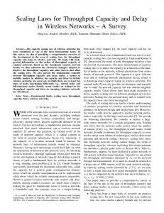
Hence in all cases the outage probability 1 − ps (p) is increasing linearly in p with slope γ . The values of γ are summarized in Table II. The ordering is γ 1/0 > γ 1/1 > γ 0/1 , with equality only if ξ = 0, corresponding to an interferer at distance 0 that causes an outage whenever it transmits, in which case all γ ’s are one. The statement that 1 − exp(−1/ξ) > (1 + ξ)−1 , ξ > 0 is the same as log(1 + ξ) − log ξ < 1/ξ , which is evident from
interpreting the left side as the integral of 1/x from ξ to 1 + ξ and the right side its Riemann upper approximation 1/x times 1. The ordering can also be shown using Jensen’s inequality: γ 1/0 > γ 1/1 since E(exp(−Iθ)) > exp(−θEI) due to the convexity of the exponential. And γ 1/1 > γ 0/1 since E(1 − exp(−Sξ)) < 1 − exp(−ξES) due to the concavity of 1 − exp x. To summarize:
Proposition 1 In the single-interferer case, fading in the desired link is harmful whereas fading in the channel from the interferer is helpful. We also observe that for small ξ , γ 1,1 / γ 0,1 , whereas for larger ξ , γ 1,1 ' γ 1,0 . So if the interferer is relatively close, it does not matter whether the desired link is fading or not. On the other hand, if the interferer is relatively large, it hardly matters whether the interferer’s channel is fading. June 6, 2008
DRAFT
7
The results can be generalized to Nakagami-m fading in a straightforward manner. If the interferer’s channel is Nakagami-m fading, while the desired link is Rayleigh fading, we obtain � � mm 1/m−1 . ps = 1 − p 1 − −1 (ξ + m)m 1/0
As a function of m, this is decreasing for all θ > 0, and in the limit converges to ps
(9)). On the other hand, if the desired link is Nakagami-m, the success probability is � �m mξ −1 m−1 /1 ps = 1−p 1 + mξ −1
(11) as m → ∞ (see
(12)
which increases as m increases for fixed θ > 0 and approaches (10) as m → ∞. The three success probabilities ps (θ) are the complemetary cumulative distributions (ccdf) of the SIR. IV. N ETWORKS
WITH
R ANDOM N ODE D ISTRIBUTION
A. (1, 1, 1): One-dimensional fading random networks with slotted ALOHA Evaluating (5) in the one-dimensional (and noise-free) case yields � � Z ∞ 2p dr = exp(−pθ 1/α C1 (α)) , ps = exp − α /θ 1 + r 0
(13)
p √ where C1 (α) = 2π csc(π/α)/α. For finite C1 , α > 1 is needed. C1 (2) = π , C1 (4) = π/ 2 = C2 (4).
So the spatial contention is γ = θ 1/α C1 (α). For a general d-dimensional network, we may conjecture that γ = θ d/α Cd (α), with Cd = cd (dπ/α) csc(dπ/α) and cd , π d/2 /Γ(1 + d/2) the volume of the d-dim. unit ball. α > d is necessary for finite γ . This generalization is consistent with [13] where it is
shown that for Poisson point processes, all connectivity properties are a function of θ ′ = θ d/α and do no depend on θ in any other way. B. (1, 1, 1): Partially fading random networks with slotted ALOHA If only the desired link is subject to fading (1/0 fading) and α = 4, we can exploit (2), replacing jω by −θ , to get
p1/0 = ŁI (θ) = e−pπΓ(1−2/α)θ s
2/α
.
(14)
For α = 4, p1/0 = ŁI (θ) = e−p s
√
θπ 3/2
.
(15)
So γ = πΓ(1 − 2/α)θ 2/α which is larger than for the case with no fading at all. So, as in the singleinterferer case, it hurts the desired link if interferers do not fade.
June 6, 2008
DRAFT
8
C. (1, 0, 1): Non-fading random networks with α = 4 and slotted ALOHA From [3, Eqn. (21)], I −1 has the cdf FI −1 (θ) = P[1/I < θ] = 1 − ps = erf
√ ! π 3/2 p θ , 2
(16)
which is the outage probability for non-fading channels for a transmitter-receiver distance 1. For the √ spatial contention we obtain γ = π θ, and it can be verified (e.g., by comparing Taylor expansions) that 1 − γp < ps (p) < exp(−γp) holds.
D. (1, 1, 1): Fully random networks with exponential path loss In [14] the authors made a case for exponential path loss laws. To determine their effect on the spatial contention, consider the exponential path loss law exp(−δr) instead of r −α . Following the derivation in [6], we find ∞
� r dr ps = exp −2πp 1 + exp(δr)/θ 0 � � − dilog(θ + 1) = exp −2πp , (17) δ2 Rx where dilog is the dilogarithm function defined as dilog(x) = 1 log t/(1 − t)dt. So γ = −2π dilog(θ + �
Z
1)/δ2 . The (negative) dilog function is bounded by − dilog(x) < log(x)2 /2 + π 2 /6 [15], so � � π π2 2 γ < 2 log (1 + θ) + , δ 3
(18)
indicating that the spatial contention grows more slowly (with log θ instead of θ 2/α ) for large θ than for
the power path loss law. In the exponential case, finiteness of the integral is guaranteed for any δ > 0, in contrast to the power law where α needs to exceed the number of network dimensions. Practical path loss laws may include both an exponential and a power law part, e.g., r −2 exp(−δr). There are, however, no closed-form solutions for such path loss laws, and one has to resort to numerical studies. V. N ETWORKS
WITH
D ETERMINISTIC N ODE P LACEMENT
In this section, we assume that n interferers are placed at fixed distances ri from the intended receiver. A. (0, 1, 1): Fading networks with slotted ALOHA P In this case, ps = P[S > θI] for I = ni=1 Si ri−α and Si iid exponential with mean 1. For general ri
and α, we obtain from ps = E[e−θI ] = ŁI (θ)
ps =
n � Y 1− i=1
June 6, 2008
p � 1 + ξi
(19)
DRAFT
9
where ξi = riα /θ is the effective distance. We find for the spatial contention n X dps (p) 1 γ,− . = dp p=0 1 + ξi
(20)
the other hand, e−pγ is an upper bound, since � n X log 1 − log ps =
(21)
i=1
Since dps /dp is decreasing, ps (p) is convex, so 1 − pγ is a lower bound on the success probability. On
i=1
p 1 + ξi
�
/
n X i=1
−
p . 1 + ξi
The upper bound is tight for small p or ξi large for most i, i.e., if most interferers are far.
B. (0, 1, 1): Infinite regular line networks with fading and ALOHA Here we specialize to the case of regular one-dimensional (line) networks, where ri = i, i ∈ N. For α = 2, we obtain from (4) (or by direct calculation of (20)) � √ 1� √ π θ coth(π θ) − 1 . γ= (22) 2 √ √ Since x coth x − 1 < x < x coth x, this is bounded by (π θ − 1)/2 < γ < π θ/2, with the lower bound being very tight as soon as θ > 1. Again the success probability is bounded by 1 − γp < ps (p) < exp(−pγ), and both these bounds become tight as θ → 0, and the upper bound becomes tight also as θ → ∞.
For α = 4, we first establish the analogous result to (4). Proposition 2 For one-sided infinite regular line networks (ri = i, i ∈ N) with slotted ALOHA and α = 4,
√ where y , πθ 1/4 / 2.
� � cosh2 y(1 − p)1/4 − cos2 y(1 − p)1/4 ps = √ 1 − p (cosh2 y − cos2 y)
Proof: Rewrite (19) as ps =
Qn
(1 + (1 − p)θ/i4 ) i=1 Qn 4 i=1 (1 + θ/i )
.
(23)
(24)
The factorization of both numerator and denominator according to (1 − z 4 /i4 ) = (1 − z 2 /i2 )(1 + z 2 /i2 ) Q √ 2 2 permits the use of Euler’s product formula sin(πz) ≡ πz ∞ ±j((1 − p)θ)1/4 i=1 (1 − z /i ) with z = √ (numerator) and z = ±jθ 1/4 (denominator). The two resulting expressions are complex conjugates, √ √ √ and | sin( jx)|2 = cosh2 (x/ 2) − cos2 (x/ 2).
June 6, 2008
DRAFT
10
The spatial contention is γ=
1 (y − 1)e2y + 4 cos2 y + 4y cos y sin y − 2 − (y + 1)e−2y . 8 cosh2 y − cos2 y
(25)
For y ' 2, the e2y (numerator) and cosh2 y (denominator) terms dominate, so γ ≈ (y − 1)/2 for y > 2. In terms of θ , this implies that
√ γ ≈ πθ 1/4 /(2 2) − 1/2 ,
(26)
which is quite accurate as soon as θ > 1. The corresponding approximation ps ≈ e−p(πθ
1/4
√ /(2 2)−1/2)
.
(27)
can be derived from (23) noting that for y not too small and p not too close to 1, the cosh terms dominate the cos terms and cosh2 (x) ≈ e2x /4, 1 − (1 − p)1/4 ≈ p/4, and (1 − p)−1/2 ≈ ep/2 . For general α, the Taylor expansion of (20) yields ∞ X (−1)i ζ(αi)θ i . γ(θ) = −
(28)
i=1
In particular, γ < ζ(α)θ . Since ζ(x) ' 1 for x > 3, the series converges quickly for θ < 1/2. For θ > 1, it is unsuitable. C. (0, 1, 1): Partially fading regular networks If only the desired link is subject to fading, the success probability is given by ps = e−pθ
thus γ =
Pn
i=1 1/ξi .
Pn
i=1
ri−α
,
(29)
Compared with (20), 1 + ξ is replaced by ξ . So the spatial contention is larger than
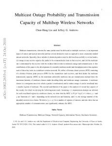
in the case of full fading, i.e., fading in the interferer’s channels helps, as in the single-interferer case. For regular line networks ξi = iα /θ , so γ = θζ(α) and ps = e−pθζ(α) . D. (0, 1, 0): Regular line networks with fading and TDMA If in a TDMA scheme, only every m-th node transmits, the relative distances of the interferers are increased by a factor of m. Fig. 1 shows a two-sided regular line network with m = 2. Since (mr)α /θ = r α /(θm−α ), having every m-th node transmit is equivalent to reducing the threshold θ by a factor mα
and setting p = 1. Proposition 3 The success probability for one-sided infinite regular line networks with Rayleigh fading and m-phase TDMA is: For α = 2: y ps = , sinh y June 6, 2008
√ π θ where y , , m
(30) DRAFT
11
T
... −4
Fig. 1.
...
R −3
−2
−1
1
2
3
4
Two-sided regular line network with TDMA with m = 2, i.e., every second node transmits. The filled circles indicate
the transmitters. The transmitter denoted by T is the intended transmitter, the others are interferers. The receiver at the origin, denoted by R, is the intended receiver. In the one-sided case, the nodes at positions x < 0 do not exist.
and for α = 4: ps =
2y 2 , cosh2 y − cos2 y
πθ 1/4 where y , √ . 2m
(31)
Proof: Apply L’Hˆopital’s rule for p = 1 in (4) and (23) (for α = 2, 4, respectively) and replace θ by θm−α . The following proposition establishes sharp bounds for arbitrary α. Proposition 4 The success probability for one-sided infinite regular line networks, Rayleigh fading, and m-phase TDMA is bounded by α
e−ζ(α)θ/m / ps /
1 . 1 + ζ(α) mθα
(32)
A tighter upper bound is ps /
1+
ζ(α) mθα
1 . 2 + (ζ(α) − 1) mθ2α
(33)
Proof: Upper bound: We only need to proof the tighter bound. Let θ ′ , θ/mα . The expansion of Q∞ ′ α ′ the product (19), p−1 s = i=1 1 + θ /i , ordered according to powers of θ , has only positive terms and starts with 1 + θ ′ ζ(α) + θ ′2(ζ(α) − 1). There are more terms with θ ′2 , but their coefficients are relatively small, so the bound is tight. The lower bound is a special case of (21). Note that all bounds approach the exact ps as θ/mα decreases. Interestingly, for α = 2, 4, the upper bound (32) corresponds exactly to the expressions obtained when the denominators in (30) and (31) are replaced by their Taylor expansions of order 2α. Higher-order Taylor expansions, however, deviate from the tighter bound (33). The success probabilities p′s for two-sided regular networks are obtained simply by squaring the probabilities for the one-sided networks, i.e., p′s = p2s . This follows from the fact that the distances are related as follows: ri′ = r⌈i/2⌉ .
June 6, 2008
DRAFT
12
E. Spatial contention in TDMA networks In order to use the spatial contention framework for TDMA networks, Let p˜ , 1/m be the fraction of time a node transmits. Now dps /d˜ p|p˜=0 = 0 since ps depends on mα rather than m itself. So for TDMA, we define γ,−
dps d(˜ pα ) p˜=0
(34)
and find γ = ζ(α)θ , which is identical to the spatial contention of the ALOHA line network with non-fading interferers. Table III summarizes the results on the spatial contention established in this section.
Uncertainty
Spatial contention γ
Eqn. #dim. Remark
(1, 1, 1)
2πθ 1/α csc(π/α)/α
(13)
1
Two-sided network
2π 2 θ 2/α csc(2π/α)/α √ π 2 θ/2
(6)
2
From [6].
(6)
2
Special case for α = 4
πΓ(1 − 2/α)θ 2/α √ π 3/2 θ √ π θ Pn i=1 1/(1 + ξi ) √ √ π θ coth(π θ)/2 − 1/2 √ ≈ πθ 1/4 /(2 2) − 1/2 Pn i=1 1/ξi
(14)
2
Non-fading interferers
(15)
2
For α = 4 and non-fading interferers
(16)
2
No fading, for α = 4
(20)
d
Deterministic node placement, n nodes
(22)
1
One-sided regular network, α = 2
(26)
1
One-sided regular network, α = 4
(29)
d
Det. node placement, non-fading interf.
(29)
1
Regular network, non-fading interferers
(32)
1
TDMA in one-sided regular networks.
(1, 0, 1) (0, 1, 1)
θζ(α)
(0, 1, 0)
α
ps ' e−ζ(α)θ/m
TABLE III S PATIAL CONTENTION PARAMETERS FOR DIFFERENT TYPES OF SLOTTED ALOHA NETWORKS . F OR COMPARISON , THE TDMA CASE
June 6, 2008
IS ADDED .
“R EGULAR NETWORK ” REFERS TO AN INFINITE LINE NETWORK WITH UNIT
NODE SPACING .
DRAFT
13
VI. T HROUGHPUT
AND
C APACITY
A. (ul , uf , 1): Networks with slotted ALOHA For networks with slotted ALOHA, define the probabilistic throughput as full-duplex: pfT , p ps (p) ;
half-duplex: phT , p(1 − p) ps (p) .
(35)
This is the unconditional probability of success, taking into account the probabilities that the desired transmitters actually transmits and, in the half-duplex case, the desired receiver actually listens. Proposition 5 (Maximum probabilistic throughput in ALOHA networks with fading) Consider a network with ALOHA and Rayleigh fading with spatial contention γ such that ps = e−pγ . Then in the full-duplex case pfT max =
popt = 1/γ ;
1 eγ
(36)
and in the half-duplex case popt
1 1 = + γ 2
�
1−
r
4 1+ 2 γ
�
.
(37)
and phT max
� � γ 1+γ exp − ' , (2 + γ)2 2+γ
(38)
Proof: Full-duplex: popt = 1/γ maximizes p exp(−pγ). Half-duplex: Maximizing log phT (p) yields the quadratic equation p2opt − popt (1 + 2σ) + σ = 0 whose solution is (37). Any approximation of popt
yields a lower bound on phT . Since popt (0) = 1/2, and popt = Θ(γ −1 ) for γ → ∞, a simple yet accurate choice is popt ' 1/(2 + γ) which results in the bound in the proposition. Numerical calculations show that the lower bound (38) is within 1.4% of the true maximum over the whole range γ ∈ R+ . B. (0, 1, 0): Two-sided regular line networks with TDMA Here we consider a two-sided infinite regular line network with m-phase TDMA (see Fig. 1). To maximize the throughput pT , ps /m, we use the bounds (32) for ps . Since the network is now twosided, the expressions need to be squared. Let m ˜ opt ∈ R and m ˆ opt ∈ N be estimates for the true mopt ∈ N. We find �1/α �1/α θζ(α)(2α − 1) d, and the derivative at α = d is 2 for d = 1 and 1 for d = 2. So we have Ropt (α) < α − 2 for d = 2 and Ropt (α) < 2(α − 1) for d = 1.
In the half-duplex case, closed-form solutions are not available. The results of the numerical throughput maximization are shown in Fig. 3, together with the results for the full-duplex case. As can be seen, the maximum throughput scales almost linearly with α−d. The optimum transmit probabilities do not depend strongly on α and are around 0.105 for full-duplex operation and 0.08 for half-duplex operation. The achievable throughput for full-duplex operation is quite exactly 10% higher than for half-duplex operation, over the entire practical range of α. D. (1, 1, 1): Ergodic capacity Based on our definitions, the ergodic capacity can be generally expressed as Z ∞ C = E log(1 + SIR) = − log(1 + θ)dps ,
(45)
0
June 6, 2008
DRAFT
16 12
0.09
Half−duplex Full−duplex
0.08
10
Half−duplex Full−duplex
0.07 Throughput T
θopt
8 6 4
0.06 0.05 0.04 0.03
2
0.02
0 2.5
Fig. 3.
3
3.5
α
4
4.5
5
0.01 2.5
3
3.5
α
4
4.5
5
Left: Optimum threshold θopt for full- and half-duplex operation as a function of α for a two-dimensional network.
Right: Maximum throughput.
where ps (θ) is the ccdf of the SIR. Proposition 7 (Ergodic capacity for (1, 1, 1) networks) Let C be the ergodic capacity of a link in a two-dimensional (1, 1, 1) network with transmit probability p. For α = 4, C = 2ℜ{q} cos(cp ) − 2ℑ{q} sin(cp ) ,
where cp = pC2 (α) and Ei(1, z) = C is lower bounded as C > log 2 ·
where γ(a, x) =
�
R∞ 1
0
(46)
exp(−xz)x−1 dx is the exponential integral. For general α > 2,
c−α/2 γ(1 + α/2, cp ) + p
Rx
q , Ei(1, jcp ) ,
� � √ √ α − 1 exp(− 2cp ) + exp(−cp ) + Ei( 2cp ) , (47) 4 2
�α
ta−1 exp(−t)dt is the lower incomplete gamma function.
The one-dimensional network with path loss exponent α (and cp = pC1 (α)) has the same capacity as the two-dimensional network with path loss exponent 2α. Proof: Let cp , pγθ −2/α = pC2 (α). We have Z 2cp ∞ log(1 + θ)θ 2/α−1 exp(−cp θ 2/α )dθ C= α 0 Z ∞ � � log 1 + tα/2 exp(−cp t)dt . = cp
(48) (49)
0
So, the 2/α-th moment of the SIR is exponentially distributed with mean 1/cp . As a consequence, the capacity of the ALOHA channel is the capacity of a Rayleigh fading channel with mean SIR c−1 p with June 6, 2008
DRAFT
17
an “SIR boost” exponent of α/2 > 1. Note that since a significant part of the probability mass may be located in the interval 0 6 θ < 1, this does not mean that the capacity is larger than for the standard Rayleigh case. This is only true if the SIR is high on average. For general p and α, the integral does not have a closed-form expression. For α = 4, direct calculation of (49) yields C = exp(−jcp ) Ei(1, jcp ) + exp(−jcp ) Ei(1, −jcp ) ,
(50)
which equals (46). To find an analytical lower bound, rewrite (49) as (by substituting t ← t−1 ) Z ∞ log(1 + t−α/2 ) exp(−cp /t) C = cp dt t2 0 and lower bound log(1 + t−α/2 ) by L(t) given by − α2 log t L(t) = log 2 log(2)t−α/2
(51)
√ for 0 6 t < 2/2 √ for 2/2 6 t < 1
(52)
for 1 6 t .
This yields the lower bound (47).
For rational values of α, pseudo-closed-form expressions are available using the Meijer G function. Fig. 4 displays the capacities and lower bounds for α = 2.5, 3, 4, 5. For small cp (high SIR on average), a simpler bound is C>
Z
∞ 1
− log(θ)dps =
α Ei(1, pC(α)) , 2
(53)
To obtain the spatial capacity, the ergodic capacity needs to be multiplied by the probability (density) of transmission. It is expected that there exists an optimum p maximizing the product pC in the case of full-duplex operation or p(1 − p)C in the case of half-duplex operation. The corresponding curves are shown in Fig. 5. Interestingly, in the full-duplex case, the optimum p is decreasing with increasing α. In the half-duplex case, popt ≈ 1/9 quite exactly — independent of α. E. TDMA line networks Proposition 8 (Ergodic capacity bounds for TDMA line networks) For α = 2, � � � � 2m 7ζ(3) 2 2 log m < C < log 1 + π π2 and
June 6, 2008
√ π E SIR = m ; 4
ESIR =
7ζ(3) 2 m . π2
(54)
(55)
DRAFT
18
1 0.5 0
log C
−0.5 α=5
−1 −1.5 −2
α=2.5
−2.5 −3 0
0.2
0.4
0.6
0.8
1
p
Fig. 4. Ergodic capacity for a two-dimensional fading network with ALOHA for α = 2.5, 3, 4, 5 as a function of p. The solid lines are the actual capacities (49), the dashed lines the lower bounds (47).
Fullduplex Operation
Halfduplex Operation
0.2
0.18 0.16 α=5
0.15
0.14
p(1−p)C
pC
0.12 0.1
α=5
0.1 0.08 0.06
0.05
0.04
α=2.5
0.02 0 0
0.2
0.4
0.6 p
Fig. 5.
0.8
1
0 0
α=2.5 0.2
0.4
0.6
0.8
1
p
Spatial capacities for α = 2.5, 3, 4, 5 as a function of p. Left plot: Full-duplex operation. Right plot: Half-duplex
operation. The star marks the optimum p.
June 6, 2008
DRAFT
19
For general α > 1, α
C > eζ(α)/m Ei(1, ζ(α)/mα )
(56)
and ESIR >
1 mα . ζ(α)
(57)
√ Proof: α = 2: Using (45) and (30) and substituting t ← π θ/m yields � �2 ! Z ∞ t cosh t − sinh t mt dt log 1 + C= π sinh2 t 0
(58)
Replacing log(1+x) by log x results in the lower bound which gets tighter as m increases. It also follows √ that π SIR/m is distributed as √ e2t − 2tet − 1 P(π SIR/m < t) = e2t − 1
(59)
from which the moments of the SIR follow. The upper bound in (54) stems from Jensen’s inequality. General α: Use the lower bound (32) on ps and calculate directly. Fig. 6 shows the ergodic capacity for the TDMA line network for α = 2, together with the lower bounds (54) and (56) and the upper bound from (54). As can be seen, the lower bound specific to α = 2 gets tighter for larger m. Using the lower bound (57) on the SIR together with Jensen’s inequality would result in a good approximation C ≈ log(1 + mα /ζ(α)). From the slope of C(m) it can be seen that the optimum spatial reuse factor m = 2 maximizes the spatial capacity C/m for α = 2. For α = 4, m = 3 yields a slightly higher C/m. This is in agreement with the observation made in Fig. 5 (left) that in ALOHA popt slightly decreases as α increases. VII. D ISCUSSION
AND
C ONCLUDING R EMARKS
We have introduced the uncertainty cube to classify wireless networks according to their underlying stochastic processes. For large classes of networks, the outage probability P(SIR < θ) of a unit-distance link is determined by the spatial contention γ . Summarizing the outage results: •
For (1, uf , 1) networks (PPP networks with ALOHA), γ ∝ θ d/α . With Rayleigh fading, ps = exp(−pγ), otherwise ps 6 exp(−pγ).
•
For regular line networks with ALOHA (a class of (0, 1, 1) networks), γ ≈ cθ d/α − 1/2. So, the
regularity is reflected in the shift in γ by 1/2, i.e., γ becomes affine in θ d/α rather than linear. •
Quite generally, with the exception of deterministic networks without fading interferers, γ is a function of θ only through θ d/α (see Table III).
June 6, 2008
DRAFT
20
4 3.5 3
C
2.5 2 1.5 1
Capacity Lower bound 1 Lower bound 2 Upper bound
0.5 0
2
4
6
8
10
m
Fig. 6.
Ergodic capacity for TDMA line network for α = 2 as a function of the reuse parameter m. The solid line is the
actual capacity (49), lower bound 1 and the upper bound are from (54), and lower bound 2 is (56).
•
For regular line networks with m-phase TDMA (a class of (0, 1, 0) networks), ps ≈ exp(−˜ pα ζ(α)θ), where p˜ = 1/m. So the increased efficiency of TDMA scheduling in line networks is reflected in the exponent α of p˜.
The following interpretations of γ = σ −1 demonstrate the fundamental nature of this parameter: •
γ determines how fast ps (p) decays as p increases from 0: ∂ps /∂p|p=0 = −γ .
•
For any ALOHA network with Rayleigh fading, there exists a unique parameter γ such that 1−pγ 6 ps 6 exp(−pγ). This parameter is what we call the spatial contention. From all the networks studied,
we conjecture that this is true for general ALOHA networks. •
•
In a PPP network, the success probability equals the probability that a disk of area γ around the receiver is free from concurrent transmitters. So an equivalent disk model could be devised where p the interference radius is γ/π . For a transmission over distance R, the disk radius would scale to p R γ/π . In full-duplex operation, the probabilistic throughput is pfT = pe−pγ , and popt = min{σ, 1}. So the
spatial efficiency equals the optimum transmit probability in ALOHA, and pfT = σ/e. The throughput is proportional to σ . •
The transmission capacity, introduced in [16], is defined as the maximum spatial density of concurrent
June 6, 2008
DRAFT
21
transmission allowed given an outage constraint ǫ. In our framework, for small ǫ, ps = 1−pγ = 1−ǫ, so p = ǫσ . So the transmission capacity is proportional to the spatial efficiency. •
Even if the channel access protocol used is different from ALOHA, the spatial contention offers a single-parameter characterization of the network’s capabilities to use space.
Using the expressions for the success probabilities ps , we have determined the optimum ALOHA transmission probabilities p and the optimum TDMA parameter m that maximize the probabilistic throughput. Further, ps (θ) enables determining both the optimum θ (rate of transmission) and the ergodic capacity. For the cases where γ ∝ θ d/α , SIRd/α is exponentially distributed. The optimum rates and the throughput are roughly linear in α−d, the spatial capacity is about 2.5× larger than the throughput, and the penalty for half-duplex operation is 10-20%. The optimum transmit probability popt is around 1/9 for both optimum throughput (Fig. 3, right) and maximum spatial capacity (Fig. 4, right). The mean distance to the nearest √ interferer is 1/(2 popt ) = 3/2, so for optimum performance the nearest interferer is, on average, 50% further away from the receiver than the desired transmitter. In line networks with m-phase TDMA, ESIR grows with mα . The results obtained can be generalized for (desired) link distances other than one in a straightforward manner. Many other extensions are possible, such as the inclusion of power control and directional transmissions, as well as node distributions whose uncertainty lies inside the uncertainty cube. ACKNOWLEDGMENT The support of the U.S. National Science Foundation (grants CNS 04-47869, DMS 505624, and CCF 728763) and the DARPA/IPTO IT-MANET program through grant W911NF-07-1-0028 is gratefully acknowledged. R EFERENCES [1] P. Gupta and P. R. Kumar, “The Capacity of Wireless Networks,” IEEE Transactions on Information Theory, vol. 46, pp. 388–404, Mar. 2000. [2] F. Xue and P. R. Kumar, “Scaling Laws for Ad Hoc Wireless Networks: An Information Theoretic Approach,” Foundations and Trends in Networking, vol. 1, no. 2, pp. 145–270, 2006. [3] E. S. Sousa and J. A. Silvester, “Optimum Transmission Ranges in a Direct-Sequence Spread-Spectrum Multihop Packet Radio Network,” IEEE Journal on Selected Areas in Communications, vol. 8, pp. 762–771, June 1990. [4] J.-P. M. G. Linnartz, “Exact Analysis of the Outage Probability in Multiple-User Radio,” IEEE Transactions on Communications, vol. 40, pp. 20–23, Jan. 1992. [5] R. Mathar and J. Mattfeldt, “On the distribution of cumulated interference power in Rayleigh fading channels,” Wireless Networks, vol. 1, pp. 31–36, Feb. 1995. June 6, 2008
DRAFT
22
[6] F. Baccelli, B. Blaszczyszyn, and P. M¨uhlethaler, “An ALOHA Protocol for Multihop Mobile Wireless Networks,” IEEE Transactions on Information Theory, vol. 52, pp. 421–436, Feb. 2006. [7] N. Ahmed and R. G. Baranjuk, “Throughput Measures for Delay-Constrained Communications in Fading Channels,” in Allerton Conference on Communication, Control and Computing, (Monticello, IL), Oct. 2003. [8] S. B. Lowen and M. C. Teich, “Power-law Shot Noise,” IEEE Transactions on Information Theory, vol. 36, pp. 1302–1318, Nov. 1990. [9] E. S. Sousa, “Interference Modeling in a Direct-Sequence Spread-Spectrum Packet Radio Network,” IEEE Transactions on Communications, vol. 38, pp. 1475–1482, Sept. 1990. [10] M. Hellebrandt and R. Mathar, “Cumulated interference power and bit-error-rates in mobile packet radio,” Wireless Networks, vol. 3, no. 3, pp. 169–172, 1997. [11] J. Ilow and D. Hatzinakos, “Analytical Alpha-stable Noise Modeling in a Poisson Field of Interferers or Scatterers,” IEEE Transactions on Signal Processing, vol. 46, no. 6, pp. 1601–1611, 1998. [12] M. Zorzi and S. Pupolin, “Optimum Transmission Ranges in Multihop Packet Radio Networks in the Presence of Fading,” IEEE Transactions on Communications, vol. 43, pp. 2201–2205, July 1995. [13] M. Haenggi, “A Geometric Interpretation of Fading in Wireless Networks: Theory and Applications,” IEEE Trans. on Information Theory, 2008. Submitted. Available at http://www.nd.edu/∼mhaenggi/pubs/tit08b.pdf. [14] M. Franceschetti, J. Bruck, and L. Schulman, “A Random Walk Model of Wave Propagation,” IEEE Transactions on Antennas and Propagation, vol. 52, pp. 1304–1317, May 2004. [15] M. Hassani, “Approximation of the Dilogarithm Function,” Journal of Inequalities in Pure and Applied Mathematics, vol. 8, no. 1, 2007. [16] S. Weber, X. Yang, J. G. Andrews, and G. de Veciana, “Transmission Capacity of Wireless Ad Hoc Networks with Outage Constraints,” IEEE Transactions on Information Theory, vol. 51, pp. 4091–4102, Dec. 2005.
June 6, 2008
DRAFT
Ergodic Capacity and Lower Bound for
α=4
10
8
6
C
4
2
0 0
0.2
0.4
0.6
p~
0.8
1.0
20 18 α=2
16 14
m
12 10 8 6 4 2 0 0
5
10 Θ [dB]
15
20
1 Exact expression Approximation
0.9 0.8 0.7
ps
0.6
Θ=0dB
0.5 0.4 Θ=10dB
0.3 0.2 0.1 0 0
Θ=20dB 0.2
0.4
0.6 p
0.8
1
1 0.9
ξ=2
0.8 0.7 ξ=1/4
ps
0.6 0.5 0.4 0.3 0.2 0.1 0 0
Exact (fading) Approx. (fading) Exact (part. fading) 0.2
0.4
0.6 p
0.8
1
success probability ps
1
0.8
0.6 ξ=2
0.4
0.2
0 0
ξ=1/3
1/1 1/0 0/1 0/0 0.2
0.4 0.6 transmit probability p
0.8
1
α=2 0.5 Theoretical optimum For integer m
0.45 0.4 Throughput g(Θ)
0.35 0.3 0.25 0.2 0.15 0.1 0.05 0 0
5
10 Θ [dB]
15
20