Circuit Logic Gate. A logic gate is an elemantary building block of a digital circuit.
Most logic gates have two inputs and one output. Every terminal is in one of the ...
Outline Here we introduced (1) basic circuit for logic and (2)recent nano-devices, and presented (3) some practical issues on nano-devices.
Circuit Logic Gate A logic gate is an elemantary building block of a digital circuit. Most logic gates have two inputs and one output. Every terminal is in one of the two binary conditions low (0) or high (1), represented by different voltage levels. In most logic gates, the low state is zero volts (0 V), while the high state is five volts (+5 V). There are seven basic logic gates: AND, OR, XOR, NOT, NAND, NOR, and XNOR. The AND gate is so named because, if 0 is called "false" and 1 is called "true," the gate acts in the same way as the logical "and" operator. The following illustration and logic table show the circuit symbol and logic construction for an AND gate. The output is "true" when both inputs are "true." Otherwise, the output is "false."
AND
A
B
Y
0
0
0
0
1
0
1
0
0
1
1
1
The OR gate behaves after the fashion of the logical inclusive "or." The output is "true" if either or both of the inputs are "true." If both inputs are "false," then the output is "false."
OR
A
B
Y
0
0
0
0
1
1
1
0
1
1
1
1
A logical inverter, sometimes called a NOT gate to differentiate it from other types of electronic inverter devices, has only one input. It reverses the logic state.
NOT
A
Y
0
1
1
0
To make the XOR gate we need 3 gates. The XOR (exclusive-OR) gate acts in the same way as the logical "either/or." The output is "true" if either, but not both, of the inputs are "true." The output is "false" if both inputs are "false" or if both inputs are "true." Another way of looking at this circuit is to observe that the output is 1 if the inputs are different, but 0 if the inputs are the same.
XOR
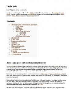
The term ‘Gate’ is used to describe the members of a set of basic electronic components which, when combined with each other, are able to perform complex logical and arithmetic operations. 'Gates' are the physical realization of the simple Boolean expressions.
Adder
half adder
Now let’s talk about “Adder”. Adders are combinations of logic gates that combine binary values to obtain a sum. They are classified according to their ability to accept and combine the digits (quarter adders, half adders, and full adders ). This is half adders. It’s designed to combine two binary digits and produce a carry. We can construct every functional circuit blocks with elementary logic gates.
NOT Gate The simplest form of an MOS logic circuit is an inverter, as shown in left figure. It consists of a “load” resistance R called the pull-up resistor and pull-down transistor connected in series between supply voltage Vdd and ground.
Transfer Characteristic Real gate
We note that the operating point moves through the curve as Vin is increased from 0 to Vdd, which yields the voltage transfer curve for an inverter, shown in figure.
NAND gate The basic NOR and NAND logic function can be implemented by replacing the transistor of the invertor by parallel and series connection of transistor as shown in left figure.
The truth table show that the input A and B are applied via poly-silicon lines ; the output can be taken in diffusion from the source side of pull-up or via polysilicon from the gate side. A
B
Y
0
0
1
0
1
1
1
0
1
1
1
0
For the NAND gate if input A and B are both high, the pull-down path will be closed and the output will be pulled low.
Nanoscale Devices MOSFET The metal-oxide semiconductor (MOS) field-effect transistor (FET) exhibits an extremely high input resistance. In MOSFET the channel current is controlled by a voltage applied at a gate electrode which is isolated from the channel by an insulator. MOSFET ( N-MOS )
MOSFET ( N-MOS )
p-
N-MOS
P-MOS
There are two basic types of MOS transistors : the nchannel and the p-channel.
The structure of an n-channel MOS transistor is shown in figure. It consists of two islands of n-type diffusions embedded in a p-type substrate, which are connected via metal or poly-silicon to external conductors called source and drain. On the surface a thin layer of silicon dioxide is formed and on top of this a conducting material made of poly-silicon called a gate is deposited.
If the substrate material is n-type and the diffused islands are p-type, it will be p-channel MOS transistor
The terminal characteristics of the device are given by drain-to-source current Ids against drain-to-source voltage Vds for different values of gate-to-source voltage Vgs. All voltages are referenced with respect to the source voltage, which is assumed to be at ground potential.
Vds
Ids
-5
Saturatoin region Linear region
Vgs = 5 V Vgs = 4 V Vgs = 3 V
5 V ds (a) n-channel transistor
Vgs = -3 V Vgs = -4 V Vgs = -5 V Ids (b) p-channel transistor
CMOS In CMOS, both p- and n-channel transistors are used. The silicon substrate is an n-type, in which a p-type “well” is created by diffusion. Ths n-channel transistors are created in the p-well region. The p-channel transistors are made in the n-substrate. The basic structure of the p-well CMOS inverter is shown below.
Input Vdd
Vss
Out
P-well p-type n-type
When the input voltage Vin = 0, the gate of the p-channel transistor is at Vdd below the source potential, that is, Vgs = -Vdd, which will turn on this transistor, offering a lowresistance path to load capacitance C, which will be charged up to Vdd. No current flows through the n-channel transistor, which is turned off since Vgs = 0 for this transistor. If the input voltage is now increased to its threshold voltage and then to Vdd, the n-channel transistor will conduct while the p-channel transistor is turned off, discharging the load capacitance C to ground potential. The current flows until the output node reaches Vdd(when charging) or ground (when discharging), the transistors to provide either the carge or the discharge current. Vdd
Vin
Vout C
Vss
Since both the transistors are enhancement-mode transistors, here we used the symbols Vgs, Vth, and Vds as before with a letter “p” or “n” attached to the end of the subscript to indicate whether the quantity refers to the p-channel or nchannel device.
Referring all the voltages to Vss = 0 (the substrate voltage of the n-device), we can write Vgsn = Vin Vdsn = Vout Vgsp = Vin - Vdd Vdsp = Vout – Vdd The drain-to-source currents for the n-channel and p-channel transistors are plotted below. Idsp
Idsn P-channel
0
n-channel
Vdd
Vout Vdd I
0< Vin