Lecture 21: 04/21/03 A.R. Neureuther. Version Date 04/19/03. EECS 42 Intro.
electronics for CS Spring 2003. CMOS Logic Gate: Example Inputs. A. B. C. A. B.
C.
EECS 42 Intro. electronics for CS Spring 2003
Lecture 21: 04/21/03 A.R. Neureuther
EECS 42 Intro. electronics for CS Spring 2003
Lecture 21: 04/21/03 A.R. Neureuther
Version Date 04/19/03
Version Date 04/19/03
EECS 42 Introduction to Electronics for Computer Science
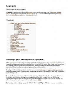
Logic Gate Propagation Delay: Initial State VDD
Andrew R. Neureuther
A
Lecture # 21 Clock Operation of Latches
RU
RU
Handout of Monday Lecture.
A) 2nd Midterm Returned B) Latch circuit to hold/release signals C) Cascade CMOS elements with latches
The initial state depends on the old (previous) inputs.
RU
C
B
Example: A=0, B=0, C=0 for a long time.
VOUT
These inputs provided a path to VDD for a long time and the capacitor has precharged up to VDD = 5V. COUT = 50 fF
RD RD
B
A
RD
http://inst.EECS.Berkeley.EDU/~ee42/
C
Copyright 2001, Regents of University of California
EECS 42 Intro. electronics for CS Spring 2003
The equivalent resistance of the pull-down or pullup network for the transient phase depends on the new (present) input state.
Copyright 2001, Regents of University of California
Lecture 21: 04/21/03 A.R. Neureuther
EECS 42 Intro. electronics for CS Spring 2003
Lecture 21: 04/21/03 A.R. Neureuther
Version Date 04/19/03
Version Date 04/19/03
Game Plan 04/21/03
Logic Gate: Worst Case Scenarios
Last Week: Logic Delay; resistor model, CMOS operation and delay
VDD
Monday 4/14/03: R 2nd Midterm returned R CMOS Latch and use in logic cascade
What combination of previous and present logic inputs will make the Pull-Up the fastest?
RU A RU
RU
Wednesday 04/09/03: R Clocked Latch and Timing Diagram R Latency and Throughput R Feedback in logic to produce memory
C
B
VOUT
RD
B
A
RD C
Problem set #10 for 4/303: Logic Delay; Cascade; Latches and Clock frequency Copyright 2001, Regents of University of California
EECS 42 Intro. electronics for CS Spring 2003
What combination of previous and present logic inputs will make the Pull-Down the fastest?
RD
Next (13th) Week: Diodes and MOS Devices
What combination of previous and present logic inputs will make the Pull-Up the slowest?
Copyright 2001, Regents of University of California
Lecture 21: 04/21/03 A.R. Neureuther
EECS 42 Intro. electronics for CS Spring 2003
Lecture 21: 04/21/03 A.R. Neureuther Version Date 04/19/03
Logic Gate Cascade
CMOS Logic Gate: Example Inputs VDD PMOS A conducts; B and C Open
A
To avoid large resistance due to many gates in series, logic functions with 4 or more inputs are usually made from cascading two or more 2-4 input blocks. VDD
Output is High B
B1
VOUT 1 B2
NMOS B and C conduct; A open
A A1
C Logic is Complementary and produces F = 0 Copyright 2001, Regents of University of California
B2 = VOUT 1 The four independent input are A1, B1, A2 and C2.
A2
=0
VOUT B
VDD
A1
C
Slowest overall?
COUT = 50 fF What combination of previous and present logic inputs will make the Pull-Down the slowest?
Version Date 04/19/03
A=0 B=1 C=1
Fastest overall?
C2 B2
B1
A2 50 fF
C2
VOUT 2
A2 high discharges gate 2 without even waiting for the output of gate 1.
50 fF
C2 high and A2 low makes gate 2 wait for Gate 1 output
Copyright 2001, Regents of University of California
1
EECS 42 Intro. electronics for CS Spring 2003
Lecture 21: 04/21/03 A.R. Neureuther
EECS 42 Intro. electronics for CS Spring 2003
Lecture 21: 04/21/03 A.R. Neureuther
Version Date 04/19/03
Version Date 04/19/03
Latch Work Best In Pairs
Data Synchronization problem • Combinatorial logic gates can give incorrect answers prematurely and may take several gate propagation delays produce an answer. • Clocks (signals as to when to proceed) and latches (which capture and hold the correct outputs) can provide synchronization.
VDD
VDD φ
VOUT_EXT
VOUT_INT
VIN
The first stage operates while the clock is low and inverts and amplifies the arriving signal and charges or discharges CL1.
φ
CL2
CL1 φ
φ
The second stage operates while the clock is high and inverts the signal on CL1 to charge or discharge CL2 and downstream logic gate inputs.
Clock
1 time
0 Copyright 2001, Regents of University of California
EECS 42 Intro. electronics for CS Spring 2003
Copyright 2001, Regents of University of California
Lecture 21: 04/21/03 A.R. Neureuther
EECS 42 Intro. electronics for CS Spring 2003
Lecture 21: 04/21/03 A.R. Neureuther
Version Date 04/19/03
Version Date 04/19/03
A Double Latch is an Edge-Triggered D Type Flip-Flop
Latch Controlled by a Clock VDD φ
When the clock φ is high its complement φ is low and the inverter operates.
VOUT VIN
COUT φ
To synchronize the data the clock remains low until the data is correct at all locations on the chip. When the clock goes high the inverse of the data is passed.
VDD
VDD
An inverter with clocked devices in series can form a latch.
φ
VOUT
VIN
VOUT
Note that this circuit is not fooled by noise on the input and makes its decision on the rising edge of the clock (edge-triggered).
CL2
CL1 φ
φ
Copyright 2001, Regents of University of California
EECS 42 Intro. electronics for CS Spring 2003
During the low part of the clock cycle this circuit records the input value and when the clock goes high drives VOUT 2 to the voltage level that arrived. (This is the classic function of a D flip-flop.)
φ
Copyright 2001, Regents of University of California
Lecture 21: 04/21/03 A.R. Neureuther
EECS 42 Intro. electronics for CS Spring 2003
Lecture 21: 04/21/03 A.R. Neureuther
Version Date 04/19/03
Clock Signal Definitions Rising-edge Clock
Version Date 04/19/03
Example of Circuits to Integrate with Latches
Falling-edge
VDD
VDD A2
A1
1
B1
0 τ P HIGH τLOW
time A1
CG1 B1
B2 VOUT-C1
C1
VOUT-C2 A2
C2
CG2
B2
Period
Period =P = τHIGH + τLOW
Gate 1
Gate 2
Frequency = 1/P = 1/(τHIGH + τLOW) Duty Cycle = (τHIGH)/(τHIGH + τLOW) Copyright 2001, Regents of University of California
Copyright 2001, Regents of University of California
2
EECS 42 Intro. electronics for CS Spring 2003
Lecture 21: 04/21/03 A.R. Neureuther Version Date 04/19/03
Latch Implementation: Lumped VDD
VDD φ
φ
VIN-L0
B1
φ
VIN-L0
CG2
A2 C2 B2
CL2
CL1 φ
φ
Gate 2
Gate 1
VOUT-L0
VMID-L0
VOUT-C1
C1
B1
Latch 0
φ
B2
VOUT-C2
CG1
CL2 A1
CL1 φ
φ
A2
A1
VOUT-L0
VMID-L0
VDD
VDD
VDD
VDD
Latch 1
Copyright 2001, Regents of University of California
EECS 42 Intro. electronics for CS Spring 2003
Lecture 21: 04/21/03 A.R. Neureuther Version Date 04/19/03
Latch Operation: Lumped Latch 0
φ
B1
φ
B2
VIN-L0
C2 B2
Clock
CL2
CL1 φ
φ
Low
High
Low
VOUT-L0
VMID-L0
CG2
A2
B1
φ
VOUT-C1
C1
VOUT-C2
CG1
CL2 A1
CL1 φ
φ
A2
A1
VOUT-L0
VMID-L0
VDD
VDD
VDD
VDD
φ
VIN-L0
Latch 1
Gate 2
Gate 1
VDD
VDD
High
τHIGH = τL_EXT + τGATE1 + τGATE2
1
τLOW = τL_INT
time
0
Copyright 2001, Regents of University of California
EECS 42 Intro. electronics for CS Spring 2003
Lecture 21: 04/21/03 A.R. Neureuther Version Date 04/19/03
Latch Implementation: Pipelined Latch 0
φ VIN-L0
VOUT
L0
φ
A1
-L0
B1
VOUT-
VIN-L0
CL1 φ
φ
CA1 L2
CG1 B1
φ
A2 VOUT
B2 C1
-L0
L0
C2
VDD
φ VMID-
Latch 2
Gate 2
VDD
VDD
VDD
φ VMID-
Latch 1
Gate 1
VDD
VDD
CL2 B2
φ
φ
VIN-L0 VOUT-C1
VMID-
VOUTL0
L0
A2 CL1 φ
VDD
VDD
C 2
CG2 CL1 φ
CL2
φ
Copyright 2001, Regents of University of California
3