[6] Fortuna Z., Macukow B., W¹sowski J., Metody numeryczne. ... [14] Wierzbicki A., Szymanowski J., Findeisen W., Teoria i metody obliczeniowe optymalizacji.
AUTOMATYKA 2008 Tom 12 Zeszyt 2
Jerzy Baranowski*
Output Collocation Method for Continuous State Estimation from Discrete Output Measurements in Linear Dynamical Systems** 1. Introduction One of the typical problems arising in the control of dynamical systems is the lack of complete state measurement. Moreover, in some situations, the system output is not measured continuously but only at chosen moments. Many such situations (continuous dynamical systems with discrete output, but not necessarily discrete control) can be found in practical applications. Most typical examples are available in chemical industry (processes of polymerization, continuously stirred chemical reactors), temperature and heating control problems, mechatronic systems using cameras for measurement, etc. The problem arises in any situation when continuous measurement of the system outputs is either impossible or impractical. The author’s previous works ([1–3, 5, 10]) the estimation of continuous state from sampled output was considered and several different methods were introduced, both for linear and nonlinear systems. This problem – Continuous State Estimation from Discrete Output Measurements (CSEDOM) can be formulated as follows. We consider a dynamical system: x& (t ) = f ( x(t ), u (t ))
(1)
where x (t ) ∈ ¡ n is a system state, and u (t ) ∈ ¡ r is a control signal. We will assume that u(t) is continuous for all t. We consider an output of system (1) y (t ) = h( x(t ))
(2)
and that it is available only for t ∈ {t0 , t1 , t2 , ...}, for clarity we will assume that output values are scalar and ti = ih where h > 0 is a fixed value (a discretisation step). * Institute of Automatics, AGH University of Science and Technology, Krakow ** Work financed by state science funds for 20082010 as a research project. Contract no. N N514 417734
183
184
Jerzy Baranowski
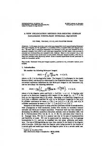
The goal of CSEDOM is to estimate the values of state x(t) with an estimate xˆ(t ) for t ∈ [ti , ti + 1] using the information regarding the output for t ≤ ti and the control for t ≤ ti+1. Such problem can be solved with an algorithm (see for example [5]) 1. PREDICTION STEP Solve the differential equation x& (t ) = f ( x(t ), u (t )) for t ∈ [ti , ti + 1] using xˆ(ti ) as an initial condition. 2. CORRECTION STEP Using the measurements of y(t) and u(t) for t ≤ ti +1 estimate the value of xˆ(ti +1 ). 3. Set i = i + 1 and go back to step 1. The concept of this algorithm is relatively simple – see Figure 1. However the main problem is the choice of the estimation method used in the correction step. In this paper, an approximate approach will be considered, description of which will follow. Other approaches such as a discrete Luenberger observer, exact discrete estimation and least squares discrete estimation were introduced in [10] and their comparison with interpolation based approximate methods was considered in [4].
Fig. 1. Illustration of the idea of CSEDOM a prediction is followed by a correction. xm denotes one of the estimated state variables solid line is the true value of the state, dotted line is the continuous estimate, o is a value obtained from the correction step
Remark 1 It should be noted, that the strengths of this approach are especially visible, when the measurements are available rarely (output sampling frequency is low). Such situations arise
Output Collocation Method for Continuous State Estimation...
185
in the examples listed in the beginning. Otherwise either discretisation of the system or even ignoring the output discrete character could lead to better results. Remark 2 The control signal u(t) is assumed to be continuous for all t. This assumption was made for the simplicity of the following approximate estimation algorithm presentation. Algorithm can easily handle control discontinuities however in that situation the approximation nodes choice would be influenced by the discontinuities location. The method for choosing appropriate nodes is purely algorithmic, and does not influence the main idea of the introduced method, which is the main focus of this paper. Remark 3 Linear systems are considered in this paper, so (1) will take a following form: x& (t ) = Ax(t ) + Bu (t )
and (2) will become y(t) = Cx(t).
2. Approximate estimation In previous works ([1–3]), the concept of approximate continuous state estimation was presented. The main idea was to use well-known continuous state estimation methods, but instead of applying them to the system output, which is available only on discrete time instances, they would be used with a continuous function approximating the output. The obvious merit of this approach is that there is no need for discrete system model which for high order linear systems can be difficult to obtain. One of such methods is an asymptotic observer
xˆ� (t ) = Axˆ (t ) + Bu(t ) + G ( y(t ) − Cxˆ )
(3)
where G is chosen in such way that the error of estimation e(t ) = x(t ) − xˆ
(4)
will behave as follows e(t ) → 0 when t → ∞
(5)
It should be noted that (5) is equivalent to Reλ(A – GC) < 0. The main idea of approximate estimation is to choose a window of output samples and create yˆ that approximates y over this window. Then use it in (3) to find an approximate state estimate. The choice of such approximation is however a difficult matter.
186
Jerzy Baranowski
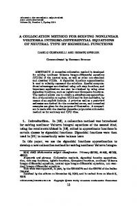
2.1. Polynomial and spline interpolation It is obvious, that to approximate the discrete output with a continuous function, at least few output samples have to be used. In author’s previous works ([1, 3]) the third order polynomial interpolation was used. Benefits of such choice are multiple. Approximation is very regular, simple to compute and can be used in analytical computations (for example for an analytical solution of approximate min L2 approximation which was consi-dered in author’s previous works). Moreover, only 4 output samples are required. Unfortunately, classical polynomial interpolation also has its flaws. First of all, it is difficult or even impossible to use previously obtained polynomials on the new measurement window. As it can be seen in the Figure 2, polynomial interpolation, effective with outputs of aperiodic systems (or at least systems which continuous output contains only low frequencies), completely fails completely with strongly oscillatory systems. More details regarding application of polynomial interpolation in CSEDOM are in [1].
Fig. 2. System output, its approximation (via output collocation method) and interpolation
A standard method of a more advanced interpolation are cubic splines [6]. They also provides good regularity and is more flexible to handle higher output frequencies. Spline implementations are widely available (for example in MATLAB). Splines however, require more output samples than standard interpolation, to provide any of their benefits. There has to be a compromise in the measurement window lenght between an accuracy and simplicity (and speed) of computation. It should be also noted that interpolation methods are sensitive to disturbances. Interpolation of output samples that are measured with an error, would cause the interpolating function to be far from the system output.
Output Collocation Method for Continuous State Estimation...
187
2.2 Output collocations In this paper, we introduce a new method with the working name output collocations (because it was inspired by collocation methods for solving differential equations, see for example [7]). What is most important, is that this algorithm is directly tied with a CSEDOM problem and the algorithm presented in the introduction. Moreover the algorithm presented here has arbitrarily chosen parameters. These parameters however can be easily changed to improve the methods effectiveness in certain cases. One of the disadvantages of interpolating polynomials (in Lagrange sense [12]) was that they did not use the information that the system output is a function of a differential equation solution. Moreover, the form of this equation did not influence the shape of interpolation polynomial. One should see, that with (1) (its linear version) we can present a formula for the output derivative: y ′(t ) = Cx& = C ( Ax(t ) + Bu (t ))
(6)
If we would knew the derivative, we could formulate some kind of Hermite interpolation problem. The difficulty is that the derivative of (6) requires the knowledge of ?x(t), knowledge which by itself is the goal of CSEDOM problem. We can, however, use the estimate xˆ(t ) ? that was computed from the last iteration of main algorithm. The cost of it is the introduction of estimation error into the approximation process. To sum up, we can introduce additional information regarding the approximated function – its derivative – but at the same time introducing the estimation error. Moreover, it should be noted that the output measurements would be usually biased with some kind of disturbance, in other words they would differ from the actual output. We can conclude then, that interpolation is not the best approach, to approximate the output. In addition to that, we should consider what kind of regularity we require from the approximated output. Its continuity would usually be enough. It is necessary, because only then continuous estimation methods on the entire approximation window can lead to meaningful results. On the other hand, we would require a rather large amount of flexibility in construction of such approximation. Such flexibility at the cost of lower regularity is provided by splines.
We consider an approximation of output that: is a third order spline function on 4 output samples (nodes) a minimal number of samples for a third order polynomial, is continuous, fits the output measurements in the least squares sense, its derivatives (in appropriate cases one sided) fit the estimated output derivatives in the least squares sense at points of measurements and at the points in the middle of interval between the measurements.
Listed conditions form a constrained quadratic programming problem. The following theorem can be proven.
188
Jerzy Baranowski
Theorem 1 Let system (1) output samples y(tj) are known for j = 0, 1, 2, 3 and the output derivatives yˆ ′(t ) are estimated for k = 0, 1/2, 1, … 3. Then there exists an approximating function on the interval [t0, t3] that: is a third order spline function on nodes tj for j = 0, 1, 2, 3, is continuous, fits the output measurements in the least squares sense, its derivatives (in appropriate cases one sided) fit the estimated output derivatives in the least squares sense at tk where k = 0, 1/2, 1,
3. Also such function is unique. Proof For the proof we will formulate the output collocation method as a constrained quadratic programming problem and we will show that it is convex. Because three polynomials will be needed, their coefficients will be denoted as ai where i = 1, 2, … 12. We asume that output samples are available for tj where j = 0, 1, 2, 3 and output derivatives (computed with use of (6) and information from previous iteration) will be denoted as yˆ ′(t ) with k = 0, 1/2, 1, … 3. We need to consider fitting of the measurements by the approximating function: a1t03 + a2 t02 + a3t0 + a4 − y (t0 ) = 0 a1t13 + a2 t12 + a3t1 + a4 − y (t1 ) = 0 a9 t23 + a10t22 + a11t2 + a12 − y (t2 ) = 0
(7)
a9 t33 + a10t13 + a11t3 + a12 − y (t3 ) = 0
and fitting the derivatives: 3a1t02 + 2a2t0 + a3 − yˆ ′(t0 ) = 0 2 3a1t1/ 2 + 2a2 t1/ 2 + a3 − yˆ ′(t1/ 2 ) = 0
3a1t12 + 2a2t1 + a3 − yˆ ′(t1 ) = 0 3a5t12 + 2a6 t1 + a7 − yˆ ′(t1 ) = 0 2 3a5t3/ 2 + 2a6t3/ 2 + a7 − yˆ ′(t3 / 2 ) = 0
3a5t22 + 2a6 t2 + a7 − yˆ ′(t2 ) = 0 3a9 t22 + 2a10 t2 + a11 − yˆ ′(t2 ) = 0 3a9 t52/ 2 + 2a10 t5 / 2 + a11 − yˆ ′(t5 / 2 ) = 0 3a9 t32 + 2a10 t3 + a11 − yˆ ′(t3 ) = 0
(8)
Output Collocation Method for Continuous State Estimation...
189
Moreover, we will require continuity of the approximating function. It can be seen that following constraints cannot be violated:
a1t13 + a2t12 + a3t1 + a4 − a5t13 − a6t12 − a7 t1 − a8 = 0 a5t23 + a6t22 + a7 t2 + a8 − a9t23 − a10t22 − a11t2 − a12 = 0
(9)
We want to fulfil (7) and (8) in a least squares sense. That is why we can represent equations in (7) as minimisation problems (below an example for first equation of (7)): T min a[1..4] B1 (t0 ) a[1..4] − 2 y (t0 )c1 (t0 ) a[1..4] + y (t0 ) 2
(10)
⎡α6 ⎢ ⎢ α5 B1 (α ) = ⎢ ⎢α4 ⎢ 3 ⎢⎣ α
(11)
a[1..4]
where α5
α4
α3 ⎤ ⎥ α3 α 2 ⎥ ⎥ α2 α ⎥ ⎥ α 1 ⎥⎦
α4 α3 α2
and c1 (α ) = [α3
α2
(12)
α 1]
Equations in (8) are then represented in a similar way (first equation of (8)): T B2 (t0 )a[1..4] − 2 y (t0 )c2 (t0 )a[1..4] + yˆ ′(t0 )2 min a[1..4]
(13)
⎡9α 4 ⎢ ⎢6α3 B2 (α ) = ⎢ ⎢3α 2 ⎢ ⎣0
(14)
a[1..4]
where
6α3
3α 2
4α 2
2α
2α 0
1 0
0⎤ ⎥ 0⎥ ⎥ 0⎥ ⎥ 0⎦
and c2 (α ) = [3α 2
2α 1 0]
(15)
All these minimisation problems as in (10) and (13) can be collected into (constant parts are omitted): min a T * a + + a a
s.t. /a = 0
(16)
190
Jerzy Baranowski
with ⎡ B∗ ⎢ * = 0⎢ 0 ⎢ ⎣0
0 B2 (t1 ) + B2 (t3 / 2 ) + B2 (t2 ) 0
0 ⎤ ⎥ 0 ⎥ ⎥ B∗∗ ⎦
(17)
B∗ = B1 (t0 ) + B1 (t1 ) + B2 (t0 ) + B2 (t1/ 2 ) + B2 (t1 ) B∗∗ = B1 (t2 ) + B1 (t3 ) + B2 (t2 ) + B2 (t5 / 2 ) + B2 (t3 ) + = −2 ⎡⎣C ∗
yˆ ′(t1 )c2 (t1 ) + yˆ ′(t3 / 2 )c2 (t3 / 2 ) + yˆ ′(t2 )c2 (t2 ) C ∗∗ ⎤⎦
(18)
C ∗ = y (t0 )c1 (t0 ) + y (t1 )c1 (t1 + yˆ ′(t0 )c2 (t0 ) + yˆ ′(t1/ 2 )c2 (t1/ 2 ) + yˆ ′(t1 )c2 (t1 ) C ∗∗ = y (t2 )c1 (t2 ) + y (t3 )c1 (t3 + yˆ ′(t2 )c2 (t2 ) + yˆ ′(t5 / 2 )c2 (t5 / 2 ) + yˆ ′(t3 )c2 (t3 ) 0 ⎤ ⎡ c (t ) −c1 (t1 ) /=⎢ 1 1 c1 (t2 ) −c1 (t2 ) ⎥⎦ ⎣ 0
(19)
It can be easily verified that matrices B1 and B2 are semi-positive definite and that the matrix (17) is a linear combination with positive coefficients of semi-positive definite matrices. This leads to the conclusion that * is semi-positive definite and that the minimisation problem (16) is convex (see [11, 14]). o Remark 4 It should be also noted that formulation (16) of the output collocation problem provides a constructive method for its solution. It can be obtained through solving of the following system of linear equations
⎡ * /T ⎤ ⎡ a ⎤ ⎡ −+ ⎤ ⎢ ⎥⎢ ⎥ = ⎢ ⎥ ⎢⎣ / 0 ⎥⎦ ⎣μ ⎦ ⎣ � ⎦
(20)
where μ is a vector of Lagrange multipliers associated with equality constraints. Because of theorem 1, (18) has a unique solution.
2.3. Remarks regarding implementation To implement the output collocation method for approximate continuous state estimation, one should consider several aspects. First, it should be noted, that the continuous observer (3) used with the approximating function yˆ allows to obtain the state estimate at the end of the measurement window used for approximation. However, for the next iteration
Output Collocation Method for Continuous State Estimation...
191
and estimation of derivatives one needs an initial condition at the beginning of next window (usually shifted by one sample). There are several ways to solve the problem: 1. Use the estimated state at the end of the window as a terminal condition solve the system equation (1) backwards in time. In this way most recent information would be used to estimate the output derivatives. 2. Other method is to use the observer not with the entire approximating function (the entire window) but only with the part that was added by window shifting. Initial condition for the observer would be the last estimate, and derivatives would be estimated using the state estimates from the observer. 3. Third way, is to use the value of estimate from previous iteration corresponding to the beginning of the new measurement window as an initial condition for the observer and for system (1) for computation of the derivatives. Another aspect that has to be considered is conditioning of the system (18). It is obvious that because the matrices in that system are time-dependent, conditioning of the system gets worse as time passes. However, this can be avoided if the problem is solved from some low values of t but then shifted in time domain. That approach helps avoiding the problems with inverting the matrix of (18).
3. Numerical experiments For the tests of approximate estimation method we will consider two dynamical systems.
3.1. Approximation of a parabolic system The system described in Figure 3 is modelled by the standard 1-D heat equation (parabolic partial differential equation with Neumanns boundary conditions). ∂T (t , z ) ∂ 2T ( t , z ) = π−2 + b( z )u (t ), ∂t ∂z 2 ∂T (t , z ) ∂z
z =0
=
∂T (t , z ) ∂z
z =1
= 0,
with distributed control and observation. For numerical tests we will use its 7th order finite dimensional approximation. For details on such approximations see [4, 9].
Fig. 3. Distributed control and observation of the 1-D heating process
192
Jerzy Baranowski
3.2. Oscillation of a 3-storey building during an earthquake Such system can be described by a second order differential equation (with a dimension 3). Ex&&(t ) + Ax(t ) = Bz&&(t ), where: ⎡m 0 0 ⎤ E = ⎢⎢ 0 m 0 ⎥⎥ , ⎣⎢ 0 0 m ⎦⎥ ⎡ 2k A = ⎢⎢ −k ⎣⎢ 0
−k 2k −k
0⎤ −k ⎥⎥ , k ⎦⎥
⎡−m ⎤ B = ⎢⎢ −m ⎥⎥ . ⎣⎢ −m ⎦⎥
Systems of this kind were considered in [13].
3.3. Simulations The systems mentioned above were both used for numerical tests of estimation algorithm. On following figures (Figs. 4–8) for both systems the Euclidean norm of state estimation error is presented along with the output approximation. All simulations were performed for the output collocation method. For comparison, with the output approximation there also is its spline interpolant.
Fig. 4. Oscillations of a building during an earthquake
Output Collocation Method for Continuous State Estimation...
193
Fig. 5 Output approximation for the heating problem Estimation error norm Heating
0.16 0.14 0.12 0.1 0.08 0.06 0.04 0.02 0 0
2
4
6
8
10 t[s]
12
14
16
18
20
Fig. 6. State estimation error norm or the heating problem
Algorithm of estimation was used with a second approach listed in section 2.3. System (18) was solved in every main algorithm iteration with standard MATLAB methods. Because the nodes were uniformly distributed, the approximation time domain was implemented easily through simple matrix multiplications.
194
Jerzy Baranowski
It should be also noted, that the apparent error cumulation visible in the Figure 7 is actually a result of systems oscillatory nature.
Fig. 7. Output approximation for the oscillating building Estimation error norm Building
0.16
0.14
0.12
0.1
0.08
0.06
0.04
0.02
0
0
2
4
6
t[s]
8
10
12
Fig. 8. State estimation error norm or the oscillating building
14
Output Collocation Method for Continuous State Estimation...
195
4. Conclusions New method of output approximation for the CSEDOM problem was presented. Output collocation method was presented and motivated. It is promising, because of the possibility of avoiding all of other methods the shortcomings. However, a large field for improvement is still viable. First of all, the least squares problem in output collocation method should be analysed, whether there should be weights for every minimised element. Also, problems of methods convergence and sensitivity should be discussed and formally analysed. Moreover, the filtering of disturbances through approximation is an interesting possibility, which requires further research. Finally, the nodes on which the derivative deviation is minimised should be verified, whether the optimal choice of them exists (perhaps Chebyshev nodes). To sum up: the newly introduced method shows large possibilities for applications of approximate CSEDOM, without the flaws of standard interpolation routines.
References [1] Baranowski J., Approximate continuous state estimation in linear dynamical systems. W Materia³y IX Miêdzynarodowych Warsztatów Doktoranckich OWD, Wis³a 2023.10.2007, tom 1, 2007. [2] Baranowski J., CSEDOM for water tank system. W Materia³y XII Sympozjum PPEEm2007, Wis³a 912.12.2007, tom 2, 2007. [3] Baranowski J., Approximate continuous state estimation in linear dynamical systems. W Materia³y XII Sympozjum PPEEm2007, Wis³a 912.12.2007, tom 2, 2007. [4] Baranowski J., Continuous state estimation from discrete output measurements in a linear parabolic system. W Materia³y IX Miêdzynarodowych Warsztatów Doktoranckich OWD, Wis³a 20 23.10.2007, tom 1, 2007. [5] Baranowski J., Tutaj A., Continuous state estimation in water tank system. In Proceedings of Computer Methods and Systems, 2123.11.2007, Kraków, 2007. [6] Fortuna Z., Macukow B., W¹sowski J., Metody numeryczne. Warszawa, WNT, 1982. [7] Hairer E., Nørsett S.P., Wanner G., Solving Ordinary Differential Equations I Nonstiff problems. 2nd edition, Springer 2000. [8] Kaczorek T., Polynomial and Rational Matrices. Applications in Dynamical Systems Theory. London, Springer-Verlag, 2007. [9] Mitkowski W., Stabilizacja systemów dynamicznych. Warszawa, Wydawnictwa Naukowo-Techniczne, 1991. [10] Mitkowski W., Baranowski J., Estimation of continuous state in linear dynamical systems from discrete output measurements. Materia³y XXX Miêdzynarodowej konferencji z podstaw elektrotechniki i teorii obwodów IC-SPETO, Ustroñ 2326.05.2007. [11] Nocedal J., Wright S., Numerical optimization. Springer 2006. [12] Ralston A., Wstêp do analizy numerycznej. Warszawa, PWN 1965. [13] Skruch P., Stabilizacja liniowych nieskoñczenie wymiarowych uk³adów oscylacyjnych. AGH 2005 (praca doktorska, promotor W. Mitkowski). [14] Wierzbicki A., Szymanowski J., Findeisen W., Teoria i metody obliczeniowe optymalizacji. Warszawa, PWN 1980.