OverQoS: Offering Internet QoS Using Overlays - CiteSeerX
Recommend Documents
marketing, or spying purposes). ... anonymous (and pseudonymous) email communication; it made use of a network of email servers that ..... Multicast Architecture,â in Proceedings of ACM SIGCOMM'O], (San Diego, CA), August 2001. . Z. Liu ...
This metric should. ⢠aggregate several individual QoS metrics such as response time, throughput, and probability of rejection in a way that is independent of the.
the exchange of control messages simply ignores non- .... load classes from a Web server using ... server nodeâmonitor whether the QoS parameters (for.
two-tier resource management model was proposed in [7], with the intra-domain QoS .... INSIGNIA is an in-band signaling system that supports restoration and.
against the free-rider problem [1, 13, 27, 10, 9]), it is fre- quently assumed that ... Downloaded on March 24, 2009 at 08:59 from IEEE Xplore. Restrictions apply.
Mobile Internet Access and QoS Guarantees Using Mobile IP and RSVP with Location Registers. Ravi Jain* and Thomas Raleigh. Charles Graff and Michael ...
Yun-hui Liu. Department of Automation and Computer-aided Engineering. The Chinese University of Hong Kong. Shatin, N. T., Hong Kong email: {wtlo, yhliu} ...
deployment of VoIP in the Internet network does not promise a good Quality of .... loss rate) has been collected using ETHEREAL network monitoring software.
Sep 17, 2014 - differentiate between different classes of services and to pro- vide some level of assurance ... quality, Internet service providers (ISPs) have to provide ...... with the largest delay and increased load by the same amount to the othe
Dec 28, 1998 - price, unlike circuit switched telephony, which has a per-minute incremental .... It is capable of handling many dedicated low bandwidth channels ..... IP Access Server and Edge Concentrator in the figure represent DLSAMs.
IDC architectures with thousands of servers and hosted sites, each service ..... time, the algorithm jointly computes the best sequence of dis- patching .... type of requests. Request. Response. Web App DB App Web. Static. ES I. 10. 0. 0. 0. 0.
feasibility of offering Internet access to train commuters, but none of them ... broadband Internet access on trains. If we look ... This makes satellite connections in.
plication types for scalable QoS provision is proposed in this work. The traditional port-based ... IP/TCP/UDP packet headers and the arrival time. Their statistics.
Sep 5, 2010 - burlap; a third was textured with Astroturf to roughen the surface, a practice common in Michigan; and a final specimen was topped with coarse ...
surements of some current wireless technologies. In Section III the architecture of the network is explained. A comparison between the two mobility solutions for ...
Dec 28, 1998 - Codec. Access / Concentrator. IP Router Switch. Access Server ..... Multiplexers, DSL POTS splitters and routers for integrated services must be ...
Sep 17, 2014 - further classified into interactive class and bulk-transfer class. Interactive class is ... applications that uses long packets, such as SMTP and FTP,.
6 Waterford Institute of Technology, Ireland [email protected] .... object such as a person, a mobile host, a physical link, or a virtual object such as an application ...
Analysed by X-ray fluorescence. (XRF), the Mo content in the prepared ... MoOx and in lubricated condition MoS2 is expected to be formed by a tribochemical ...
wireless mesh network is a form of wireless ad hoc network where some ..... the Central, the new mesh node will continue to download a latest installation kernel ..... 36. OneLab, http://lsirwww.epfl.ch/PlanetLabEverywhere/slides/Lausanne.ppt.
Internet Services as a QoS framework in the Internet Architecture ... A short survey of IETF int-serv architecture framework ..... ISDN, LAN and MAN Standards.
Visual Perception Unit, Department of Psychology, University of Essex, ... County Sensory Support Service, c/o Heartsease High School, Marryat Road, Norwich ...
Jun 14, 2005 - result, stream processing is dynamically mapped to those platform resources best suited .... those platform resources best suited for them, and even fully con- tain such actions to ..... Service Hosting Overlay. In ACM Multimedia ...
[2] H. Chang, R. Govindan, S. Jamin, S. Shenker, and W. Will- inger. Towards ... [4] F. Dabek, M. F. Kaashoek, D. Karger, R. Morris, and I. Sto- ica. Wide-area ...
OverQoS: Offering Internet QoS Using Overlays - CiteSeerX
FEC in the first round, and use FEC only to protect re- ... is the round-trip time between the entry and the exit node, and W1 and W2 ..... using deficit round robin.
OverQoS: Offering Internet QoS Using Overlays Lakshminarayanan Subramanian∗
Ion Stoica∗
Abstract
Introduction
There has been a growing demand for Internet QoS over the past decade. Several research efforts have addressed the problem of enhancing the best-effort service model to provide QoS, resulting in the Intserv and Diffserv architectures [2, 3]. These, and other proposals for Internet QoS, have two key requirements: first, they require all routers along a path to implement QoS mechanisms for scheduling and buffer management, and second, they require the right incentives for Internet Service Providers (ISPs) to enable these functions. Unfortunately, these two requirements have often turned out to be difficult to meet, and despite much research, the Internet largely continues to provide only the basic best-effort service model. Over the past few years, overlay networks have emerged as an alternative for introducing new functionality that is either too cumbersome to deploy in the underlying IP infrastructure, or that requires information that is hard to obtain at the IP level. Examples of overlay networks include application-layer multicast [5, 8], Web content distribution networks, and resilient overlay networks (RONs) [1]. Motivated in part by the positive results of these approaches for specific network services, we seek to investigate if an overlay network can do the same for Internet QoS. To motivate why an overlay might lead to a promising QoS architecture, consider the following third-party QoS provider model. In this model, a provider buys network access from several traditional ISPs and places nodes in different routing domains. These nodes form an overlay network, which the third-party provider uses to offer enhanced network service
2. OverQoS Architecture This section describes the OverQoS network architecture (Figure 1). A virtual link is the underlying IP path connecting two overlay nodes. A virtual link is unidirectional and carries traffic from an entry overlay node to an exit overlay node. A bundle is the stream of application data packets carried across the virtual link; it typically includes packets from multiple transport-layer flows across different sources and destinations. In general, a virtual link is characterized by a capacity b and a loss rate p. (We don’t focus on delay assurances in this paper.) The capacity b represents the maximum rate at which the entry OverQoS node can send traffic over the virtual link, while the loss rate p represents the probability that a packet is dropped on the virtual link due to congestion. In practice, we expect b to be either determined based on some fairness criterion or obtained from a contract
∗ EECS Department, University of California at Berkeley, emails: {lakme,istoica,randy} @cs.berkeley.edu † Laboratory of Computer Science, Massachusetts Institute of Technology, [email protected]
ACM SIGCOMM Computer Communications Review
Randy H. Katz∗
to its customers. Another example would be an organization that uses overlays to provide enhanced services in its Virtual Private Network. Of course, this idea isn’t useful unless the third-party provider can demonstrate enhanced services. This paper describes a system called OverQoS that shows that an overlay network can indeed provide certain forms of QoS. An important aspect of OverQoS is that it does not mandate any changes to the data or control planes of the IP routers between OverQoS nodes, instead placing all the QoS machinery at the OverQoS nodes. When QoS is provided at the IP layer, an IP router has total control over its packet buffers and the output link bandwidth, and can directly schedule these resources. In contrast, an OverQoS node controls neither the bandwidth nor the losses on the underlying IP path. However, if each OverQoS router handles a flow aggregate, transmitting the aggregate at some fair rate across the virtual link (the underlying IP path) connecting two OverQoS routers, then it can allocate the resources available to the flows within the aggregate by controlling the rates of each flow on the virtual link. While this allows flows within an aggregate to achieve proportional sharing, it does not provide any assurances on achieved rates or observed loss rates. To address this, we develop the notion of a controlled loss virtual link (CLVL), which ensures that as long as the aggregate rate does not exceed a certain value, the loss rate observed by the aggregate is very small. Exposing the CLVL abstraction to a flow aggregate traversing a virtual link is a powerful one. We argue this by showing that it can be combined with traditional scheduling (e.g., weighted fair queuing) and buffer management schemes running at the OverQoS nodes to provide service differentiation. We also show that it can provide approximate statistical assurances when used in conjunction with adaptive admission control schemes (e.g., where flows can periodically renegotiate their transmission rates), and discuss how a CLVL abstraction enables new explicit-rate end-to-end congestion control algorithms.
This paper proposes OverQoS, an architecture for providing Internet QoS using overlay networks. OverQoS empowers third-party providers to offer enhanced network services to their customers using the notion of a controlled loss virtual link (CLVL). The CLVL abstraction bounds the loss-rate experienced by the overlay traffic; OverQoS uses it to provide differential rate allocations, statistical bandwidth and loss assurances, and enables explicit-rate congestion control algorithms.
1.
Hari Balakrishnan†
11
Volume 33, Number 1: January 2003
ber of retransmissions. In Section 4.2, we present a hybrid FEC/ARQ solution. The traffic between two overlay nodes consists of the flows in the bundle and redundancy traffic for loss recovery. If r represents the amount of redundancy required to achieve a target loss-rate q, the available bandwidth for the flows in the bundle is c = b(1 − r). This leads to the definition of the CLVL service model: As long as the arrival rate of the bundle at the entry node does not exceed c, the packet loss rate across the virtual link will not exceed q, with high probability.
Virtual link (IP path between OverQoS routers)
AS AS
IP
IP
IP
IP
AS
AS AS AS
OverQoS routers
2.2 Aggregate Resource Control The CLVL abstraction provides the service on a bundle aggregate, rather than on a per-flow basis. This has two benefits: First, the entry node has control over how the resources of the aggregate are distributed among the individual flows in the bundle. Second, applying FEC for loss-control on an aggregate is more efficient than on a per-flow basis. The larger the number of packets within any time window, the lower the FEC overhead [10]. The entry node exerts control on the traffic in the bundle at two levels of granularity: on the bundle as a whole, and on a per-flow basis within the bundle. At both these levels, the entry node can control either the sending rate or the loss rate. The entry node first determines the virtual link’s underlying parameters, b and p. Next, it determines the level of redundancy r required to achieve a certain target loss-rate q and estimates the resulting available bandwidth c. The entry node then distributes the bundle’s available bandwidth c among the individual flows. If the net input traffic is larger than c, the extra traffic is dropped at the entry node and the losses are distributed across the flows in the bundle according to their service specifications. In the next section, we provide some of the potential benefits to an end-user for using an OverQoS architecture as opposed to just using the Internet. Section 4 discusses how a CLVL can be implemented. Section 5 gives examples of how the CLVL abstraction can be used to provide enhanced services.
Figure 1: The OverQoS system architecture. OverQoS routers in different AS’s communicate with each other over virtual links using the underlying IP paths.
agreement with the administrators (ISPs) of the underlying network. One way of providing fairness is to set b based on an N -TCP pipe abstraction. This abstraction provides a bandwidth which is N times the throughput of a single TCP connection on the virtual link. N may be negotiated between the OverQoS provider and the ISPs, or be picked to be the number of flows in the bundle (see Section 3). Three constraints make the design of the mechanisms at the OverQoS nodes challenging: 1. OverQoS nodes will usually span different routing domains and AS’s. 2. The OverQoS nodes will usually not be directly connected to the congested links. 3. In general, some (or most) of the traffic traversing the congested links of the IP path between two overlay nodes will not be part of the OverQoS bundle. As a result, OverQoS needs to handle time-varying crosstraffic and network conditions that it has no control over, and yet enhance the service quality of the bundle. OverQoS is based on two fundamental design principles: a) loss control; b) aggregate resource control. Loss control enables OverQoS to obtain a minimum service quality irrespective of the varying network conditions. By aggregating flows into a bundle, OverQoS can exercise complete control in distributing the available resources (bandwidth, loss) for the bundle amongst the individual flows.
3. Why Use OverQoS? In this section, we try to answer the following question: Can OverQoS provide enhanced service to all OverQoS flows without negatively affecting the background traffic? If “yes”, we would have a strong case for using OverQoS. More precisely, we want to know whether there are OverQoS solutions that satisfy the following constraints:
2.1 Controlled-Loss Virtual Link (CLVL) To enable OverQoS to provide better than best-effort services, we propose a new abstraction, controlled-loss virtual link (CLVL), to characterize the service received by a bundle. Using mechanisms implemented at the entry and exit nodes, a CLVL provides a bound, q, on the loss rate seen by the bundle over a certain period of time regardless of how the underlying bandwidth b and loss rate p vary in time. The idea is that a CLVL isolates the losses experienced by the bundle from the loss-rate variations in the underlying IP network path. One way to control the virtual link loss rate is to add redundancy packets to the bundle. Forward error correction (FEC) and automatic repeat request (ARQ) are two ways to do this. While ARQ has a lower bandwidth requirement than FEC, ARQ may need more time to recover depending on the RTT between the overlay nodes and the num-
ACM SIGCOMM Computer Communications Review
1. Any OverQoS user should get a service no worse than using the best-effort Internet. Otherwise a user won’t have any incentive to use OverQoS. 2. OverQoS should not penalize the background (besteffort) traffic. Ideally, we would like a best-effort flow to receive roughly the same throughput irrespective of how many other flows (that share the same congested link) use OverQoS. This way, an ISP won’t have negative incentives not to support OverQoS traffic. It is not immediately clear that it is possible to simultaneously satisfy both constraints. Consider n flows traversing a congested link. We consider two scenarios, (a) all n flows are best-effort, and (b) m flows belong to a CLVL, and the rest of
12
Volume 33, Number 1: January 2003
long flow
ACM SIGCOMM Computer Communications Review
short flow
1 Mbps
n − m flows are best-effort. Assume that all best-effort flows are TCPs. We call the throughput achieved by a flow in scenario (a) the TCP-equivalent throughput of that flow. Then constraint (2) can be rewritten as: each background flows should achieve no less than its TCP-equivalent throughput no matter how many flows belong to the CLVL. From here it follows that the aggregate bandwidth of a CLVL, b, should not exceed the sum of the TCP-equivalent throughputs of the m flows that belong to the CLVL. However, this implies that if a CLVL flow achieves more than its TCPequivalent throughput, there is at least another CLVL flow that achieves less than its TCP-equivalent throughput. But this apparently violates constraint (1) since the user whose flow achieves less than its TCP-equivalent throughput may get a better service by switching to the best-effort Internet! Fortunately, this is not the case. The problem with the above argument is that we have implicitly equated the service received by a user with the throughput of his flows. However, a user is not always interested in optimizing the throughput of each of his flows. We illustrate this point with three examples in which OverQoS provides enhanced services to users while still satisfying the above constraints. Trading throughput for loss-rate: For some users it is more important to achieve a low loss rate than maximizing the throughput of their flows. For instance, if the TCP-equivalent throughput of a flow were 100 Kbps, a user using a voice-over-IP application would be happy to get only 64 Kbps as long as the loss rate is less than say 0.1%. The reason for using OverQoS in this case – instead of simply using per-flow FEC – is that per-aggregate FEC has a lower overhead in terms of redundant traffic than per-flow FEC. Spatial bandwidth redistribution: Given a choice, many users would like to have control on their aggregate traffic. For instance, a user that has multiple flows may want to improve the throughput of his “important” flows at the expense of those less “important”. Consider a user that has two flows in the same CLVL where the TCP-equivalent throughput of a flow is 0.5 Mbps. In this case, the user should be able to redistribute the total of 1 Mbps among its two flows as he wishes. This functionality can be easily achieved by using hierarchical link sharing [14]. Note that in today’s Internet, a user cannot achieve this; unless the congestion is on the outgoing link, reducing the throughput of one flow will not result in increased throughput for the other flows. Temporal bandwidth redistribution: A user may want to reduce the completion times of short flows if this won’t impact the completion times of long flows. Such a service could significantly improve the web browsing experience since the majority of web transfers consist only of a few data packets [7]. To illustrate the feasibility of such a service, consider the example in Figure 2 in which a CLVL with a bandwidth of 1 Mbps is shared by one long flow that transfers 200 Kb, and four short flows that transfer 50 Kb each. The long flow starts the transfer at time 0, while short flows start their transfers at times 0, 0.1, 0.2, and 0.3 sec respectively. Figure 2(a) shows the case when all flows receive an equal share of the CLVL’s bandwidth. This accounts for the case when the entry node runs a simple FIFO scheduler, and all flows use the same congestion control scheme and the have the same RTT. As a result, the long flow finishes its transfer in 0.4 sec, while all short flows complete their transfer in 0.1 sec. In contrast, Figure 2(b) shows the case when the entry node runs a per-flow scheduling algorithm
0
0.1
0.2
0.3
0.4 sec
0.3
0.4 sec
1 Mbps
(a)
0
0.1
0.2
(b)
Figure 2: Improving short flow completion times. (a) Short and long flows split equally the available bandwidth. (b) Short flows get 3/4 of the available bandwidth. The completion time of short flows decreases to 0.066 sec; the completion time of the long flow remains unchanged. that gives the short flows 3/4 of the available bandwidth. As a result, each short flow completes the transfer in only 0.066 sec. The important point to note is that this improvement does not affect the long flow; the long flow still completes its transfer in 0.4 sec. A scheduling algorithm that can implement this service without prior knowledge of the flow lengths is presented in [11]. In summary, OverQoS can indeed provide better services to its users without unduly affecting the background traffic. Finally, note that in practice there are cases in which it makes sense to violate constraint (2). In particular, an ISP may choose to allocate more bandwidth to a OverQoS provider at the expense of the background traffic as long as this is justified by the price structure of the best-effort and the OverQoS services. For instance, an ISP can offset the decrease in the throughputs of the background flows by reducing the price per bit for this traffic, and recoup the difference by correspondingly pricing the bandwidth used by the OverQoS provider. In turn, the OverQoS provider can ask its customers to pay a higher price in exchange for better service.
4. Implementing CLVLs This section describes two different ways of building CLVLs: a pure FEC-based solution and a hybrid solution which is a combination of FEC and ARQ. Recall that a CLVL abstraction aims to bound the bundle loss rate to q p. Since burstiness of cross-traffic is usually unpredictable, we define q as a statistical bound on the average loss rate observed over some larger period of time (on the order of seconds). A purely ARQ-based solution for building CLVLs is easy to construct. In a reliable transmission (q = 0), a packet is repeatedly retransmitted until the sender receives an acknowledgment from the receiver. In contrast, to achieve a non-zero target loss rate, q, it is enough to retransmit any lost packet at most L = logp¯ q times, where p¯ represents the average loss rate over the interval over which we want to bound q.
13
Volume 33, Number 1: January 2003
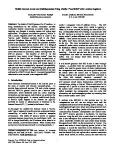
4.1 FEC-based CLVL construction
Overhead: FEC vs FEC+ARQ 35
In an FEC-based approach, we divide time into windows, where a window is a unit of encoding/decoding. We consider an erasure code such as Reed-Solomon, characterized by (n, k), where k is the number of packets arriving at the entry node during the window, and (n − k) represents the number of redundant packets added. Define the redundancy factor, r = (n − k)/n. The FEC problem reduces to determining a minimum redundancy factor, r, such that the target loss rate q is achieved. This problem is challenging because packet losses are unpredictable, and the algorithm must handle drastic changes in loss rate and correlated packet losses. Since the value of q may be one or two orders of magnitude smaller than p, we may not be able to afford to wait for feedback from the receiver about bursty losses in a window. Also, the time period of a burst may be comparable to the time for obtaining feedback from the receiver. So, rather than trying to predict the occurrence and magnitude of the next burst, we follow a conservative approach: We compute a statistical bound on the fraction of packets lost in a window due to bursts based on past history and set the redundancy factor to this bound. A burst induces unrecoverable losses in a window if the fraction of packets lost outnumber the redundancy factor. We calculate this bound such that the net losses caused by such bursts is less than q. More precisely, let f (p) denote the PDF of the loss rate p, where each value of p is measured over an encoding/decoding window. Then, for a given target loss rate q, we need to compute the smallest r such that: Z 1 pf (p)dp ≤ q. (1)
30
Overhead(%)
25
Pure FEC FEC+ARQ Pure ARQ
15
10
5 −2 10
−1
0
10
10
Target loss−rate(q) in %
Figure 3: Overhead (r): FEC+ARQ vs Pure FEC. In both cases b = 2M bps and the bottleneck link is 10M bps with a 9M bps self similar background traffic. Z
1
G(r) =
pf (p)dp.
(2)
r
The expected overhead, O, is simply r1 + G(r1 )(1 + r2 ). This yields the following optimization problem: Given a target loss rate q, determine the redundancy factors r1 and r2 that minimize the expected overhead, O = r1 + G(r1 ) × (1 + r2 ), subject to the target loss constraint: G(r1 ) × G(r2 ) ≤ q. Fortunately, for many loss distributions that occur in practice, the optimal solution for this problem is when r1 = 0. This solution implies that it is better not to use FEC in the first round, and use FEC only to protect retransmitted packets. Figure 3 compares the overhead characteristics for FEC+ARQ with pure-FEC and pure-ARQ based approaches. We make two observations. First, the overhead of the FEC+ARQ algorithm is much smaller than that of the pure-FEC algorithm. This is because, FEC+ARQ applies FEC only to the retransmitted packets, and the number of retransmitted packets is much smaller than the total number of packets. Second, when q ≥ p2avg , the FEC+ARQ algorithm reduces to the pure-ARQ algorithm, where r1 = r2 = 0. This is because in this case each lost packet is retransmitted only once; this is enough to achieve a target loss-rate ≤ p2avg . While FEC+ARQ is more efficient than pure-FEC, FEC+ARQ may require more time to recover. With the pure-FEC algorithm, the worst-case recovery time is W , where W is the length in time of the encoding/decoding window. In contrast, with the FEC+ARQ algorithm it may take RT T +W1 +W2 time to recover from losses, where RT T is the round-trip time between the entry and the exit node, and W1 and W2 are the sizes of the windows corresponding to rounds 1 and 2. For the simulation results shown in Figure 3, the values of RT T , W and W1 are set to 100ms each. The value of W2 depends on the number of retransmitted packets in a window which in turn is dependent on the loss-rate experienced by the window (worst-case: W2 = W1 , average-case: W2 = pavg × W1 ).
r
Computing r requires the knowledge of the distribution f (p). In practice, we estimate f (p) as follows. The OverQoS exit node for a bundle computes the loss rate p for each window and sends it back to the entry node. In turn, the entry node uses these samples to construct a histogram, and then uses this histogram to estimate f (p). Finally, the entry node computes r for the next window based on the estimated f (p). It turns out that our algorithm requires 2/q loss samples to accurately estimate r for a given value of q. Since we compute the histogram only using the last 2/q samples, we require the stationary property to hold only over relatively short time periods (of the order of minutes).
4.2 FEC+ARQ based CLVL construction While the FEC based solution is relatively easy to implement, it can incur a high overhead when the loss rate p is bursty (e.g., when f (p) is heavy-tailed). To reduce this overhead, we outline a hybrid FEC/ARQ approach that extends the previous FEC solution. Due to delay constraints for loss recovery, we restrict the number of retransmissions to at most one. We divide packets into windows and add a redundancy factor of r1 for each window in the first round. In the second round, if a window is non-recoverable, the entry node retransmits the lost packets with a redundancy factor r2 . We need to estimate the parameters, r1 and r2 . As in the previous case, let f (p) model the fraction of packets lost in a given window. The expected packet loss rate after two rounds is equal to G(r1 ) × G(r2 ) where:
ACM SIGCOMM Computer Communications Review
20
5. Examples of Using CLVLs In this section, we discuss three concrete examples of how CLVLs can be used by OverQoS to provide different types of services for end-to-end flows. The three examples we consider are: per-flow bandwidth differentiation, statisti-
14
Volume 33, Number 1: January 2003
Differentiating Flows in a bundle
Providing Guaranteed Bandwidth and Protection
2
1
Flow 1 Flow 2 Flow 3
0.9
1.6
0.8
1.4
0.7
Throughput(Mbps)
Throughput(Mbps)
1.8
1.2
1
0.8
0.6
0.5
0.4
0.6
0.3
0.4
0.2
0.2
0.1
0 250
300
350
0 250
400
Simulated Time(sec)
255
260
265
270
275
280
285
290
295
300
Simulated Time(sec)
Figure 4: Differential rate allocation for three classes within a bundle in the ratio 1 : 2 : 3.
Figure 5: Providing statistical bandwidth guarantees to QoS flows and protection to available-bandwidth ones.
cal bandwidth guarantees, and explicit-rate end-to-end congestion control algorithms. All these examples represent different ways in which the entry node distributes the CLVL available bandwidth, c, among the competing flows.
The remaining part of the available bandwidth can be distributed amongst the other available-bandwidth flows in the bundle. We illustrate the CLVL’s capability to provide this service model using a simple simulation. Consider a virtual link between two overlay nodes running a CLVL bundle for a target loss rate of q = 0.1% on top of an N -TCP pipe with N = 10. The virtual link traverses a bottleneck link of 10 Mbps and the cross-traffic comprises 50 long-lived TCP flows. By observing samples of c, the entry node determines cmin = 0.5 Mbps since P (c < 0.5Mbps) is negligible. The entry node of the bundle implements the DRR scheduling discipline. The bundle consists of three flows: (1) a QoS flow requiring a bandwidth guarantee of 0.5 Mbps, (2) a 3 Mbps CBR flow, and a (3) TCP flow. Flows 2 and 3 are available-bandwidth flows. Figure 5 plots the average bandwidth achieved by the three flows as a function of time. Flow 1 receives its guaranteed bandwidth with a loss-rate of only 0.02%. This is two orders of magnitude lower than the network loss rate of 2.44%. The TCP flow is protected against the aggressive 3 Mbps CBR (both flows have the same weight). Furthermore, the TCP flow in the bundle receives more bandwidth than a regular TCP since it experiences a lower end-to-end loss rate. Finally, when the TCP flow experiences a timeout, flow 2 takes advantage of this and uses the excess bandwidth. None of this requires any QoS machinery in the IP routers on the virtual link; all the required functionality is implemented exclusively at the overlay nodes.
5.1 Differential Rate Allocation A simple way of distributing c among the flows is to allocate the bandwidth in a proportionally fair manner. We can implement a Diffserv-like service by separating OverQoS flows into different classes and proportionally distributing c among the different classes. Figure 4 demonstrates this service for three different classes of traffic across a single CLVL. In this simulation, the bundle bandwidth is allocated in the ratio 1 : 2 : 3 using a DRR scheduling discipline [12]. Here, we assume a 10 Mbps link, and a 6 Mbps self similar background traffic. This ratio is strictly preserved even in the presence of a varying bundle bandwidth b (as estimated by N times the rate of a single TCP flow). While this example illustrates the differentiation across a pair of OverQoS nodes, we can easily extend the same model across the entire path in the overlay network.
5.2 Statistical Rate and Loss Assurances OverQoS can provide statistical rate and loss assurances that may be useful for streaming media delivery. If the net arrival rate at the entry node is less than c, then the entry node doesn’t have to drop any packets. Since c itself varies in time, it may not always be possible to avoid losses at the entry node. If the values taken by c can be modeled by a distribution, we can estimate a value cmin , such that P (c < cmin ) is small. cmin is a stable value as long as the underlying distribution of c is stationary. If cmin is non-zero, the entry node can admit flows with pre-specified bandwidth requirements such that the net bandwidth requirement is less than cmin . Since the net arrival rate of these flows is less than c with high probability, the CLVL abstraction can provide these flows with both statistical loss and bandwidth guarantees. We refer to these flows as QoS flows. Of course, we need an admission control module at the entry overlay node to allocate the bandwidth cmin amongst the QoS flows. Also, these flows can be admitted only over the period for which cmin is stable and fixed (typically of the order of minutes), and flows may renegotiate admission.
5.3 Explicit-rate Congestion Control An end-to-end path obtained by “stitching together” a sequence of CLVLs enables new end-to-end congestion control algorithms without IP router support. For simplicity, consider the case when all end-to-end flows traverse exactly one CLVL. Since the entry node knows c at any point in time, it can decide how to allocate c amongst the currently active flows in the bundle, ensuring that each ci allocated to flow i satisfies the P constraints that ci ≤ ai (the arrival rate of flow i) and i ci = c. Then, by providing this information to each flow as feedback analogous to XCP [9], cooperating end-hosts can send at rate ci , a rate that will not cause more
15
Volume 33, Number 1: January 2003
able [6]. In practice, we expect multiple OverQoS networks to coexist, an important question concerns the effect of multiple CLVLs sharing the same congested link. This question remains open, but our preliminary simulation results indicate that the N -TCP abstraction allows any number of CLVLs to seamlessly coexist and share the bandwidth of a congested link. In addition, our simulation results indicate that a bundle using N-TCP abstraction is also fair to the background TCP traffic.
than a small number of observable losses. One can extend this to flows that traverse multiple CLVL’s by setting the sender’s flow transmission rate to the minimum of the ci ’s returned along the reverse path.
6.
Discussion
We now discuss a few important aspects of the OverQoS design: The benefits of overlays, the power of controlled-loss and scalability issues. Why overlays? Overlays are easy to deploy compared to changes to the IP infrastructure. More importantly, they empower third-party entities other than traditional ISPs to offer enhanced communication services to clients. Similarly, OverQoS enables enterprises to build their own VPNs to provide communication services superior to the ones offered by traditional ISPs. The key to provide better services in OverQoS is the CLVL abstraction. CLVL allows applications to provide per-flow bandwidth differentiation, statistical rate assurance, and implement new congestion control algorithms without any QoS support in routers. There are two properties of CLVL that make it possible to implement these services in an overlay network: the ability to control the loss rate, and traffic aggregation. Controlled-loss: CLVLs achieve a predefined target loss rate, potentially at the expense of a reduction in the bundle’s throughput. This is different from other similar QoS mechanisms (e.g., Diffserv’s Assured Forwarding class) that provide a fixed-bandwidth abstraction but without any loss guarantees. There are two advantages of providing a controlled-loss abstraction. First, a controlled-loss abstraction gives more flexibility to the entry router in allocating a bundle’s resources among flows in a situation where no form of admission control is present. If the available bandwidth decreases, the entry node can choose to protect “important” flows by dropping the packets of the “less-important” ones. Second, since the loss seen by a bundle is in general much lower than the loss in the underlying network, we can more readily deploy new explicit-rate congestion control algorithms for flows within the bundle. Scalability: Scalability is an important concern in OverQoS: we look at the amount of state, the FEC overhead, and the number of OverQoS bundles below. Traditional solutions to provide fine-granularity services require to perform per-flow buffer management, scheduling, and eventually admission control. For very large bundles maintaining and managing the state for each flow in the bundle may not be feasible. To get around this problem we can use scalable techniques that were proposed at the IP layer to enhance Internet’s QoS, such as end-host based admission control [4], or dynamic packet state (DPS) [13]. There are two components of the FEC overhead: communication and processing. The communication overhead scales well with the bundle’s rate. In fact, the percentage of redundant traffic decreases as the rate of the bundle increases. This is because the number of packets sent during the same time window increases with the rate of the bundle. Our current untuned implementation can process 200 Mbps of FEC traffic on a 866 MHz Pentium III. Furthermore, in-order arrival of packets is well-suited to an implementation using pipelined, high-bandwidth FEC ASICs for Reed-Solomon codes. Such ASICs are commercially avail-
ACM SIGCOMM Computer Communications Review
References [1] D. Andersen, H. Balakrishnan, M. Kaashoek, and R. Morris. Resilient Overlay Networks. In Proc. 18th ACM SOSP, pages 131–145, Banff, Canada, Oct. 2001. [2] S. Blake, D. Black, M. Carlson, E. Davies, Z. Wang, and W. Weiss. An architecture for differentiated services, Oct. 1998. Internet Draft. [3] R. Braden, D. Clark, and S. Shenker. Integrated services in the Internet architecture: An overview, June 1994. Internet RFC 1633. [4] L. Breslau, E. W. Knightly, S. Shenker, I. Stoica, and H. Zhang. Endpoint admission control: Architectural issues and performance. In Proc. of ACM SIGCOMM’00, pages 57–69, Stockholm, Sweden, Sept. 2000. [5] Y. Chu, S. G. Rao, S. Seshan, and H. Zhang. Enabling conferencing applications on the Internet using an overlay multicast architecture. In Proc. of ACM SIGCOMM 2001, San Diego, CA, Aug. 2001. [6] Advanced Hardware Architectures. http://www.aha.com/. [7] A. Feldmann, A. C. Gilbert, and W. Willinger. Data networks as cascades: Investigating the multifractal nature of internet wan traffic. In Proc. of ACM SIGCOMM 1998, Vancouver, Canada, Aug. 1998. [8] J. Jannotti, D. K. Gifford, K. L. Johnson, M. F. Kaashoek, and J. O’Toole. Overcast: Reliable multicasting with an overlay network. In Proc. USENIX OSDI, San Diego, CA, Oct. 2000. [9] D. Katabi, M. Handley, and C. Rohrs. Internet congestion control for future high bandwidth-delay product environments. In Proc. of ACM SIGCOMM 2002, Pittsburg, PA, Aug. 2002. [10] S. Lin and D. Costello. Error control coding: Fundamentals and applications. In Prentice Hall, New York, NY, Feb. 1983. [11] T. S. E. Ng, D. Stephens, I. Stoica, and H. Zhang. Supporting best-effort traffic with fair service curve. In Proc. of GLOBECOM 1999, Rio de Janeiro, Brazil, Dec. 1999. [12] M. Shreedhar and G.Varghese. Efficient fair queueing using deficit round robin. In Proc. of ACM SIGCOMM 1995, Cambridge, MA, Aug. 1995. [13] I. Stoica. Stateless Core: A Scalable Approach for Quality of Service in the Internet. PhD thesis, Carnegie Mellon University, dec 1995. CMU-CS-00-176. [14] I. Stoica, H. Zhang, and T. S. E. Ng. A hierarchical fair service curve algorithm for link-sharing, real-time and priority service. In Proc. of ACM SIGCOMM 1997, Cannes, France, Aug. 1997.