Overview of Existing Safeguarding Techniques for Automatically Generated Code Ingo Stürmer
Daniela Weinberg
Mirko Conrad
Member of the ACM
Fraunhofer FIRST Computer Architecture and Software Technology
[email protected]
DaimlerChrysler AG Research and Technology REI/SM
[email protected]
[email protected]
ABSTRACT
Code generators are increasingly used in an industrial context to translate graphical models into executable code. Since the code is often deployed in safety-related environments, the quality of the code generators is of paramount importance. In this paper, we will present and discuss state-of-the-art techniques for safeguarding automatic code generation applied in model-based development.
Categories and Subject Descriptors
D.2 [Software Engineering]: Software/Program Verification, Testing and Debugging
General Terms
Design, Reliability, Human Factors, Standardization, Languages, Verification.
Keywords
Model-based development, automatic code generation, testing, modelling guidelines
1. INTRODUCTION
In the automotive sector, the way embedded software is developed has changed. Executable, graphical models are used at all stages of development – from specification to implementation as well as for testing (model-based development). Such models are designed with popular graphical modelling languages such as Matlab/Simulink and Matlab/Stateflow from The MathWorks. In the past, these models were implemented manually by programmers. Recent approaches allow the automatic generation of efficient controller code directly from the software model via socalled code generators (model-based code generation). Code generators, such as TargetLink [4] or the Real-Time Workshop [5], are examples of software tools upon which software designers rely since the code generated is often deployed in safety-related environments (e.g. brake systems). Furthermore, the adoption of reliable tools such as code generators is a crucial factor for competitive embedded software development. However, at present, code generators are not as mature as C or ADA compilers which have been proven reliable in use; thus, their output must be checked with almost the same, expensive effort as is needed for © ACM, (2005) This is the author’s version of the work. It is posted here by permission of the ACM for your personal use. Not for redistribution. The definitive version was published in ACM 1-59593128-7/05/0005. http://doi.acm.org/10.1145/1083190.1083192
manually written code. For that reason, code generators must be safeguarded as part of the model-based development tool-chain to such an extent that errors possibly incorporated by inappropriate modelling or by the code generator itself can be detected and avoided as far as possible. In this paper, we will give an overview of existing safeguarding techniques for automatically generated code. The term “safeguarding” refers to techniques and procedures which are applied in practice to increase confidence in the generated code as well as to those techniques which ensure that the code generator works as expected. In that context we will discuss which one of the respective development artefacts (i.e. model, generated code) and tools (code generator, compiler, etc.) can be safeguarded. For that purpose, we will first observe safeguarding techniques for the code generator itself. We will then discuss certain requirements that the model should comply with since models are the central part of the whole model-based development process. These models not only serve as a basis for software design and implementation but also for testing. Furthermore, they are designed by humans and are the input for the code generator. It is worthwhile to note that the quality of the code generated is closely connected with the quality of the model. Finally, we will focus on the code generated and discuss how it can be safeguarded during the development process.
2. MODEL-BASED CODE GENERATION
In model-based development, the seamless use of executable models is characteristic for function and control system design and the following implementation phase. This means that models are used to represent the development of the system from the preliminary to the detailed design. At the beginning of this model evolution there is usually a so-called physical model, which is derived from the functional specification of the software component to be realised (ref. Figure 1). The physical model contains the control function to be developed and describes the behaviour of the control function related to a given (continuous) input signal as well as internal or external events or states. The purpose of the physical model is to depict the algorithms to be developed “in their purest form” without already having to pay attention to realization details. The description of the algorithms thus takes place through the use of floating-point arithmetic. Since this model can already be executed in a simulation environment on the development computer (host PC), it is also called an executable specification. For reasons of efficiency and because of the fact that the real input and output in the physical model is abstracted where necessary, the physical model cannot serve directly as a basis for deriving production code for the target processor. It is therefore revised from a realization point of view (for example function parts are distributed to different tasks) and enhanced with the necessary
implementation details. In order to do this, the floating-point arithmetic contained in the physical model is adjusted to the arithmetic of the target processor (for example 16-bit fixed-point). This means in particular, that only fixed-point data types are used (e.g. int16), which are provided with scaling information in order to keep imprecision in the presentation of fixed-point numbers as low as possible. The result of this adaptation is an implementation model which contains all the information necessary for code generation and makes the creation of efficient C-code possible. The principle of automatic code generation presented in Figure 1 also shows the tools involved in the model-to-code translation process. Depending on the purpose, the code is generated on a host PC (development environment) whereas a classical compiler/linker combination is used for the translation of the generated code. For an embedded processor (experimental hardware or electronic control unit (ECU) ) a so-called cross-compiler is required with a linker and a loader which allows to bring the machine code onto the embedded device. The sources of errors, which can be identified within this development tool-chain, are (1) design errors which are caused due to inappropriate design of the (physical) model with respect to the functional requirements or due to misunderstandings regarding the semantics of the modelling language; (2) arithmetic errors due to imprecise representation of the control function’s arithmetic within the implementation model or due to improper floatingpoint to fixed-point conversion (e.g. quantization errors); (3) tool errors incorporated by a tool within the tool-chain that contains implementation bugs or that has not been set up correctly (e.g. code generator configuration); (4) hardware errors of the development or target environment itself; (5) run-time errors caused on the target hardware due to e.g. resource demand mismatches, scheduling etc.; and (6) interface errors between the generated control algorithm, legacy code (e.g. custom code) or wrapper software (driver, operating system etc.). Physical Model (floating-point)
Compiler (Linker) Code generator
Implementation Model (fixed-point)
Host PC
C Code
Target Cross-compiler (Linker / Loader)
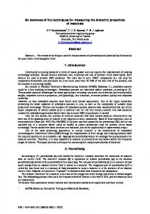
Figure 1: Principle of Automatic Code Generation In the following, we will present safeguarding techniques which are applied in practice in order to reveal possible errors within the code generation tool-chain.
3. SAFEGUARDING THE CODE GENERATOR
Usually, the tools that are most likely to be correct are those which have been well designed and written, and which, above all, have been developed with correctness in mind [6]. In the context of model-based development, those techniques and procedures
which are applied in practice to increase confidence in the code are the most relevant ones. They can generally be divided into constructive procedures (e.g. adoption of standards and guidelines) and analytical procedures (e.g. verification and testing). In the following, we will provide an overview of common constructive and analytical procedures.
3.1 Adoption of Standards and Guidelines
Constructive procedures guarantee that the tool has been developed according to a systematic development process. Such a process is often defined in accepted standards or guidelines. This also includes the certification, or, more precisely, the qualification of the code generator. For that purpose, the tool supplier should develop his tool within an established Quality Management System (QMS), which should preferably be externally certified to a recognised standard (e.g. ISO 9001 with the TickIT Guidelines).
3.1.1 SPiCE and CMM
Over the years, a large number of software quality standards have emerged. In the early 1990s, a working group from ISO/IEC was set up to define a common standard based on existing international and corporate standards. In 1995, a new standard was published. This standard was mainly influenced by CMM (Capability and Maturity Model), Bootstrap and the ISO 9000 series. The first version of the standard was first published in 1995 and underwent trials as part of the European SPiCE (Software Process Improvement and Capability determination) project. CMM, ISO 9001 and ISO/IEC 15504 are process-oriented development standards that provide a framework for managing the increasing complexity in software development. The SPICE standard is also highly suitable for developing a code generator cf. [3], [7], [13].
3.1.2 MISRA C
The most important technical standard for any code generator is the standard for its output language [7]. Most code generators produce C code, which is standardised internationally by ISO/IEC 9899 (identical to ANSI X3.159). However, there are several supplementary standards and publications. In this paper we will focus on the MISRA-C Standard, which has gained much acceptance in the automotive industry so far. Since 1998, a commonly accepted standard called "Guidelines for the Use of the C Language in Vehicle-Based Software" (MISRA-C:1998) has existed, which was developed by the British Motor Industry Software Reliability Association (MISRA) and defines 127 coding rules. The rules aim at avoiding common (human) programming errors. For this reason, complying with all the rules does not necessarily have a positive impact on automatically generated code. However, there is actually no code generator which is capable to generate efficient code which also conforms to the MISRA rules (examples for acceptable rule violations due to efficiency problems are presented in [7]). It is worth it to note that that the MISRA consortium has not faced this dilemma within the newly revised MISRA-C:2004 standard.
3.2 Tool Certification (Qualification)
Certification can be defined as a third party assessment made by an official and independent organization. It is a way to protect a tool supplier as well as the customer: the customer can be sure that the product satisfies commonly admitted characteristics. The supplier gets an independent approval that techniques, applied for developing and verifying the product, are in compliance with the safety requirements for the specific criticality level. Certified code generators would permit to certify safety-critical software on
the model level, which promises to be less time-consuming, cheaper, and more reliable then the current practice to inspect the source code and/or generated machine code. There are two widely accepted software (system) certification standards: the avionics process standard DO-178B and the international safety standard IEC 61508. Both are discussed with respect to code generator certification in the following:
3.2.1 DO-178B
Avionic standards such as DO-178B encourage the qualification of code generation tools. Qualifiable code generators, such as SCADE, which endorse a certification of the application software, do exist. However, they only make it possible to reduce the amount of some of the verification activities but do not allow them all to be omitted completely. In addition, their source language is not as popular as Simulink / Stateflow and they perform only a limited amount of optimisations. The qualification of a development tool can be treated similarly to the certification of the application software itself. Thus, qualifying a development tool such as a code generator does not mean proving its correctness. Instead, it is important to gain sufficient confidence in its correctness [6].
3.2.2 IEC 61508
IEC 61508 is an international safety standard which can be adopted for certifying safety-related (software-based) system parts. Certification is not explicitly formulated within the scope of IEC 61508. However, in the terms of IEC 61508, software must be assessed by an independent certification body with respect to the aspired Safety Integrity Level (SIL) of the (software-based) system. In the case of IEC 61508 the TÜV (Germany) and Factory Mutual (US) are generally accepted as suitable certification bodies. In the context of IEC 61508, to date, only compilers (translators) are regularly subjects to tool certification procedures. Compiler (or translator) assessment is possible in two different ways: (1) the compilers or translators are certified against their respective language or process standards (2) Compilers or translators are assessed by their increased confidence from use (i.e. correct performance demonstrated in many projects). Following the certification practice of the TÜV it is also possible to certify a code generator by establishing its “Fitness for Purpose”. This procedure proposes that an assessment should be carried out in order to ensure that the tool is fit for its intended purpose (However, in the IEC 61508 guidelines it is left open how such an assessment is to be performed). ASCET-SD, developed by ETAS, is the first code generator for automotive embedded control systems that is certified as being fit for its purpose for SIL 3 according to IEC 61508 [13]. In order to gain this certificate the TÜV inspectors analyzed the ETAS tool-chain intensively so to understand the purpose of its use and the tool’s development process. Based on this knowledge, the inspectors created a test plan according to the IEC 61508 SIL 3. This test plan should access the “Fitness for Purpose” of the code generator and includes, for instance, formal characteristics of the documentation, software requirements specification, the test as part of design, development and integration, verification and validation (V&V). Following that test plan the tool developer could show, as an example, “the existence of conclusive evidence for correct code generation” [13].
3.3 Testing and Verification
Analytical procedures are methods and techniques which assure that (design) errors within the tool have been detected or
avoided as far as possible with methods such as testing or formal verification. Such analytical procedures are also often termed verification and validation (V&V) methods.
3.3.1 Code Generator Testing
Code generators which translate a high-level graphical language into efficient code constitute a new kind of development tool and, as a result, systematic testing approaches are largely unexplored or unpublished. However, the few published testing procedures for code generators used in practice can be divided up into four categories, which are often adopted consecutively or in combination with each other cf. [3], [7], [11]: • Test of Core Capability: with the testing of the core capabilities, individual Simulink and Stateflow blocks (basic blocks) as well as code patterns which are applied during code generation, are tested rigorously against expected values. These blocks (and patterns) are varied with respect to data types and scaling information and are executed on different target processors. Consequently, it is quite common to have a few hundred thousand test cases. The execution and result evaluation is largely automated. • Test of Core Capability Combinations: combinations of individual blocks and frequently used modelling patterns are tested against expected values. Here, the main focus is often placed on the optimisations performed by the code generator. The determination of expected values as well as test result evaluation is performed manually. Large-Scale Usage of Core Functionality: large customer • models are used to check the tools for robustness and correctness. The test results are analyzed in detail by experts. • Test of Code Generator Configuration: a (semiautomatic) system test checks the installation, configuration and operation of the code generator on different PC configurations and together with different software versions of the tools involved in the tool-chain (e.g. compilers). A reliable and accepted way to increase confidence in the correct functioning of a translation tool such as a code generator is to validate the code generator by means of a test suite, which is common practice for compiler validation [11]. For this reason, a generic Autocode Validation Suite (AVS) is now under construction, which is capable of thoroughly validating a specific translation function (e.g. optimisations) applied by a code generator. The theoretical foundations of the test suite have been presented in [1] which also defines a general procedure for testing code generators systematically.
3.3.2 Code Generator Verification
A very strong approach for demonstrating the conformance between implementation and design is to formally prove that the implementation has the same semantics as the design. Several compiler proofs have now been published [9]. However, under realistic conditions, the industrial benefit of the code generator verification approach could not yet be shown: There is currently no formally proven compiler in use which has reached industrial maturity. Nobody has succeeded in producing a correct compiler for a realistic programming language for two main reasons [10]: first, the range and precision limitations on computers were ignored; second, the formal methods chosen to describe the source and the target language and the intermediate languages in the compiler made the treatment of realistic programming languages too difficult. As a consequence, attention was restricted to rela-
tively simple programming languages, disregarding the complexities and pitfalls of realistic languages.
intended, but will find constructs which might be erroneous or non-portable, as well as constructs that do not behave as expected.
4. SAFEGUARDING THE MODEL AND THE GENERATED CODE
4.5 (Model-based) Testing
So far, we have taken a closer look at the code generator itself. Now we will focus on the input provided to the code generator and the output it produces.
4.1 Modelling Guidelines
The quality of the (implementation) model substantially determines the quality (correctness, efficiency etc.) of the generated code. Therefore, guidelines and patterns for model design exist, such as those published by the MathWorks Automotive Advisory Board (MAAB Guidelines). Following the modelling conventions stated in such guidelines allows for the translation of the model into safe and efficient code. In order to ensure the efficient management and publishing of such guidelines and pattern collections, specific tool support is necessary, such as presented in [8]. The latter collection describes typical problems and suggests base-patterns that should be used and reused during the development of functions in order to avoid troubleshooting during or after code-generation. However, the adoption of guidelines and patterns for modelling has certain advantages: (1) increase of comprehensibility (readability), (2) maintainability, (3) reusability and extensibility, and (4) ease of testing.
4.2 Autocode Aspects
In order to assure that the quality of manually-created code is acceptable, it is common to verify and validate the code by using techniques such as reviewing, testing, and static analysis. However, if the code is generated automatically by means of a code generator, any errors will tend to be systematic, because the tool should behave identically for the same model and code generator configuration. [2] compares the V-model for plain, manually generated code using models and automatically generated code and points out the advantage of model-based code generation. However, in the following we will present safeguarding techniques for automatically generated code.
4.3 Autocode Review
Reviewing manual code is a widely accepted practice used to find errors in the code. In order to do this, the code needs to be well-structured and documented. In contrast to manual code, the code generated automatically will have a low density of faults, if the code generator used works properly. Autocode peer review can be quite effective (even though it is inefficient) since inappropriate modelling and improper variable scaling, for instance, is easier to detect in the code than in the model.
When testing manual code, the main focus is on testing the functionality of the code and ensuring that the code is correct. Testing, thus, does not verify the code against its design. In the case of automatic code generation, however, the model is tested against its requirements and the code can be verified against the executable model by means of dynamic testing. For this purpose, that both the model and the code are executable can be exploited. Both executables are stimulated with the same inputs (cf. Figure 2). Afterwards, the two outputs will be compared with respect to certain acceptance criteria. This comparison yields some technical problems that must be considered. Due to quantization errors, the outputs of the model, for instance, and the output of the generated code are usually not identical. As a consequence, sophisticated signal comparison methods have to be applied. The question what constitutes appropriate test stimuli for model and code testing is fundamental. The use of structural testing criteria on model level (model coverage) and code level (code coverage) for test stimuli determination is meanwhile widespread in practice. Model coverage supplements the known benefits of code coverage, namely controlling the test depth and detecting coverage holes in given test suites. Furthermore, test stimuli generation for model and code coverage can be automated by the use of test vector generators such as Reactis1 for model coverage or the Evolutionary Test Tool [14] for code coverage. One of the great advantages of model-based development is the opportunity to simulate the model and the generated code at different stages of the development process. Here, different ways of simulation (cf. Figure 2) support the safeguarding of the model and the generated code: Model-in-the-Loop (MiL): MiL simulation captures the • specified behaviour of the model that is to be implemented in C code later on. This simulation is executed on the host PC. The simulation results are used as a reference (expected values) for the following software verification steps. The aim of MiL is to check the validity of the model with respect to the functional requirements within the development environment. Additionally possible simulation pathways within the model can be measured with model coverage criteria (e.g. decision coverage or MC/DC coverage). •
Software-in-the-Loop (SiL): The implementation model that was used during MiL is now compiled and executed on the host PC with the same stimuli used for MiL. The execution results should be comparable to the results obtained during MiL. Results can differ, however, due to different handling of numerical instabilities or exceptional handling of the MATLAB simulation environment and the code executed. The aim of SiL is to analyze fixed-point scaling effects of the generated code, to detect possible arithmetical problems (e.g. over-/underflow), and to measure code coverage.
•
Processor-in-the-Loop (PiL): The generated code is (cross-) compiled using the project’s target compiler. Afterwards, the code is executed on an experimental hardware, which contains the same processor as the target system (such
4.4 Static Analysis
There may be situations in which static analysis tools can help in the process of reviewing the code. Advanced static analysis tools, which are available for languages such as C, can extract from code the essence of what it actually does. This may be easier to be compared with the input notation than the actual generated code itself. Such analysis tools check the syntactic correctness and, to varying degrees, the semantic correctness of programming language source code. They add a greater degree of rigour to the kind of checks performed by a compiler. These tools will not check whether the code has the functionality the programmer
1
http://www.reactive-systems.com
as an evaluation board) but contains additional resources for storing and exchanging test data and test results. The aim of PiL is to verify the code behaviour on the target processor and to measure code efficiency (profiling, memory usage, etc.). •
Hardware-in-the-Loop (HiL): Finally, during Hardware-inthe-loop simulation, the software embedded into the target ECU is executed. For that purpose, the ECU is connected to a real-time simulation system simulating the plant. Thus, the aim of HiL is to check the software on the ECU with its electrical interfaces. Test model
Test output (Model)
modes. These simulation modes are especially relevant in order to verify the model at an early stage in the development process. As we can see from the variety of techniques available, there is not just one way to make the automatically generated code more reliable. Moreover, it is a matter of how to combine available techniques in order to increase confidence in automatic code generation.
Acknowledgement
The work described was partially performed as part of the IMMOS project funded by the German Federal Ministry of Education and Research (project ref. 01ISC31D). http://www.immosproject.de.
6. REFERENCES
[1] Stürmer, I. and Conrad, M. Test Suite Design for Code Generation Tools. 18th Int. IEEE Conf. on Automated Software Engineering, pp. 286-290, 2003.
MiL
test stimuli
Code generator Test output (Host PC) ≈
SiL
Code
Test output (Experimental HW)
Compare results
PiL Test output (ECU)
HiL
Figure 2: Process for Testing Automatically Generated Code
5. CONCLUSIONS
In this paper we have taken a closer look at safeguarding techniques for automatically generated code. A survey of possible safeguarding techniques for automatic code generation is presented in the appendix. As we have seen, the code generator itself should have been developed with correctness in mind and within an established quality management system. Furthermore, the code generator should be validated by an Autocode Validation Suite, which is capable of verifying the code generator’s correct implementation [12]. But how can a code generator work correctly if the input model it is given is not set up well? So, the second important issue is the input model for the code generator. Since there is no published standard for graphical modelling languages available, it is recommended that the developers of such models have a cross-discipline skill set. It would certainly be an advantage if model developers used a commonly accepted and thoroughly tested set of base-(sub)models. This would make models from different developers more alike in appearance and therefore the models would be easier to read and understand for others. Overall, a common set of patterns and guidelines used widely in practice may lead to a national or international standard for such graphical models in the future. The third issue we considered was the generated code. We described practical ways of gaining confidence in the code. These techniques range from manually reviewing the code and having tools analyze the code up to different simulation
[2] Burnard, A. Verifying and Validating Automatically Generated Code, Int. Automotive Conference (IAC), pp. 71-78, 2004. [3] Beine, M., Otterbach, R. and Jungmann, M. Development of Safety-Critical Software Using Automatic Code Generation, Society of Automotive Engineers (SAE), 2004-01-0708, 2004 [4] dSPACE. TargetLink 2.0: Production Code Generator. http://www.dspace.com, 2004. [5] The MathWorks. RealTimeWorkshop/Embedded Coder, http://www.mathworks.com, 2004. [6] Edwards, P.D. The Use of Automatic Code Generation Tools in the Development of Safety-Related Embedded Systems. Vehicle Electronic Systems, European Conference and Exhibition, 9.-10. June, 1999. [7] Thomsen, T. Integration of International Standards for Production Code Generation, Society of Automotive Engineers, Doc.-No.: 2003-01-0855, 2003. [8] Conrad, M., Dörr, H., Fey, I., Pohlheim, H., Stürmer, I. Guidelines und Reviews in der Modell-basierten Entwicklung von Steuergeräte-Software (in German), 2. Tagung Simulation und Test in der Funktions- und Softwareentwicklung für die Automobilelektronik, March 14.-15, 2005. [9] Dave, M. A. Compiler Verification: a bibliography, ACM SIGSOFT Software Engineering Notes, Vol. 28 (6), 2003. [10] Goos, G. and Zimmermann, W. Verifying Compilers and ASMs, Abstract State Maschines, LNCS, 1912:177-202, Springer, 2000. [11] Tonndorf, M. Ada Conformity Assessments: A model for Other Programming languages? ACM SIGAda Ada Letters, Vol. XIX (3), pp. 89-99, 1999. [12] Stürmer, I., Conrad, M. Code Generator Testing in Practise, 2nd Workshop Automotive Software Engineering, 2004. [13] Junker, F., Glöe, G. Guaranteed Product Safety According to the IEC 61508 Standard, RealTime, Vol. 1, pp. 28-29, 2003. [14] Wegener, J., Stahmer H. and Baresel, A. Evolutionary Test Environment for Automatic Structural Testing. Special Issue of Information and Software Technology, Vol. 43, pp. 851-854, 2001.
Appendix: Safeguarding Techniques for Automatically Generated Code Aspect
Safeguarding technique
Physical model (PM), Functional MiL simulation / testing implementation model (IM)
Code Generator
Possible Aims • Verify that the model (PM, IM) reflects its functional requirements specification • Check validity of the model within the development environment without resource limitations of target environment • Verify floating-point to fixed-point conversion (PM IM)
Structural MiL testing (model coverage)
• Explore possible simulation pathways within the model by determining test cases on the basis of the model structure
Adoption of modelling guidelines
• Rely on experiences and expert knowledge • Use well-known patterns for safe and efficient code generation • Avoid error-prone modelling constructs
Model review
• Reveal design errors at an early development stage • Ensure that modelling guidelines have been applied
Adoption of development standards • Ensure that the code generator has been developed following a sysand guidelines tematic development process / quality management system Tool certification (qualification)
• Independent approval which guarantees that techniques, applied for developing and verifying the tool, are in compliance with the requirements of a certification standard
Testing (Autocode Validation Suite)
• Ensure that the code generator has been tested rigorously • Validate that specific translation functions (e.g. optimisations) behave as expected • Replacement of tool certification by using a certified Autocode Validation Suite
Formal proof
• Show by means of mathematical proofs that each code generation (rule) preserves the model’s semantics
Restriction to a safe subset of the code • Increased confidence by using only ' well known'features generator functionality • Restriction of V&V activities to only those features which are relevant Generated Code
Functional SiL simulation / testing
• Analyze fixed-point scaling effects • Detect arithmetical errors • Rapid prototyping
Functional PiL simulation / testing
• Check validity of code behaviour taking arithmetical constraints and resource limitations of the target processor into account • Analyze fixed-point scaling effects on target processor • Measure code efficiency
Functional HiL simulation / testing • Check behaviour of code within the target environment (ECU) with its HiL-Simulation / Testing electrical interfaces Structural MiL / SiL / PiL testing (code coverage)
• Determine test cases on the basis of the code structure • Explore possible execution pathways within the code by determining test cases on the basis of the software structure
Code review
• Find errors caused by inappropriate use of the code generator • Reveal implementation errors caused by integration of custom code parts • Detect errors within the implementation model (which are hard to find in the model) • Identify inefficient code parts
Static analysis
• Check that code conforms to coding guidelines (ANSI C, MISRA C) • Detect dead code, etc.