Overview of the Development for a Suite of Low-Thrust Trajectory Analysis Tools Larry D. Kos*, Tara Polsgrovet, Randall C. Hopkins’, Dan Thomas§ NASA Marshall Space Flight Center, Mail Code VPl I , Huntsville, AL 35812
and Jon A. Sims** Jet Propulsion Laboratory, Pasadena, CA 91109
A NASA intercenter team has developed a suite of low-thrust trajectory analysis tools to make a significant improvement in three major facets of low-thrust trajectory and mission analysis. These are: 1) ease of use, 2) ability to more robustly converge to solutions, and 3) higher fidelity modeling and accuracy of results. Due mostly to the short duration of the development, the team concluded that a suite of tools was preferred over having one integrated tool. This tool-suite, their characteristics, and their applicability will be described. Trajectory analysts can read this paper and determine which tool is most appropriate for their problem.
I. Introduction N this paper we review the development and completion of a suite of new low-thrust (LT) interplanetary trajectory tools that will significantly increase the analytical capability of the LT community. This suite of tools is available per the requirements set forth by each lead developer, as described in section VI below. As future missions are likely to continue the use of highly efficient electric propulsion, and may increasingly use low thrust, analytical capabilities can now grow to support this need. Original “marching orders” dictated that this capability be a tool that would be as widely available as possible, be as inexpensive as possible to all potential users, be user-friendly, and facilitate generation of consistent results by different analysts -- without extensive tutoring. In the past, NASA Headquarters has received mission analyses on the same mission run by different analysts at different centers, sometimes using the same analysis tool and sometimes using different tools, that were different to the extent that the feasibility of the mission in question was not settled by the results of those tools. Part of the impetus behind this LT tool development activity was to prevent this scenario from occurring in the future. Of course, this occurrence was not common, since this tended to occur on missions that pushed both the analysis tool and spacecraftperformance limit (on paper, in the analysis). The end result is a suite of tools, instead of a single tool, that meets these “desirements” to the extent possible. Each tool’s characteristics, applicability and availability are discussed in the following sections. The tools’ similarities will be compared, allowing an analyst to choose a tool for a particular analysis for other reasons (to be discussed in section III). Each tool’s unique strength or “niche” applicability are also discussed, i.e. when unique problems can be assessed using only one or two tools in the suite.
I
11. Purpose and Goals The purpose of this low-thrust trajectory tool (LTTT) activity was to produce a tool or suite of tools that would allow the mission design community to do interplanetary LT trajectory analyses that: 1) would be consistent * Aerospace Engineer, Advanced Concepts Office, NASNMSFC Mail Code VP11, Senior Member AIAA.
Aerospace Engineer, Advanced Concepts Office, NASAMSFC Mail Code VP11. Aerospace Engineer, Advanced Concepts Office, NASAJMSFC Mail Code VP11. § Aerospace Engineer, Advanced Concepts Office, NASNMSFC Mail Code VP11. ** Senior Member of Engineering Staff, Guidance, Navigation, and Control Section, 4800 Oak Grove Drive, Mail Stop 301-140L, Senior Member AIM. 1 American Institute of Aeronautics and Astronautics
-
(between various NASA centers and between various analysts), 2) could be quick turn-around at times when needed (e.g. in hours or days), and 3) would have analysis fidelity levels that could be partially electab able", determined by time allowed. Goals for the actual tools themselves included that they be easier to use than previous tools, they provide better and/or faster results than previous tools -- both if possible, and provide for more accurate modeling of the force model and environment models than previous tools.
111. The Suite of Tools There are a number of tools that preceded this work, and a number of tools came out of this effort as well. Table 1 shows the list of the five tools in our new suite of tools, along with a short list of some of the predecessors. The new tools’ abbreviated names are shown in bold to distinguish them from the previous tools.
SEPTOP NEWSEP Sail
(VARITOP-based) Solar Electric Propulsion Trajectory Optimization Program New (VARITOP-based) Solar Electric Propulsion Trajectory Optimization Program VARITOP customized for Solar Sails
A. Brief Tool Overview Below is a very short synopsis of each tool. For more detailed information on each tool, check the references for a concurrent A I M paper in this conference (2006 Astrodynamics Specialist Conference) or the tool User’s Guide or both.
I. M A L T O ~ - ~ MALTO is the only medium fidelity tool developed during this software development effort. It is intended to be the starting point for nearly all low-thrust trajectory and mission preliminary design studies. It is designed to run faster and with fewer inputs than a high fidelity tool. MALTO is the tool of choice for running trade studies with up to three independent variables (i.e. a three-dimensional trade-space). MALTO is also the only tool in the suite that is used to perform solar sail analyses. MALTO was in the spotlight earlier this year when it was the main tool used by JPL win the lStESA Advanced Concepts Team (ACT) Global Trajectory Optimisation Competition. 2. ~ y s t i c ~ , ’ Mystic is one of three high fidelity tools with its niche being trajectory optimization of the entire trajectory or mission. Mystic is most applicable towards determining an overall optimum trajectory (e.g. minimum fuel or minimum trip time for a given propellant load) due to its unique optimizer called “StaticlDynamic Control” (SDC). This SDC optimizer is a patented algorithm, developed by Dr. Greg Whiffen. The algorithm, for example, can find and utilize gravity assist maneuvers when they are beneficial to the problem solution without explicit commands or inputs. 3. Copernicus6-8 Copernicus is another high fidelity tool that utilizes segments to piece together a desired mission trajectory. The available options for segments, comprising a dozen different types, are: continuous thrust, coast, starting or ending impulses, etc., for example. A feature of designing trajectories with a set of predefined segments allows a mission to be modeled with multiple propulsion systems, including high thrust, low thrust, and variable thrust, and also allows the user to enforce such constraints as crew wakelsleep cycles that apply to human missions. A real-time graphical user interface (GUI) displaying the current trajectory analysis iteration is also a prominent feature of Copernicus. 4. 0 ~ 1 s 9 - l ~ OTIS version 4.0 is the new re-formulated version of OTIS v3.2. It is now fully intended to be used as a high fidelity heliocentric analysis tool as well as its more commonly known use for Earth-to-orbit analyses. It is easier to use with the simplified input scheme and utilizes new mathematics (using collocation and pseudo-spectral methods as selectable options). OTIS carries forward from older versions the capability to model propulsion systems at a higher level of fidelity, thus providing for sizing at the subsystem and component level.
2 American Institute of Aeronautics and Astronautics
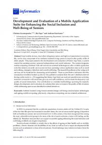
5. SNAP'^ SNAP is the only tool in the suite that focuses primarily on planet-centered analyses. It is a high fidelity propagator which accepts various types of pointing control laws to determine fuel, time, and path requirements. Simple heliocentric trajectory analyses can also be done with SNAP. B. Tool Capabilities Figure 1 provides a “fust glance” view of the basic overlap of capabilities among the various tools. The figure shows that while the tools each have some niche for their application, there is also some amount of common analysis capability resident in each. Reference 13 is also a much more in-depth look at the specific capabilities of each tool.
[ [
] Mystic ] OTIS 4.0
I-]
Copernicus [-] MALTO \ --d ’ VARITOP CHEBYTOP [ ] SNAP, other
’
Figure 1. Conceptualized overlap in capability of the five tools in the low-thrust trajectory tool suite. This capability overlap also shows two of the earlier tools in use -- VARITOP and CHEBYTOP. VARITOP was considered state-of the-art for medium fidelity analysis, and CHEBYTOP was considered state-of the-art for quickturnaround low fidelity analysis. Their capability outline is shown with a dashed line, as opposed to the solid line used for the five tools in the new LTTT suite. Other tools also in use, but not shown in the overlap figure due to their derivation from and similarity to VARITOP, include SEPTOP, NEWSEP, and Sail. C. Tool Selection Process Beyond the convention of always using MALTO, the medium fidelity tool, to begin analyses, the following is a process the reader can use when deciding which tool to run. The first step is to determine which tool has the greatest applicability for their problem. The synopses above, along with the comparison table, shown in Fig. 2, is a starting point for this process. Other major factors that will determine tool selection is the platform it runs on , the additional software licenses needed by the tool, and ITAR restrictions. Other characteristics of interest, and lesser ones that may affect the tool selection is the main or most common1 used mathematical algorithm used in the tool, and the main or most commonly used optimizer (e.g. SNOPT’J is an available option in three of the five tools). Figure 2 shows a brief summary of these criteria. Note that some of the tools have high thrust (HT) analysis capability as well. Projected turn-around time for a problem solution will also determine which tool is selected. The faster the answer is needed, the more likely it will be for an analyst to select the medium or even the low-fidelity tool. Note that while the low fidelity tool is available, it is not considered part of the newly developed suite of five tools.
3 American Institute of Aeronautics and Astronautics
MALTOv4.4
I
JPL
M
y
JSClUT
s
e
GRC
Copernicus
I
static &
Algorithm(s) Main Optimizer
Yes
StaticlDynamic Control Yes
MATLAB.
MATLAB'
SNOPT
GUI Source Code
100% Fortran
SNOPV MATLAB* Is it ITAR?
Yes'. v7.1-1.5 Yes*
cost Application (PrlmaV)
I
I
Yess Free
I
Low-thrust Interplanetary, some high thrust
Impulsive & Finite-bum AV segments
Implicit Integration
Numerical Integration
SNOPT
SNOPT
nla
Yes
No
WtnteracterlOpenGL
100% Fortran No Yes* Yes (I) I Low-thrust Interplanetary, N-body
GRC
SNAP v2.3
Yes Excelerator/Mac
100% Fortran
100% Fortran
Yes'. v6.2 No No Free
Yes'. v6.2 No Yes Free
100% Fortran No No No Free
Low-thrust Interplanetary, N-body, & E T 0
Low-thrust Planetocentric, N-body, some helio.
Low-thrust Interplanetary, N-body. & HT
I
IV.
Beta Testing Thirty-two reference missions were selected for beta testing. The list of these missions can be found in the Appendix. A. Reference Mission Case 1 Comparison Reference Mission 1 , a very simple case, is selected from the beta testing to illustrate the overlap between the tools. Figure 3 shows a brief summary for the fxst reference mission, an Earth-to-Mars flyby using fixed: departure velocity (1.66 k d s ) , flight time, initial mass, departure date, and in most cases specific impulse (Isp). Dependent parameters, below the gray separator bar, which match very closely are the final mass at Mars closest approach (all less than 1% different) and the thruster on-time (all within 1%). The inaccuracies in CHEBYTOP that do appear are mainly a result of the mapping of the variable Isp solution to an approximate constant Isp solution. Note that, to the extent of the fidelity (i.e. accuracy) of the tools, the dependent variable of final mass (at Mars periapsis) agrees well between tools for this problem. Additional selective documentation of the beta testing for the LTTT suiteif tools is also in Reference 13. -
Parameter
0.581
Heliocentric Flight Time Initial Mass in Earth Orbit
days
MALT0 Copernicus OTIS 5120103 512012003 5120103 2.6 2.6 2.6 0.581 0.581 , 0.581 200 200 200 585 585 585
1
3337 3337 Specific Impulse 554.4 554.3 Mass at Mars Periapsis kg 554.4 559.2 Heliocentric Thrusting Time days 125.8 , 125.6 3337 125.0 3337 n/a Figure 3. Simple reference mission case for comparing tools in LTTT suite.
3337 554.3 125.8
Mystic 5120103 2.6 0.581 200 585 3337 554.5 125.0
B. Beta Testing Summary and Long-term Beta Testing Goals More than sixty percent of the beta test cases have been completed. NASA plans to publish an extensive technical memorandum (TM) containing all reference mission run with all applicable tools of the LTTT suite as a follow-up product to the initial conference papers and presentations. 4 American Institute of Aeronautics and Astronautics
V.
Web Site
The web site, located at http://www.inspacepropulsion.corn/LTTT/, is intended to provide a central location for low-thrust trajectory and mission analyses on-going within NASA. Various types of information and resources will continue to be added to the site as they are organized. Much of the site is self-explanatory, however the main features will be briefly described here. The top level of the site follows the NASA template for public-accessible web sites. Headings and icons for the main sub-pages are prominent in the center of the page. Specific information and data sub-pages are shown on the left as red rectangular b ~ t t o n s . ’ ~Many files are downloadable from many of these sub-pages, most notably the inputs and outputs for nearly all the reference cases (see appendix for list of reference missions). A few of the remaining reference cases still need to be fmalized before they are posted.
L
-NASA SP-210
la
Rlpositmy of 8uhrm.w Hk.knr and othr h t m t i n q Sotuticns
Low Thrust Acmnyrns and Diftionaty
+Readbe
+ Read More
3
Lhbto othr w+b sites of
Forum page
ht-t + Read More
+ Ent%rForums
Eigure 4. Snapshot of the upper portion of the LTTT web site home page. The 32 reference missions mentioned in section IV above also have a dedicated sub-page on the LTTT web site. More than 100 sample input files are available for these 32 missions run using seven programs. Both the previously used medium fidelity and low fidelity tools have sample cases available, showing the agreement with and basis on the previous state-of-the-art tools by the new LTTT suite. A forum is also available on the web-site to provide for LTTT tool version updates, all LTTT announcements, and user and user-groups interactions. As the tools are gradually disseminated more widely, users will have a central point for communications regarding this suite. A number of brief reference-type materials, for example references 16 and 17, are also available on the “Charts/Documents,” “TMsPapers,” and etc., links in the red boxes on the left side of the home page. Many more reference materials will be made available on those links in the future.
VI. Tool Availability and Acquisition Procedures International Traffic in Arms Regulations (ITAR) restrictions have been placed on two of the tools, MALTO and Mystic, while a third tool, OTIS, was considered ITAR previously and will remain so. The two remaining tools, Copernicus and SNAP, are not considered ITAR restricted at this time. A. MALTO and Mystic A Linux platform is the primary platform for using both MALTO and Mystic. In normal operation, they run using a MATLAB-based graphical user interface (GUI), but can also be run in command line mode by an experienced user. MALTO runs on both Linux and Apple/Mac platforms, and Mystic runs on both Linux and Sun platforms. Both MALTO and Mystic have been compiled on other types of machines as well. Interested parties can obtain the tools developed by P L through the following steps: 5
American Institute of Aeronautics and Astronautics
-
The preferred method to obtain the software is to send an e-mail to
[email protected]. That requester will then receive a form to fill out. The form requires information regarding the recipient, including contact information and citizenship, government contracting information, and purpose for use. This type of distribution enables the development and maintenance of metrics likely to be of greatest interest to the In-Space Propulsion Program, such as level of demand and areas of application of the software. Note that any governmental agency or anyone who is working under a govemment contract that requires either software tool can use it royalty free. Others may be charged a fee, depending on the desired use. Distribution, with the appropriate copyright statements and export marking language, of the software will be through PL's Software Release process (see above). Both Mystic and MALT0 are ITAR controlled, Category 15F.
1) 2)
B. Copernicus The current preferred method to obtain the software is to send an e-mail to
[email protected]. The requester will receive a NASA form, JF1201, to fill out to get the software. The form requires information regarding the recipient, including contact information and citizenship, government contracting information, and the purpose for use. This type of distribution enables the development and maintenance of the type metrics that are of interest to the In-Space Propulsion Program, such as level of demand and areas of application of the software. C. OTIS and SNAP To start the process to acquire either tool developed at Glenn Research Center, one must go to GRC Commercial Technology Office site at: http://technology.grc.nasa.gov/. Click on "New User Registration" if you have not registered with them before, or just sign in if you have registered with them. Both tools run on a Linux platform, but have been compiled on other types of machines using various kinds of compilers. Although the tools can run on other platforms, it is highly recommended that one have a high quality compiler. Both tools are typically delivered as source code, with the user compiling their own executables. D. Directions for Tool Acquisition on the Web It will be, of course, easier to obtain the two non-ITAR tools in the suite, and the URL used to start the process for SNAP and Copernicus is at http://www.inspacepropulsion.com/LTTT/toolsga.html. All the above directions for acquiring any of the five tools (in the LTTT suite), with hot browser links, can also be found at the URL:
http://www.inspacepropulsion.com/LTTT/traj_sw.html. The one low-fidelity tool, CHEBYTOP, which is not part of the LTTT suite, can be found at
http://www.inspacepropulsion.com/LTTT/tools-lf.html.It is available for immediate download. CHEBYTOP runs only on a PC, and is recommended primarily for use by graduate students or undergraduate students, who have already taken both their junior and senior level astrodynamics courses, to begin understanding low-thrust trajectory analysis, rather than as a commercial capability.
VII.
Conclusion
The first release versions of a new suite of state-of-the-art low-thrust tools are now available through the appropriate channels. The costs to acquire these tools have been eliminated (except in the case of Mystic for commercial use), and the cost to utilize them with third party enhancement has been minimized. Their availability has been maximized while taking into account appropriate ITAR restrictions. Information on how to acquire and use these tools is available on a publicly accessible web site: http://www.inspacepropulsion.com/LTTT/. The tools have user friendly GUIs (MALTO, Mystic, and Copernicus) which greatly facilitates use of these higher fidelity tools, or have been simplified for easier use (OTIS and SNAP). All of the tools also generally provide for greater accuracy than previous tools by implementing higher fidelity modeling and/or trajectory propagation. Specifically, the low fidelity tool was replaced with a medium fidelity tool, and the medium fidelity tools were replaced with high fidelity tools. Both of these improvements, the increased user-friendliness and higher fidelity, will contribute to resolving the problem of different users generating dissimilar results for the same mission.
6 American Institute of Aeronautics and Astronautics
Appendix
a
The following list is the entire Reference Mission set. All sample cases for all of these missions, using the applicable LTTT tool, will be forthcoming in a NASA TM. Many are currently available on the LTTT web site at http://www.inspacepropulsion.com/LTTT/ . c h e c k o u t & Verification
-
Earth Mars Flyby Earth Mars Rendezvous Earth Mars Flyby Vesta Flyby Earth Mars Flyby Vesta Rendezvous Earth -Jupiter Flyby Earth -Venus Flyby -Jupiter Flyby Earth Tempel 1 Rendezvous Earth Venus Flyby -Venus Flyby Jupiter Flyby Pluto Flyby Earth [more than 1 rev around the Sun] -Jupiter Flyby Earth Venus Flyby Mercury Rendezvous Earth Tempel 1 Rendezvous Earth Flyby Mars Sample Return Classic minimum (optimum?) time to Mars (circ, coplanar) Comet Sample Return Multiple Asteroid Rendezvous 0.5 A.U. x 45’-90” Inclination Heliocentric Orbit Mission - Solar Polar Rendezvous (to a point in space) 5-years to JupitedEuropa Orbiter 8-years t o SaturdTitan Orbiter IO-years to Uranusnitania Orbiter 12-years t o Neptunenriton Orbiter 12-years t o PlutolCharon Orbiter 6-years to Jupiter (Moon) Tour 9-years t o Saturn (Moon) Tour 11-years to Uranus (Moon) Tour 13-years t o Neptune (Moon) Tour 12-years to Pluto Tour Pluto Kuiper Belt Explorer - 27b. SEP EGA - Pluto Flyby Earth Moon (low thrust) - LEO to Low Lunar Orbit - LEO to Low Lunar Orbit w/ Round-trip - LEO to Earth-Moon Libration Points & Libration Points Halo Orbits Earth-Sun Libration Point mission(s) - LEO to Sun-Earth Libration Point Halo Orbits - Sun-Earth Libration Point Orbits to other Sun-Earth Libration Point Orbits MW to GW interplanetary mission(s) EarthlSunlMoon 4-bodylother “n-body” mission(s) - Earth-Moon Libration Poinffhaloorbit to other Sun-Earth Libr. Pt Orbiffhalo Non-KeplerianlOther Orbits - Sun-Earth Sub-L1 Point - Above Earth’s Poles (Sitting)Orbits - Saturn Ring Observer
-
-
-
-
-
-
-
-
-
29)
30) 31) 32)
List current as of
LK I MSFC I VP11 3127106
7 American Institute of Aeronautics and Astronautics
SEP
Sail
SEPIAIC SaillAlC SEP
Sail
SEP
Sail
SEP SEP
Sail
Sail
SEPIAIC SaillAIC SEP
Sail
SEP
Sail
SEP SEP
SaillAlC
SEPIAIC
--
-
SEPIAIC SaillAIC SEPIAIC SEP SEP SEP
-
Sail
Sail SEPIAIC SaillAIC SEPIAIC Sail(A/C SEPIAIC SaillAIC SEPIAIC SaillAIC SEP SEPIAIC SEPIAIC SEPIAIC
-_ -_ I
SEP
_-
SEP
Sail
SEPIAIC AUG
SEP SEP SEP SEP
--
-
__
SEP
Sail
SEP
Sail
SEP
Sail
SEP SEP
Sail Sail
__
SEP
__
__
__
Sail Sail Sail Sail
8/7/06
-
Acknowledgments The authors would like to thank a number of folks in the In-Space Propulsion Technology (ISPT) Project Office at MSFC. Mr. C. Les Johnson, Ms. Melody C . Herrmann and Ms. Karen L. Stephens all provided unfailing support and confidence in the intercenter LTTT team over the entire three-and-a-half yean. References Sims, J., Finlayson, P., Rinderle, E., Vavrina, M., and Kowalkowski, T., “Implementation of a Low-Thrust Trajectory Optimization Algorithm for Preliminary Design,” AIAA-2006-6746. ’Kowalkowski, T., Rinderle, E., “Mission Analysis Low-Thrust Optimization (MALTO) Users’ Manual, Version 4.4,” Version 1, March, 2006. ced Concepts Team, 1st ACT Global Trajectory Optimisation Competition final standings, available at URL: sp/ACT/ mission-analysis/goresults.htm [cited 7 August 20061. 4Whiffen, G., Sims, J., “MYSTIC: Implementation of the Static Dynamic Optimal Control Algorithm for High-Fidelity Low-Thrust TrajectoryDesign,” AIAA-2006-6741. ’Whiffen, G., Mystic version 9.0 User’s Manual, March 2006. 6Morcos, F., and Ocampo, C., “COPERNICUS: User Reference Guide,” March 2006. 7 Ocampo, C., “An Architecture for a Generalized Trajectory Design and Optimization System”, available at URL: http://www.ieec.fcr.esflibpoint/abstracts/ocampo.pdf [cited 31 July 20061 8 Ocampo, C., “Finite Bum Maneuver Modeling for a Generalized Spacecraft Trajectory Design and Optimization System,” Annals of the New York Academy of Sciences [online journal], Vol. 1017, 210-233, URL: http://www.annalsnya.org/cgi/content/abstract/1017/1/210 [cited 31 July 20061 9 . Riehl, J. P., Paris, S., Sjauw, W., “Comparison of High Order Collocation, Pseudo-spectral, and Runge-Kutta Methods of Numerical Trajectory Optimization in Aerospace Problems,” AIAA-2006-6033 “Paris, S., Riehl, J., and Sjauw, W., “Enhanced Procedures for Direct Trajectory Optimization Using Nonlinear Programming and Implicit Integration,” AM-2006-6309 ‘Optimal Trajectories by Implicit Simulation (OTIS), Volume I - Formulation Manual ‘*Martini, M., “SpacecraftN-body Analysis Program (SNAP) 2.3 User’s Manual,” December, 12,2005. ‘3Polsgrove, T., Hopkins, R., Thomas, D., Crane, T., and Kos, L., “Comparison of Performance Predictions for New LowThrust Trajectory Tools,” AIAA-2006-6742. I4Gill, Philip E., Murray, Walter, and Saunders, Michael A., “User’s Guide for SNO€T Version 7: Software for LargeScale Nonlinear Programming,” Feb. 12,2006. ‘’NASA Intercenter Low Thrust Trajectory Tool Team, “Low Thrust (LT) Tool Capability Gap Analysis and State-of-the-Art [cited 7 Tools Assessment”, NASA internal document, available at URL: http://www.inspacepropulsion.com/LTTT/gap/Gap.pdf August 20061. ‘6NASA Electric Propulsion Systems Analysis Task Group, “Electric Propulsion Mission Analysis: Terminology & Nomenclature,” NASA SP-210,1969. 17Jahn,Robert G., and Choueiri, Edgar Y., “Electric Propulsion,” Encyclopedia of Physical Science and Technology, Third Edition, Volume 5, Academic Press Princeton University. 1 .
‘
8 American Institute of Aeronautics and Astronautics