Department of Physics, University of Louisiana at Lafayette, P.O. Box 44210, Lafayette, Louisiana 70504. â . Center for Irradiation of Materials, Alabama A&M ...
Development of a Phosphor-Based Sensor Suite for Spacecraft Health Monitoring S.M. Goedeke*, N.P. Bergeron**, W.A. Hollerman**, S.W. Allison*, F.N. Womack**, C.I. Muntele†, and D. Ila† *
Engineering Science and Technology Division, Oak Ridge National Laboratory, P.O. Box 2008, M.S. 6054, Oak Ridge, Tennessee 37831
**
Department of Physics, University of Louisiana at Lafayette, P.O. Box 44210, Lafayette, Louisiana 70504
†
Center for Irradiation of Materials, Alabama A&M University, P.O. Box 1447, Normal, Alabama 35762 The current interest in returning to the Moon and Mars by 2030 makes cost effective and low mass health monitoring sensors essential for spacecraft development. In space, there are many surface measurements that are required to monitor the condition of the spacecraft including: surface temperature, radiation fluence, and impact. Through the use of phosphors, materials doped with trace elements that give off visible light when excited, these conditions can be monitored. Practical space-based phosphor sensors will depend heavily upon research investigating the resistance of phosphors to ionizing radiation and the ability to anneal or self-heal from damage caused by ionizing radiation. Preliminary investigations into these sensors have recently been performed using ZnS:Mn. This phosphor has been found to be temperature sensitive from 100 to 350 °C and responsive to both impact and radiation fluence. A 3 MeV proton fluence as small as 2.28 x 1013 mm-2 was found to statistically reduce the ZnS:Mn fluorescence decay time for temperatures less than 200 °C. Reductions in decay time appear to be proportional to increasing fluence. This testing has also shown that the proton damage decreases the light emission with respect to impact energy. While this testing is not all inclusive; it does illuminate the process that can be used in the selection of appropriate sensor materials.
I. Introduction Fluorescent materials are used in a variety of applications including television screens, lighting, photocopy lamps, scintillators, as x-ray conversion screens and sensor technology. The materials used for these sensors are typically inorganics doped with impurities that provide characteristic fluorescence and are commonly referred to as phosphors. Sensor technologies based on these materials use characteristics of the light emission to determine various parameters such as temperature, impact/pressure, and radiation fluence. In the following sections, the fundamental principals of each of the three sensor types will be discussed and applications described. The development of a spacecraft health monitoring sensor suite requires many individual measurements. These measurements must be made by sensors which can survive and operate in the harsh environment of space. This environment includes: vacuum, neutral particles, plasma, radiation, micrometeorites, and orbital debris1. Add to these difficult standards, the sensors must also be light weight and minimally intrusive. The use of phosphor materials as temperature sensor elements has been in development for several decades2,3. The use of these materials as impact sensors has been suggested by researchers in England and the U.S.4,5. The characterization of phosphor degradation due to ionizing radiation has been determined for a wide variety of fluorescent materials6. It is easy to envision how this knowledge could be utilized to determine the incident radiation fluence. The development of a phosphor-based health monitoring sensor suite requires many questions to be answered. How do the material emissions change with temperature? How much light is emitted when the material is struck? Does radiation damage affect these phenomena? To help define the selection criteria for phosphors to be used in these sensors, zinc sulfide doped with manganese (ZnS:Mn) was chosen to determine the affect of radiation damage on response. ZnS:Mn was chosen because it is a well known TL material that is also temperature sensitive. To begin this process, multiple samples were exposed to different 3 MeV proton fluences as described in references 7 through 9. These samples were then tested to determine if there is a change in response to temperature change and impact. The results that were found help to better understand the material selection process for the sensor suite.
1 American Institute of Aeronautics and Astronautics
II. Sample Preparation The coating used in this research consists of a paint containing 80% poly (phenyl methyl) siloxane (PPMS) and 20% ZnS:Mn powder by volume. This formulation was found to give a tough and wear resistant paint. A ZnS:Mn powder (GL25/N-U1) was purchased from Phosphor Technology, Ltd. of Great Britain. Individual ZnS:Mn grains have a hexagonal structure where manganese dopant atoms replace zinc in the lattice. When excited, ZnS:Mn emits bright yellow light with a broad emission peak centered at 585 nm and a full width at half maximum (FWHM) of about 125 nm. A crystalline sample of PPMS was obtained from Techneglas Technical Products of Ohio. This polymer was chosen for its coating stability under potentially adverse thermal and mechanical conditions. By itself, PPMS does not emit fluorescence when excited by 3 MeV protons5. A PPMS monomer consists of phenyl and methyl groups bonded to a silicon-oxygen chain. The liquid solution was made by dissolving PPMS crystals in butanol that contains 50% polymer by mass. In each case, the PPMS and ZnS:Mn paint was sprayed on a 625 mm2 aluminum substrate using a commercial airbrush. Each painted sample was heated in an oven to 160 °C for 20 minutes to crosslink the PPMS polymer. The PPMS and ZnS:Mn paint was sufficiently thin to allow most of the 3 MeV protons pass completely through and stop in the aluminum substrate.
III. Fluorescence Decay Time The fluorescence decay time is often used to determine surface temperature with the advantage that the technique is insensitive to blackbody background2,3. This technique requires excitation by a pulsed source, the persistence of the resulting fluorescence can be observed providing that the length of the source pulse is much shorter than the persistence time of the phosphor's fluorescence. For certain phosphors, the prompt fluorescence decay time (τ) varies as a function of temperature and is defined by:
⎪⎧ t ⎪⎫ I = I0 exp ⎨⎪− ⎬⎪, ⎩ τ⎭
(1)
where: I I0 t τ
= = = =
Fluorescence light intensity (arbitrary units), Initial fluorescence light intensity (arbitrary units), Time since cessation of excitation source (s), and Prompt fluorescence decay time (s).
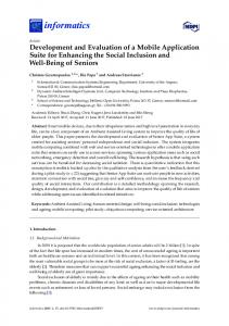
The time needed to reduce the light intensity to e-1 (36.8%) of its original value is defined as the prompt fluorescence decay time (τ). By measuring the decay time as a function of temperature, the phosphor can be calibrated. Exposed ZnS:Mn paint samples were placed in a Thermolyne 46900 furnace at a 45° angle with respect to the top and back walls as shown in Figure 1. Light from a LSI 337-NDS pulsed nitrogen laser was directed through the furnace top and was incident on the painted sample. The pulse frequency of the laser was approximately 10 Hz. Emitted fluorescence from the sample was then collected using a quarter inch diameter glass rod placed directly in front of the sample. A Hamamatsu H5783 photomultiplier tube (PMT) was placed directly at the end of the glass rod. A 590 nm narrow band pass filter was positioned between the PMT and the end of the glass rod to remove stray light. The measured potential from the PMT was displayed using a Tektronix TDS 320 digital oscilloscope. The TDS-320 oscilloscope was synchronized to the internal clock of the LSI laser. A computer-based LabVIEW virtual instrument collected and stored signals (using a GPIB interface) that were averaged over thirty-two laser pulses. A type K thermocouple was used to monitor the sample temperature. Measurements of decay time were initially taken at room temperature (approximately 25 °C), and recorded every 25 °C until temperatures of 350 °C were achieved.
2 American Institute of Aeronautics and Astronautics
Figure 1. Temperature calibration experimental arrangement.
IV. Triboluminescence Impact Detection Triboluminescence (TL) is light produced while striking or rubbing two pieces of a material together. Sir Francis Bacon first studied it 400 years ago and is basically defined as light from friction, since the term comes from the Greek tribein, meaning "to rub," and the Latin prefix lumin, meaning "light"10,11. Most crystals will emit light when fractured. Since most inorganic phosphors have a crystalline structure, they should emit TL. One phosphor, ZnS:Mn, has often been noted for its TL. To develop an effective phosphor based sensor, the relationship between TL intensity and impact velocity for ZnS:Mn or any other material must be quantified. A phosphor painted sample was mounted in a custom built drop tower. A 130 g steel ball was positioned at a known height above the sample. The ball was then released and allowed to drop onto the sample. Light from the sample was collected using a filtered photomultiplier tube (PMT). Voltage signal from the PMT was collected using a digital oscilloscope in single sequence mode. The waveform was then saved for later evaluation. By varying the drop height, different impact energies were obtained. Once the data was collected the intensity of the TL emission was plotted versus the impact energy to form the calibration curve.
V. Half Brightness Dose and Radiation Effects For more than a century, phosphors that emit visible light when exposed to ionizing radiation have been used for a variety of scientific and engineering purposes. These materials exhibit a large fluorescence efficiency that makes them an effective accelerator beam detector or positioning system. Any phosphor used for this purpose will be exposed to large fluences of beam radiation. This candidate material must be able to withstand such fluences with a minimal reduction of fluorescence. The expression “half brightness fluence" (N1/2) was coined as a consistent figure of merit to evaluate the effectiveness of a material to emit fluorescence as a function of exposure. N1/2 was defined as the amount of exposure needed to reduce the fluorescence efficiency to one half of its original value. Birks and Black showed experimentally that the fluorescence efficiency of anthracene bombarded by alphas varies with total fluence as:
I = I0
1 N 1+ N1/2
,
3 American Institute of Aeronautics and Astronautics
(2)
where I, I0, N, and N1/2 represent the fluorescence intensity, initial fluorescence intensity, total incident particle fluence, and the half brightness fluence respectively12. The units of I and I0 are related to the number of fluorescence photons interacting with the detector. When plotting the reciprocal of the light ratio (I0/I) versus proton fluence, the resulting curve is linear with the slope equal to the inverse of N1/2. Paint samples were exposed to 3 MeV protons using the 5SDH-2 tandem Pelletron accelerator, located on the campus of Alabama A&M University at the Center for Irradiation of Materials (CIM). Samples for irradiation were mounted on a four-sided holder located in the implantation beam line at CIM. A total of three samples can be irradiated before opening the chamber to atmospheric pressure. The remaining fourth side of the CIM holder was left empty to periodically adjust the incident current. A current integrator was used to measure total collected proton charge during each irradiation sequence. The entire holder was biased to ~200 V to minimize secondary electron emission. The incident proton beam was randomly scanned over an aperture positioned just upstream of the sample irradiation position. The target beam spot was measured to be circular with an irradiation area of 460 mm2. Scanning a random proton beam over the aperture resulted in a reasonably uniform fluence (± 6%) to the sample surface. Pressure in the irradiation chamber was measured to be less then 10-6 torr for the entire test sequence. A beam scan duty factor of 50% was used for this research.
VI. Results To determine the effect of 3 MeV proton fluence on the fluorescence decay time, a ratio [r(T)τ] was defined for a given temperature as
r(T) τ =
τ(T) r , τ(T)u
(3)
where τ(Τ)r is the decay time for the proton irradiated sample and τ(Τ)u is the decay time for the unirradiated sample. Please note that that the decay time ratio is calculated for 3 MeV proton fluences to 1.35x1014 mm-2 at several given temperatures, in this case 100, 150, and 200 °C. ZnS:Mn paint samples irradiated to different fluences were placed into a calibration furnace. The fluorescence decay time was then measured in-situ as a function of temperature. Figure 2 shows plots of the fluorescence decay time ratio as a function of 3 MeV proton fluence collected at 100 (Figure 2A), 150 (Figure 2B), and 200 °C (Figure 2C). Figure 2D shows a plot of fluorescence decay time as a function of temperature for samples exposed to proton fluences of zero (unirradiated) and 8.35 x 1012 mm-2. In general, Figure 2 shows that ZnS:Mn paint samples exposed to larger proton fluences tended to have smaller decay times. Table 1 shows the results of calculated least squares fits for the data shown in Figures 2A, 2B, and 2C. Table 1 indicates that the ZnS:Mn paint slopes from the three temperature cuts shown in Figure 2 are nearly identical. The fact that the slopes are similar implies that the decay time ratio is dependant only on fluence and not with temperature. This result demonstrates the potential of using phosphors to measure protons in space. Table 1. Least squares fit data for ZnS:Mn decay time ratios. Temperature Absolute Slope Intercept Correlation (°C) (x10-2 mm2) Function (R2) A 100 4.231 0.879 0.873 B 150 4.745 0.934 0.964 C 200 5.237 1.028 0.984
Plot
ZnS:Mn is a well known TL material so it is not surprising that it responds well to low velocity impacts7. For low velocity testing, a drop tower device was developed to vary the impact energy of a steel sphere. The impact energy was controlled by increasing the height of the sphere of above the test specimen. To function in the space environment, a sensor or in this case a sensing material must be able to survive the ionizing radiation found outside of Earth’s atmosphere. With this in mind, preliminary measurements were completed during the summer of 2004.
4 American Institute of Aeronautics and Astronautics
A
B
C
Figure 2. Variation in fluorescence decay time as functions of both fluence (A,B,C) and temperature (D). A paint consisting of the PPMS polymer and ZnS:Mn powder was air brushed on three 1 x 1 inch square aluminum samples. One of these samples was irradiated with a 3 MeV proton fluence of 2.27 x 1013 mm-2 (about 0.25 N1/2) using the 5SDH-2 Pelletron accelerator at Alabama A&M University. A second paint sample was used as a control and was not irradiated with protons. The TL yield (output voltage from the PMT) as a function of impact kinetic energy was measured for both the unirradiated and irradiated paint samples. Impact kinetic energies of 51 to 710 mJ in 26 mJ increments were used for these measurements. Figure 3 shows results from these measurements. Individual lines shown in Figure 3 represent a regression fit to each set of data. It should be noted that TL intensity clearly increases with impact energy for both the un-irradiated and irradiated samples. However, the relative TL yield for both samples is not self-consistent primarily due to variations in how each sample was clamped to the drop tower for measurement. The slope for the irradiated ZnS:Mn paint is considerably less than was measured for the un-irradiated sample, indicating that 3 MeV proton bombardment decreased TL yield. Additional research will be completed to further quantify these results. The third unirradiated ZnS:Mn and PPMS sample was used to determine the effect of repeated impacts on the TL yield at a given impact energy. Results for a projectile impact energy of 31 mJ are shown in Figure 4. The smooth curve is the best-fit line for the accumulated data. Results show that after twenty impacts, the PMT output potential dropped to about 6 V. Repeated impacts reduces the number of undamaged fluorescence centers in the ZnS:Mn, which also reduces the corresponding TL yield. This phenomenon is an important consideration when designing an impact sensor. Repeated impacts will reduce the ability of the sensor to generate TL and increase the probability of errors into the system.
5 American Institute of Aeronautics and Astronautics
Fluence 13 -2 (x 10 mm )
Slope (V/J)
Correlation Factor (R2)
0 2.27
24.94 15.59
0.9887 0.8923
Figure 3. Plot of PMT signal output as a function of projectile impact kinetic energy for ZnS:Mn.
Figure 4. TL yield versus drop number for a ZnS:Mn paint sample with an impact kinetic energy of 31 mJ.
6 American Institute of Aeronautics and Astronautics
VII. Conclusions This research has shown the possibility of using phosphors as the basis for multiple sensors, including: temperature, impact and radiation fluence. While the material selected is not the most radiation resistant known, it does indicate the path that will be needed to select a material for these sensors. Radiation fluence has been shown to reduce not only the photo-induced intensity of the emission, but also the fluorescence decay time of the material, and the impact-induced emission. This information is crucial to the proper development of a space based sensor suite. It will help to determine selection and location criteria. It is also interesting to note that some amount of damage can be annealed from the sensor material.
VIII. Acknowledgements The authors are grateful for the financial support provided by the U.S. Department of Energy (DOE). Research sponsored by the Laboratory Directed Research and Development Program of Oak Ridge National Laboratory (ORNL), managed by UT-Battelle, LLC for the DOE under Contract No. DE-AC05-00OR22725. Accordingly, the U.S. government retains a nonexclusive, royalty-free license to publish or reproduce these documents, or to allow others to do so, for U.S. government purposes. The Louisiana Education Quality Support Fund (LEQSF) using grant LEQSF (2000-03)-RD-A-39 provided additional support for this research. The authors would also like to thank the management and researchers at the Alabama A&M University Center of Irradiation of Materials for providing accelerator beam time to complete this research.
IX. References 1.
A.C. Tribble, “The Space Environment: Implications for Spacecraft Design”, Princeton University Press, Princeton, NJ, 2003. 2. S.W. Allison and G.T. Gillies, "Remote Thermometry with Thermographic Phosphors Instrumentation and Applications”, Rev. Sci. Instrum, 68 (7), 2615-2650, 1997. 3. S.W. Allison, M.R. Cates, S.M. Goedeke, W.A. Hollerman, F.N. Womack, and G.T. Gillies, “Remote Thermometry With Thermographic Phosphors: Instrumentation and Applications”, Chapter 4, Handbook of Luminescence, Display Materials, and Devices, Volume 2: Inorganic Display Materials, Edited by H.S. Nalwa and L.S. Rohwer, American Scientific Publishers, 187-250 (2003). 4. I. Sage, et al.; Embedded Triboluminescent Structural Damage Sensors, Proc. SPIE 4104, 1-8 (2000). 5. S.M. Goedeke, S.W. Allison, F.N. Womack, N.P. Bergeron, and W.A. Hollerman, “Triboluminescence and its Application to Space-Based Damage Sensors”, Proceedings of the Propulsion Measurement Sensor Development Workshop, Huntsville, AL, May 14, 2003. 6. W.A. Hollerman, G.A. Glass, and S.W. Allison, “Survey of Recent Research Results for New Fluor Materials”, Materials Research Society Symposium Proceedings, vol. 560, pp. 335-340, 1999. 7. F.N. Womack, N.P. Bergeron, S.M. Goedeke, W.A. Hollerman, and S.W. Allison, “Measurement of Triboluminescence and Proton Half Brightness Fluence for ZnS:Mn”, IEEE Transactions On Nuclear Science 51 (4): 1737-1741 2004. 8. W.A. Hollerman, S.M. Goedeke, N.P. Bergeron, C.I. Muntele, S.W. Allison, and D. Ila, “Effects Of Proton Irradiation On Triboluminescent Materials Such As ZnS:Mn,” Proceeding of CAARI, Fort Worth, TX October 10-14, 2004. 9. N. P Bergeron, S.M. Goedeke, W.A. Hollerman, C.I. Muntele, S.W. Allison, and D. Ila, “Evidence of Annealed Proton Damage From a ZnS:Mn-Based Phosphor Paint,” Proceedings of the Space Technology and Applications International Forum, Alburquerque, NM February 13-17, 2005. 10. A.J. Walton, “Triboluminescence”, Adv. Phys., vol. 26 (6), pp. 887-948, 1977. 11. L. Sweeting, “Triboluminescence With and Without Air”, Chem. Mater., vol. 13 (3), pp. 854-870, 2001. 12. J.B. Birks and F.A. Black, “Deterioration of Anthracene Under α Particle Bombardment”, Proc. of the Phys. Soc. (Lond.), vol. A64, pp. 874-875, 1951.
7 American Institute of Aeronautics and Astronautics