EEG. Data. Stimulus codes ... EEG signal and combines with stimulus code before sending them to .... In order to achieve lower FIT, accurate timer is needed.
Proceedings of the 2005 IEEE Engineering in Medicine and Biology 27th Annual Conference Shanghai, China, September 1-4, 2005
P300 Brain-Computer Interface Design for Communication and Control Applications Chaunchu Wang, Cuntai Guan, Haihong Zhang Institute for Infocomm Research, Singapore 119613 E-mail: {ccwang, ctguan, hhzhang}@i2r.a-star.edu.sg Abstract: This paper introduces the design of a P300-based Brain-Computer Interface (BCI) system. Based on this system, two applications are implemented: a word speller and a remote control device, which are to assist physically disabled people to communicate and control. A number of specific implementation techniques are proposed to achieve good performance in terms of accuracy and reliability. The word speller can achieve a spelling rate of up to 4-6 letters per minute, while both applications achieve 99% accuracy in our experiments with healthy subjects.
B
I. INTRODUCTION
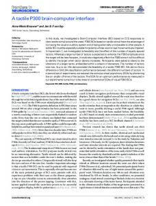
rain-computer Interface (BCI) shows a great potential to provide new channels for physically disabled people, especially lock-in patients, to communicate and interact with the outside environments. With BCI, they can control devices or browse internet, which helps improve their life quality. A BCI system records brainwave signals, detects patterns that are correlated to specific brain activities (such as responses to stimuli or imagination of motor movement, etc.), transfers these patterns into control signals and carries out actions to accomplish the subject’s intention. A good review of BCI can be found in [1]. P300 signal is one of the typical patterns captured from the Electroencephalogram (EEG) at the central cortex. It is a positive component occurring about 300ms after a stimulus. Studies showed that P300 is quite robust [2]. EEG-based BCI is non-invasive, so it is more easily to be accepted. Recently, we proposed improvements to achieve better accuracy and information transfer rate [3]. For a real-world application system, there are many specific techniques need to be developed in order to achieve good performance in terms of reasonable speed and high accuracy. In this paper, we introduce the design of a P300 based BCI, followed by two applications based on this core technology. Specific techniques are highlighted. II. SYSTEM DESIGN The system structure of a BCI system is shown in Fig. 1. It consists of four modules: data acquisition, signal processing, system controller and command output. We implemented these modules on Microsoft Windows XP, in .Net C++ and C#. A. EEG Data Acquisition The device we used for study is NeuroScan SysAmps2. It 0-7803-8740-6/05/$20.00 ©2005 IEEE.
Data Acquisition
Visual Stimuli Feedback
Signal processing
System Controller
Device
Command Output
Fig. 1. P300 based Brain-computer Interface system consisting of four modules: data acquisition module recording EEG data from the brain; signal processing module extracting features from EEG data and converting recognized patterns into commands; command output module converting commands into control signal to control devices; system controller module coordinating all other modules, and also generating visual stimuli to the testing subject.
can record 64 channels of EEG data from electrodes placed according to the extended 10-20 system. After evaluation, we select 24 channels. A further feature election can be used to reduce the number of channels so that it is more convenient for preparation. As an alternative, 32-channel NuAmps can also be used for P300 BCI if mobility is required, as SysAmps2 is still a bulky machine with higher resolution. Nuamps is portable, easy to install and configure. It powers on the USB port that is also used for data transfer. Fig. 2 shows the hardware configuration of the data acquisition module. Stimulus codes are sent to EEG amplifier through the parallel port. The EEG data the computer received includes a special channel made of the stimulate codes, called events. This is important because normally there is a delay between a stimulus and the corresponding EEG signal being received. This delay may vary depending on the computer configuration and runtime tasks. The event channel helps to synchronize the stimulus and the corresponding EEG data. Analog potential data
Stimulus codes EEG Data
Fig. 2. Hardware components: Nuamps takes analog signal from EEG cap and stimulus codes from computer. It amplifies, digitalizes the EEG signal and combines with stimulus code before sending them to the computer.
Scan acquisition software is run on the computer to receive EEG data from NeuroScan amplifiers through USB port. The sampling rate is set to 250 Hz. Data acquisition module connects to the server through TCP/IP socket. It also records the EEG data into files on the local hard disk for offline analysis.
When the number of rounds is reached, a decision is made to find the best stimulus with the highest score. According to the decision criteria, if the result is not acceptable, system discards the data of the earliest rounds, reads in new rounds of data and continues this process, until a satisfying result is reached.
B. Signal Process The signal process module consists of a library of EEG data processing functions. It controls the signal processing workflow. They are implemented in C++. Every round of epochs goes through all or some of the following processing procedures according to system configuration. 1) Artifact removal. Two EOG channels (horizontal and vertical) are used to subtract EOG from all other channels. 2) Channel selection. Select the EEG data from the predefined channels for processing. 3) Epoch data segmentation: The time frame for the segmentation in P300 BCI is from 150ms to 500ms. 4) Band-pass filtering. Frequency band is set from 0.5Hz to 25Hz. 5) Epoch data Down-sampling. The EEG signal is downsampled by 5 fold, so a more compact feature vector is obtained for classification. 6) PCA (Principle Component Analysis). PCA is used to reduce the number of Channel dimensions. After PCA, with fewer channels selected, feature size is further reduced. 7) Dynamic-vector for feature extraction. A dynamic vector is appended to the feature vector to construct a new dynamic feature data for classification. After using this method, error rate is significantly reduced [3]. 8) SVM classification. The SVM model is created by the training program. The classification decision usually needs to take ensemble average over several trials. 9) Decision for result output. The decision process is shown in Fig. 3.
C. System Controller System Controller module shows a virtual keyboard (for word speller) or a control panel (for TV remote control) to the subject, and flashes the buttons on the panel to elicit P300 on a subject. Because of the GUI design, this module is implemented in C#. The paradigm in [3] is adopted because of its flexibility and higher accuracy. The System Controller also controls the workflow of all other modules. When system is started, it calls the data acquisition module to initialize and collects configuration information, such as number of data channels, number of selected channels, sampling rate, data size and resolution, from Neuroscan server; then starts the signal processing module. C# is a managed language. Because of the historic reason, all other modules are written in unmanaged C++. So a managed C++ library is built to wrap underling unmanaged C++ functions. Fig. 4 shows the coordination between the system controller, data acquisition module and signal processing module. It is implemented with Windows events.
Flash, send stimuli
No, next
Is set?
Take result Set event
Read in Epoch
Read epoch and process
Result Ready Result Taken
Set event Get result
Is set?
No, wait
Yes, cont. N Is buffer full?
Yes, wait Is set?
Y Shift buffer
Calculate Decision Score
N Threshold Reached? Y Result accepted. Fig. 3. Decision flow: a result is either rejected or accepted according to a predefined threshold. If rejected, system will shift its buffer window by removing the oldest records and take in new records, and redo the decision making process.
No, cont.
Data acquisition, Stimuli if stimulus queue Queue Set event is too long, set the event.
Fig. 4. System controller (left) coordinates with other two modules with 3 events. It synchronized with the processing module (top right) with “Result Ready” and “Result taken” events; and it synchronizes with the data acquisition module (bottom right) with “Stimuli queue” event so that there should not be too many epochs in the waiting queue.
D. Command Output The command output module executes the action the subject wants to do. Different applications have different command output module. For a word-speller, the output module print the letter that the subject is “thinking” into the
document window; for a TV remote control, the output module is an IR (Infrared) remote transmitter which sends control signal to a TV set. III. APPLICATIONS With the core system we constructed above, we have developed two applications: a word speller and a TV remote control. A. Virtual Keyboard Word Speller A virtual keyboard system is developed, which is meant for physically disabled to input a text document into computer. Fig. 5 shows the detailed GUI design. The upper half of the screen is the editing area, and the lower half part of the screen is a virtual keyboard.
Fig. 5. The GUI design of Brainy Communicator, a Single Display virtual keyboard for word spelling, includes 44 keys, 40 of them are letter keys and 4 control keys. Normally six rounds of trials can produce reasonably good results, which takes about 10 seconds.
On the bottom left of the keyboard, there is one special button called On/Off. This is originally designed to activate and deactivate the system. When the system is deactivated, no letter will be input into the window, no matter what is the processing result. The intention is to give the user a means to turn off the system and have a rest after some time of working on it. With our new decision making system, if the user is not attentive to the virtual keyboard, the result will be rejected. B. BCI Remote-Control This application is designed to allow a user to control a TV set through a virtual control panel displayed on the computer screen. The design of the virtual control panel is shown in Fig. 6. We built an IR remote control device connected to computer through the serial port. The commands from the BCI remote control include the control of TV channels, power on/off, and audio volume. A tool is designed to learn the IR patterns from any real TV remoter. IV. SPECIAL IMPLEMENTATION TECHNIQUES In the development of the application systems, we addressed several special implementation techniques in
Fig. 6. BCI Remote Control, a virtual TV remote control. It has 18 buttons: power on/off, channel up, audio/mute, volume down, channel down, volume up, 10 digits for channel selection, single/double digits switch, TV/AV switch. Experiments show that a user can issue a command through this controller within 4 seconds.
order to achieve good performance. A. Stimulus Generation Stimulus sequence must be randomly generated. In the EEG data we obtained from the electrodes on the brain, the P300 in single trial is actually very weak and hard to be detected. So in practice, an ensemble average over several trials is necessary. In each round, buttons flash one by one in a random sequence. The time interval between subsequent flashes can be as small as 30 milliseconds. An epoch data we take for analysis lasts for around 350 (150 – 500) milliseconds, which means a P300 pattern may appear in several segmented epochs. So with only a single trial of EEG, we definitely cannot reliably detect which stimulus evoked P300 signal. The ensemble average of epoch data over a number of rounds solve this problem: after averaging, only the stimulus that evokes the P300 response will consistently includes the P300 pattern, so P300 signal will be enhanced. The interval time between any two consequent flushing of the same button should not be too short. To help the subject to focus at the required button, we let the subject count the number of flashes of button he/she is focusing on. In the generation of the random sequence, we need to make sure that the time interval between subsequence flashing of the focused button must not be less than a predefined value, normally defined as 300-400 milliseconds. If the time is too short, subject may miss some flashes. This causes weak or missing P300 patterns in the corresponding epoch data which should have. The system should avoid that neighbor buttons are too close in the flushing sequence. Otherwise, if one of the surrounding buttons is the one the subject is looking at, the interference will also affect the results due to distractions. All these constraints are considered in the design of the algorithm of random generation of the flashing sequences. B. Button Intensification Overlapping This is a special technique to assist us to achieve higher spelling rate for word speller. The effective way of
increasing spelling rate is to reduce the intensification duration of each button. Obviously, there must be limit for such a strategy. When the duration is reduced to a reasonably small value, say 30 ms, the flash of each button is too short to be reliably captured by eyes. To solve this problem, we proposed Button Intensification Overlapping (BIO) strategy – successively flashed buttons are partially overlapped in intensification. Fig. 6 shows an example, where two buttons are highlighted at the same time. This way, we achieve a good compromise between accuracy and speed. The idea of BIO is to reduce flash interval time (FIT) while keeping button intensification time (BIT) unchanged. The word speller we designed in [2] used a FIT of 60 milliseconds. For the case of using 8 rounds of intensification per letter and 44 buttons, the spelling speed is around 21 seconds per letter (60 * 44 * 8 = 21120). If FIT is reduced to 30 milliseconds, the spelling speed is reduced to around 10 seconds per letter. And if FIT is 20 milliseconds, the spelling speed will be 7 seconds per letter. Normal display method is that a letter is intensified only after the previous letter goes back to non-intensification. In that case, BIT is equal or less than FIT. When FIT time is reduced, if we use the normal display method, BIT is also reduced. Then it will certainly affect the classification accuracy because the button flashes too fast. But now, since we keep BIT unchanged while reducing the FIT time, our preliminary experiments show that we can achieve comparable accuracy for FIT at 60ms and 30ms while keeping BIT as 60ms. This is a simple yet promising way of increase the information transfer rate. We define an overlapping degree as follows: D = BIT / FIT Fig. 7 shows an example of overlapping with D = 3. From this figure we can see, after 40 ms, there will be always 3 buttons intensified at the same time.
When one writes a BCI based on Windows system, the default timer resolution on Windows is 15 milliseconds. We therefore need to use Windows Multimedia timer, which can be configured to set more accurate timer resolution according to our requirements, say 1 millisecond. Interested reader can refer to “Multimedia Timers” in MSDN documentation. Function “timeBeginPeriod” in “winmm.dll” sets timer resolution, “QueryPerformanceCounter” and “QueryPerformanceFrequency” are used to get the system time in milliseconds. V. CONCLUSION We have implemented a robust and reliable BCI system. In order to achieve high information transfer rate without compromising accuracy, we developed several implementation techniques. The Button Intensification Overlapping technique, together with the specially designed button flashing sequence generation algorithm and high resolution timing technique, helped significantly improve the spelling and control speed. With these techniques, the word speller has achieved a spelling rate of 4-6 letters per minute, and the remote-control can issue a command within 4 second, while both keeping the accuracy close to 99%. REFERENCES [1] [2] [3]
[4]
[5]
Button 1: Button 2:
[6]
Button 3: Button 4: Time (ms)
0
20
40
60
80
100 120
Fig. 7. Key intensification overlaying, FIT=20ms, BIT=60ms. From 40ms, there are 3 keys intensified (highlighted) on the virtual keyboard at the same time.
Our preliminary experiments show we can achieve good performance for D=2 and D=3, but not for higher value, because it can be seen when D is higher, more simultaneous intensified buttons actually cause more distractions. C. High Resolution Timing In order to achieve lower FIT, accurate timer is needed.
[7]
J. R. Wolpaw, N Birbauner, D. J. McFarland, G. Pfurtscheller, T. M. Vaughan, “Brain-computer interfaces for communication and control”, Clinical Neurophysiology 113 pp.767-791, 2002 B. H. Jansen, A. Allam, P. Kota, K. Lachance, A. Osho, K. Sun “An Exploratory Study of Factors Affecting Single Trial P300 Detection”, IEEE Trans. Biomed.Eng., vol. 51, pp. 975-978, 2004 C. T. Guan, M. Thulasidas, J. K. Wu, “High Performance P300 Speller for Brain-Computer Interface”, presented at IEEE International Workshop on Biomedical Circuits and Systems, 1-3 Dec, 2004, Singapore M. Kaper, U. Grossekathoefer, T. Lingner, H. Ritter, “BCI Competition 2003 – Data Set IIb: Support Vector Machines for the P300 Speller Paradigm”, IEEE Trans. Biomed. Eng. vol. 51 , pp. 1073-1076, 2004 N. Xu, X. R. Gao, B. Hong, X. B. Miao, S. K. Gao, F. S. Yang, “BCI Competition 2003 – Data Set II b: Enhancing P300 Wave Detection Using ICA-Based Subspace Projections for BCI Applications”, IEEE Trans. Biomed.Eng., vol. 51, pp. 1067-1072, 2004 G. Schalk, D. J. McFarland, T. Hinterberger, N. Birbaumer, J. R. Wolpaw, “BCI2000: A General –Purpose Brain-Computer Interface (BCI) System”, IEEE Trans. Biomed.Eng., vol. 51, pp. 1034-1043, 2004 J. F. Borisoff, S. G. Mason, A. Bashashati, G. E. Birch, “BrainComputer Interface Design for Asynchronous Control Applications: Improvements to the LF-ASD Asynchronous Brain Switch”, IEEE Trans. Biomed.Eng., vol. 51, pp. 985-992, 2004