JOURNAL OF APPLIED PHYSICS
VOLUME 93, NUMBER 10
15 MAY 2003
Effect of microstructure on the oscillating interlayer coupling in spin-valve structures J. C. S. Koolsa)
Process Equipment Group, Veeco Instruments, 3100 Laurelview Court, Fremont, California 94538
A. J. Devasahayam, K. Rook, and Chih-Ling Lee
Process Equipment Group, Veeco Instruments, 1 Terminal Drive, Plainview, New York 11803
M. Mao
Process Equipment Group, Veeco Instruments, 3100 Laurelview Court, Fremont, California 94538
�Presented on 14 November 2002� It has been well established that the interlayer coupling in a spin valve is well described as a sum of terms associated with pinholes, magnetostatic �Ne´el�, and oscillating exchange interlayer coupling ��OXC� or Ruderman–Kittel–Kasuya–Yosida�. We experimentally studied the effect of interface roughness on the OXC term. We systematically varied the microstructure by variation of the sputtering geometry, the sputtering pressure, the seed layer and by application of low-energy ion bombardment at the interfaces �‘‘beam treatment’’�. It is found that smoothening the stacks leads to a stronger OXC, both when suppressing long-range ��200 Å� and short-range ��20Å� roughness. Ne´el coupling on the other hand, is found to be more sensitive to long-range waviness. © 2003 American Institute of Physics. �DOI: 10.1063/1.1555798�
I. INTRODUCTION
where h is the amplitude of the roughness. It was shown in Ref. 8 that Eq. �2� can be modified straightforwardly to account for the effects of finite magnetic film thickness. The parameter J 1 was studied extensively by model experiments and theory for the Co/Cu�111� system �see e.g., Ref. 11 for a review�. Theoretical calculations which assume a perfect interface yield values of 0.59 to 0.67 mJ/m2. Experimental values on the other hand, yield a larger spread, i.e., from 0.4 mJ/m2 to 1.1 mJ/m2. This observation is consistent with the very rapid degradation of the interference phenomenon by the introduction of interface roughness. An expression describing this phenomenon was put forward by Levy, Maekawa, and Bruno �LMB�:12
It is well established in literature �Refs. 1–9�, that the interlayer coupling in a spin valve is a sum of contributions from pinholes, oscillating interlayer exchange ��OXC�; also known as Ruderman–Kittel–�Kasuya�–Yosida� coupling due to conduction electron reflection at the internal interfaces, and a ferromagnetic magnetostatic coupling term due to magnetic poles created by waviness of the magnetic– nonmagnetic interface �Ne´el coupling�. In the regime where the copper spacer is continuous �i.e., pinholes can be ignored�, this can be written as H int�H OXC�H Ne´el� �N exp
�
J1 2 M s t F t Cu
�
�2 � &t Cu . �
sin
�
2 � � t Cu� � � �
�
2 2
J 1 �J 0 e �2k F� LMB,
where J 0 is the amplitude in the case of perfect interfaces, and � LMB is the standard deviation associated with the interface roughness. The combination of Eqs. �1�–�3� allows one to describe the coupling in terms of some intrinsic �‘‘fixed’’� parameters (J 0 ,M s ,t F ,t Cu ,k F ,...) and some parameters accounting for microstructural imperfections (h,�, � LMB). The microstructural imperfections in sputtered stacks can be divided in three categories �in order of decreasing lateral correlation length�.
�1�
Formula �1� is the aliased form of the oscillating coupling �see e.g., Refs. 10 and 11�. The fixed parameters t Cu , t F are the Cu and free layer thicknesses, M s is the free layer magnetization, and k F is the wavevector of electrons at the Fermi level ��1.25 Å�1 for Cu�111��. The variable parameters describing the coupling are the amplitude J 1 of the interlayer coupling at t Cu�1 nm, the aliased period and phase ��, ��, and the prefactor N, and the wavelength � of the Ne´el coupling. In the case of infinite magnetic film thickness �classic Ne´el model�, this term N is given as N�
� 2h 2� 0M s , 2�t F
�1� The polycrystalline columnar grain structure: The grain size and associated roughness are affected by the energy and angular distribution during sputtering1,13 �with higher energy and collimated deposition giving smoother films�, the use of seed layers,9 and the cleanliness of the system.14 The lateral correlation length is typically in the range 50–250 Å. �2� Steps due to island growth: Fundamental studies of the growth of Cu, Co, and the like have revealed15,16 the occurrence of island growth, rather than layer-by-layer
�2�
a�
Electronic mail:
[email protected]
0021-8979/2003/93(10)/7921/3/$20.00
�3�
7921
© 2003 American Institute of Physics
Downloaded 05 Jun 2013 to 117.211.119.200. This article is copyrighted as indicated in the abstract. Reuse of AIP content is subject to the terms at: http://jap.aip.org/about/rights_and_permissions
7922
Kools et al.
J. Appl. Phys., Vol. 93, No. 10, Parts 2 & 3, 15 May 2003
growth, and consequently surface roughness associated with the steps. We found the lateral correlation length of this roughness to be in the range 10–30 Å in our films �high-resolution transmission electron microscopy�. The key to suppression of this mechanism is to facilitate diffusion over the Ehrlich–Schwoebel barrier. This can be accomplished by exposure of the surface to surfactants such as O2 or low-energy ion bombardment.16 �3� Alloying at the interface due to collisional intermixing: High kinetic energy of the metal atoms can lead to formation of an interfacial alloy layer.1 It is the aim of this article to systematically study the dependence of the oscillating interlayer coupling on the first two aspects of the microstructure. II. EXPERIMENT
Series of spin-valve stacks with the generic configuration seed/Pt50Mn50 /Co90Fe10 /t Cu Å Cu/Co90Fe10 /Ni81Fe19 / Ta, where t Cu typically varies from 18 Å to 40 Å were deposited by dc-magnetron sputtering in two different geometries �‘‘planetary’’ and ‘‘static’’�. The most significant difference between these geometries lies in the angular distribution of atoms arriving at the film. Through the use of smaller targets, flux-blocking shields and larger target-tosubstrate spacing, the acceptance angle under which the wafer sees the target is reduced from about �60° �static� to �25° �planetary�. Thus, atoms arriving at the wafer are expected to be more collimated in the planetary tool. After deposition, the wafers were mag-annealed and low-field magnetoresistance loops were measured in a BH looper. Microstructure was analyzed by atomic force microscopy �AFM�, x-ray diffraction �xRD�, and transmission electron microscopy �TEM�. The experiments can be divided in two main sets. �1� In a first set of experiments, we varied the parameters known to affect the grain structure: Sputtering geometry �static versus planetary�, Ar pressure during sputtering �1 mTorr versus 0.5 mTorr� and seed layer �using either Ta/NiFeCr or NiFeCr/NiFe�. �2� In a second set of experiments, we applied a surface treatment by low-energy ion bombardment to the upper interface of the pinned CoFe layer �‘‘beam treatment’’�. When applied under appropriate conditions, such lowenergy ion bombardment steps are known17–19 to improve the flatness of metallic layers.
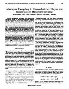
FIG. 1. Interlayer coupling field vs Cu thickness for seed/150 Å PtMn/25 Å CoFe/t Cu Cu/15 Å CoFe/30 Å NiFe/30 Å Ta where �a� Static deposition; Ta/NiFeCr seed, �b� Planetary deposition @1 mTorr; Ta/NiFeCr seed, �c� Planetary deposition @0.5 mTorr; Ta/NiFeCr seed; and �d� Planetary deposition @0.5 mTorr; NiFeCr/NiFe seed.
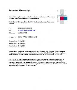
Figure 2 shows the interlayer coupling versus t Cu for three sets of spin valves with increasing beam treatment time. The data are ordered in sequence of improving microstructure. �a�
�b�
�c�
Series 1a, 1b, and 1c are intended to have decreasing roughness amplitude due to a decrease in microshadowing during growth. This is confirmed by their respective AFM roughness values of R a �4.2 Å, 3.1 Å, and 2.7 Å. Series 1d is intended to have an increased grain size in comparison with 1c due to the use of a different seed layer. This is confirmed by a strong increase of the �111� peak height in XRD �160 cps to 8000 cps�. Series 2a through 2c show a slight reduction of R a �from 4.2 Å to 3.1 Å�. Cross section TEM indicates that there is no significant difference in their granular structure.
During all of those experiments, great care was taken to ensure that the individual layer thicknesses �in particular the Cu thickness� did not vary as a result of the process variation. III. RESULTS AND DISCUSSION
Figure 1 shows the interlayer coupling versus t Cu for four sets of spin valves, where the granular structure was manipulated through sputtering geometry, sputtering pressure, and seed layers. �Detailed conditions are given in the caption.�
FIG. 2. Interlayer coupling field vs Cu thickness for Ta/NiFeCr/175 Å PtMn/30 Å CoFe/t Cu Cu/10 Å CoFe/20 Å NiFe/10 ÅCu/30 Å Ta deposited in the static tool which were subjected to 0 s �a�, 30 s �b�, and 60 s�c� of beam treatment.
Downloaded 05 Jun 2013 to 117.211.119.200. This article is copyrighted as indicated in the abstract. Reuse of AIP content is subject to the terms at: http://jap.aip.org/about/rights_and_permissions
Kools et al.
J. Appl. Phys., Vol. 93, No. 10, Parts 2 & 3, 15 May 2003
7923
TABLE I. Fit parameters for Eqs. �1�, �2�, and �3� to describe the lines in Figs. 1 and 2. Dataset 1a 1b 1c 1d 2a 2b 2c
h ��
� ��
J 1 �mJ/m2�
� LMB ��
� ��
� ��
2.35�0.1 2.14�0.1 1.77�0.1 1.40�0.2 1.45�0.1 1.59�0.1 1.56�0.1
76�10 70�10 70�10 400�100 106�20 169�30 169�30
0.06 0.21 0.24 0.34 0.095 0.17 0.27
0.74�0.1 0.36�0.1 0.31�0.05 0.21�0.05 0.62�0.1 0.44�0.1 0.28�0.05
11.5�0.1 11.6�0.1 11.3�0.1 11.7�0.1 11.9�0.1 12�0.1 12�0.1
10�0.1 9.00�0.1 10.6�0.1 11.15�0.1 11.4�0.1 8.65�0.1 9.8�0.1
In both datasets, the experimental data show a range of behaviors from a Ne´el-dominated behavior �monotonous decrease of coupling with t Cu ; 1a, 2a� for the rougher films, to a behavior dominated by the OXC �1d, 2c� for the smoother films. Furthermore, it can be observed clearly that the minimum of the oscillation is not at the same position, indicating there is a phase shift in the oscillating term. We then compared both sets of data to Eqs. �1a�, �2�, and �3�, assuming J 0 �0.65 mJ/m2 , obtaining the fit parameters shown in Table I. We did not consider datapoints with values of H int�40 Oe, since such high values might be an indication of the presence of ferromagnetic pinholes. Some of the trends seen in Table I are consistent with earlier work:1,6,9,11 �a�
�b�
The trends in the Ne´el parameters �h, �� are found to be in line with microstructural characterization, whereby h is correlated with R a , and � with the x-ray data. All values of the period of the oscillating coupling are similar to earlier work on Co/Cu �111�.
As mentioned herein, smoother films are found to have a stronger oscillating component �increasing J 1 and therefore decreasing � LMB) with increasing smoothness. The correlation between the two roughness parameters h and � LMB deserves some more attention. �a�
�b�
For the values of series 1a through 1d, we find a good correlation between the two parameters �and R a ). Thus, we find that all the different methods to manipulate the grain structure �i.e., seed layers, Ar pressure, and sputtering geometry� affect Ne´el and OXC simultaneously. On the contrary, for series 2a through 2c, we find a significant variation of � LMB , while h remains virtually constant, albeit that there is some change in �.
We suggest that these observations can be explained by the different sensitivity of the two coupling mechanisms for short-range �e.g., 20Å� roughness associated with steps due to island growth: The origin of the oscillating interlayer coupling is in the reflection of conduction electrons at the magnetic/nonmagnetic interfaces. Since the wavelength of conduction electrons in Cu is around 5 Å, one expects that roughness with a lateral dimension similar to, or a few times larger than that wavelength is likely to cause destructive interference. On the other hand, the Ne´el coupling due to these short-wavelength features has a very rapid decay with spacer
thickness, and can be ignored for t Cu�10 Å. Therefore, if beam treatment suppresses island growth, as suggested by molecular-dynamics simulations which we performed,17 it is expected to affect the oscillating interlayer coupling without affecting the Ne´el coupling, as seen experimentally. IV. CONCLUSIONS
We experimentally studied the effect of microstructure on the oscillating interlayer coupling in PtMn-biased bottom spin valves. We systematically varied the microstructure by variation of the sputtering geometry, the sputtering pressure, the seed layer, and by application of low-energy ion bombardment at the interfaces �beam treatment�. It is found that smoothening films results in a stronger OXC coupling, both when suppressing long-range ��200 Å� and short-range ��20 Å� roughness. Ne´el coupling, on the other hand, is only found to be sensitive to long-range waviness for the present spacer thickness range. ACKNOWLEDGMENTS
F. Dahmani, H. Hegde, R. Hempstead, and J. NunezRegueiro are acknowledged for stimulating discussions. 1
J. C. S. Kools, J. Appl. Phys. 77, 293 �1995�. J. C. S. Kools, Th. G. S. M. Rijks, A. E. M. De Veirman, and R. Coehoorn, IEEE Trans. Magn. 31, 3918 �1995�. 3 J. L. Leal and M. H. Kryder, J. Appl. Phys. 79, 2801 �1996�. 4 J. L. Leal and M. H. Kryder, IEEE Trans. Magn. 32, 4642 �1996�. 5 D. Wei and H. N. Bertram, IEEE Trans. Magn. 32, 3434 �1996�. 6 C.-M. Park, K.-I. Min, and K. H. Shin, IEEE Trans. Magn. 32, �1996�. 7 J. C. S. Kools IEEE Trans. Magn. 32, 3165 �1996�. 8 J. C. S. Kools, W. Kula, D. Mauri, and Tsann Lin, J. Appl. Phys. 85, 4466 �1999�. 9 D. C. Parks, P. J. Chen, W. F. Egelhoff, and R. D. Gomez, J. Appl. Phys. 87, 3023 �2000�. 10 P. Bruno, Phys. Rev. B 52, 411 �1995�. 11 M. D. Stiles, J. Magn. Magn. Mater. 200, 322 �1999�. 12 P. Levy, S. Maekawa, and P. Bruno, Phys. Rev. B 58, 5588 �1998�. 13 W. E. Bailey, N.-C. Zhu, and R. Sinclair, and S. X. Wang, Appl. Phys. 79, 6393 �1996�. 14 M. Takahashi, M. Tsunoda, and K. Uneyama, J. Magn. Magn. Mater. 209, 65 �2000�. 15 J. Ferron, L. Gomez, J. M. Gallego, J. Camarero, J. E. Prieto, V. Cros, A. L. Vazquez de Parga, J. J. de Miguel, and R. Miranda, Surf. Sci. 459, 135 �2000�. 16 J. Camarero, J. de la Figuera, J. J. de Miguel, R. Miranda, J. Alvarez, and S. Ferrer, Surf. Sci. 459, 191 �2000�. 17 J. C. S. Kools and A. J. Devasahayam �unpublished�. 18 Y. Miayamoto, T. Yoshitani, S. Nakagawa, and M. Naoe, IEEE Trans. Magn. 32, 4719 �1996�. 19 E. Spiller, Appl. Phys. Lett. 54, 2293 �1989�. 2
Downloaded 05 Jun 2013 to 117.211.119.200. This article is copyrighted as indicated in the abstract. Reuse of AIP content is subject to the terms at: http://jap.aip.org/about/rights_and_permissions