ISSN 1392 – 1215
ELECTRONICS AND ELECTRICAL ENGINEERING ELEKTRONIKA IR ELEKTROTECHNIKA
T 171
2010. No. 7(103)
MICROELECTRONICS MIKROELEKTRONIKA
Integrated Front End Electronics Design for Micromachined Ultrasound Transducers G. Vanagas
Institute of Physical Electronics, Kaunas University of Technology, Savanoriu 271, LT-50131 Kaunas, Lithuania.
D. Viržonis
Kaunas University of Technology Panevezys Inst., dept. of Electric Engineering, Daukanto 12, LT-35212,Panevezys, Lithuania; Phone: +370 687 13551, e-mail:
[email protected]
V. Paukštaitis,, D. Baranauskas
Pacific MicroCHIP Corp. 11949 Jefferson Blvd. #105 Los Angeles, CA90230 USA
S. Červiakov
UAB Medelkom, Graičiūno g. 10, LT-02241 Vilnius, Lithuania Introduction
space; iii) parasitic capacitance of interconnecting leads [6]. Therefore integration of the front-end electronics (containing pulsers, beamformers, switches and preamplifiers) with CMUT array becomes the necessary solution. Heterogeneous integration of the CMUT array and electronic circuit (IC) in a stack with the flip-chip bonding is believed to be advantageous, because of design/manufacturing flexibility and space economy. The general aim of our research was maximizing the signal to noise ratio (SNR) of integrated 2D CMUT-IC microsystem, dedicated to work in a vein visualization and detection device. Requirements of better than 0.3 mm resolution ability in 16x16x20 mm volume, outstanding 3D imaging quality and reasonable energy efficiency determine the research frame. Most of the known solutions of front-end electronics for CMUT devices [7] were built for demonstrational purposes and do not clearly address the signal to noise issues of the entire microsystem. SNR of CMUT-IC microsystem is dependant both on electrical and mechanical noise and on signal damping due to the parasitic electrical parameters. All the SNR reducing factors can be addressed by coordinated design of both microsystem components. Therefore we aimed the investigation of several factors of SNR improvement: i) optimization of CMUT operating point; ii) mechanical design improvement; iii) adjustment of scanning strategy.
The concept of capacitive micromachined ultrasound transducers (CMUT) came within several last decades. The principle of operation of CMUT is basically the same as of well known capacitive speaker/microphone. CMUT device can be drafted as a capacitor with one fixed and one moveable electrode, which is coupled with the membrane of adequate elastic properties. Thanks to the micromachining techniques available today, fabrication of the transducers with frequency range of conventional ultrasound devices (1 – 30 MHz) with precisely predictable characteristics became possible. Main structural materials for making CMUT are silicon and silicon compounds, and there are two proven technologies of fabrication: surface micromachining [1, 2] and bulk micromachining with wafer bonding [3]. Wider fractional bandwidth and better impedance match between the transducer and the surrounding medium are the most important functional advantages of CMUT over the piezoelectric and magnetostrictic ultrasound transducers, while used in medicine diagnostics. One of the most promising application of CMUT concept is the real-time three-dimensional (3D) medicine imaging [4], which is possible only at low resolution, if piezoceramic transducer arrays are used. In contrast, twodimensional (2D) transducer arrays for high resolution real-time 3D imaging can be manufactured within reasonable efforts, if CMUT concept is used [5]. However, due to the high number of transducer elements and small dimensions proper use of such an array becomes challenging: i) small element dimensions lower signal-tonoise ratio; ii) large number of conductors in very limited
Table 1. Initial parameters of CMUT array Parameter Array size Element dimension, µm Cell dimension, μm
117
Value 64x64 250 38
0.3 0.2 0.3 169 2330 0.278
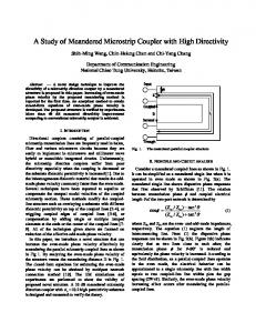
Research methods used Technical specifications determined the size of transducer element to be 250x250 µm. This ensures required resolution at the transducer plane. Operating frequency of 10 MHz ensure required volumetric resolution. Critical dimensions of the CMUT cell were calculated applying electromechanical equivalent circuit method [6, 9]. For the fine-tuning of CMUT cell parameters finite element analysis (FEA) simulation was used, employing earlier developed model [10]. Graphical representation of two dimensional FEA model of single cMUT cell immersed in fluid is shown on Fig. 1. The membrane and electrode were divided by PLANE42 elements, and the vacuum gap was divided by TANS126 elements. The medium was modelled as a cylinder, consisting of FLUID29, with absorbing FLUID29 at the edge. Acoustic mirrors were positioned at the distances of L=0.6 mm and 1.0 mm from cMUT active surface; they were divided by PLANE42 elements. A two mirror design was chosen to make the model more adequate for signal to noise ratio (SNR) simulation [10].
Insulating trench
Solder bump
Fig. 2 Cross section of four CMUT cells depending to different transducer elements, separated by isolation post
CMUT structure with significant isolation capability is placed in between. Membrane cells lateral dimensions were determined as 38 µm square in order a 1.3 µm thick silicon membrane would operate at 10 MHz resonance frequency. CMUT operation point parameters investigation results are shown in Fig. 3 a. Receive pulse amplitude is largest when bias voltage is close to the collapse voltage. Vbias=0.8Vcolapse was chosen as acceptable “safe” operating point because reaching the collapse regime is not favorable in terms of SNR. Due to the available IC manufacturing options, maximum available excitation pulse amplitude was limited to 50 V. Fig. 3 b shows the relationship between the amplitude of received signal and the excitation pulse duration as determined based on the FEA model. Maximum amplitude of received signal is reached, when the pulse duration is 65ns. Constant (non-informative) part of CMUT cell capacitance was optimized by changing the size of anti-charge posts to 32 µm squares.
y Fluid FLUID29
Membrane
Anti-charge post
Absorbing Membrane Electrode Boundary First Second PLANE42 PLANE42 Elements Acoustic Acoustic FLUID29 Mirror Mirror Gap TRANS126
x
Insulating post
Insulating layer Vacuum gap Bottom electrode
previously patterned base wafer [11]. Buried oxide of SOI wafer becomes the insulating layer over the membranes after the SOI carrier wafer is fully removed. Thus the bias voltage applied to the silicon of membranes (top electrode) is protected from short circuiting with environment. Individual elements of the array are accessed from the bottom electrode side which is diced by the insulating gaps (“trenches”). Each individual bottom contact is then metalized with solder bumps and is supposed to be directly solder bonded to the bonding pads of IC. Such design minimizes the risk of IC to be affected by the high bias voltage (up to 120 V), because entire
Value 25 1.0 100
Si plate Insulating layer High doped Si Conductive polymer
Parameter Number of cells in the element Membrane thickness, μm Base wafer thickness, μm Top isolating silicon dioxide thickness, μm Vacuum gap, μm Thickness of bottom insulation, formed of silicon oxide and silicon nitride stack, μm Elasticity modulus of membrane, GPa Membrane relative weight, kg/m3 Poisson ratio
Fluid FLUID29
Fig. 1 Structure of the FEA model Reflected signal amplitude,uV
120
Necessary IC design data were taken from manufacturers manuals and datasheets. Mechanical CMUT noise was estimated from experimental tests [16], taking into account the post-receive oscillation as a main source of mechanical noise. Electrical noise of CMUT was calculated using equivalent circuit method [17]. Investigation of CMUT array design parameters The cross-section of several transducer cells are shown on Fig. 2. Chosen fabrication technology is based on fusion bonding of silicon on isolator wafer with
100 80
Pulse amplitude 60V Pulse amplitude 40V Pulse amplitude 20V
60 40 20 0 0,20
0,40
0,60 0,80 1,00 Bias to collapse voltage ratio
a)
118
1,20
1,40
First area is a 64x64 array of bonding pads provided for CMUT solder bonding and for CMOS circuits below the pads. Second area is used for power control and 256 channel input/output interconnects. Third area is separating and shielding the first and second areas from each other. The top part of Fig. 4 displays the way how the microsystem assembly is put together. All the leads of second area are made on the same silicon die side as CMUT array bonding pads, thus eliminating the necessity of expensive trough-wafer conductors. So, the assembled CMUT-IC microsystem is supposed to be solder bonded to the printed circuit board (PCB) with CMUT active surface facing the corresponding hole in the PCB. Functional design. Basic cell of the IC contains a pre-amplifier and a pulser each switched to the single transducer element in receive and transmit mode correspondingly (Fig. 5 a)). Dynamic focusing is maintained by means of an external beamforming circuitry containing 256 channels. This function was excluded from the IC for simplicity reason. Entire transducer array is organized in 16 apertures, containing 256 elements each. 256 multiplexers with 16 outputs each are used for switching between required elements of each aperture (Fig. 5 b). This scanning strategy maintains the required 3D scanning and helps to simplify the IC. To minimize the number of multiplexer control inputs (4 bit control lines are required for each of them), 4 bit shift registers and decoders in each multiplexer module are used. Electrical noise and power consumption considerations. Due to the demand of 50 V excitation pulses, high-voltage CMOS technology [18] was chosen for IC fabrication. This technology permits integrating 50 V power switches with 100 MHz clock driven shift registers. Chosen fabrication technology permits achieving 6.0 nV / Hz noise spectral density (operation frequency band of 12 MHz) which is higher than required. Increasing the power dissipation in the pre-amplifiers would provide the solution to the noise issue. However, the maximum allowed current consumption is limited to 1.2 mA/amplifier due the ergonomics requirements and limited power dissipation of the system. Thus further research is required.
80 70 60 50 40 30
Pulse amplitude 60V Pulse amplitude 40V Pulse amplitude 20V
20 10 0 20
30
40 50 60 Excitation pulse duration, nS
70
80
b) Fig. 3 Results of FEA investigation of CMUT operating point: a) relationship between received pulse amplitude and fractional bias voltage; b) relationship between the pulse duration and received pulse amplitude Table 2. CMUT cell estimated parameters Parameter Resonance frequency, MHz Collapse voltage, V C0, pF Output pressure, MPa Ultrasound attenuation, dB Input pressure, Pa Input current, nA CMUT element inpedance, Ω CMUT element current noise, pA / Hz CMUT element voltage noise, nV / Hz
Value 10.6 97 0.5 0.69 -76 138 77.9 407-j5184 0.5 2.6
After adjustment of above mentioned parameters, derived parameters and measures were estimated based on the FEA model and were used later to find necessary parameters of IC. CMUT cell parameters estimated with FEA and equivalent circuit method are shown in Table 2. Research of CMUT-IC microsystem parameters Mechanical design Each transducer element is composed of 25 membrane cells. Elements are spaced by 30 µm gaps, which are necessary both for reducing the crosstalk and for providing the space for insulating trenches (Fig. 2). The layout of IC is composed of 3 areas (Fig. 4).
Power supply and control From input MUX matrix To output MUX matrix
CMUT
IC
Excitation pulse 50V
Pulser
Switch
Reflected signal amplitude,uV
90
Preamplifier
IC cell
External electronic connection Core - 4096 PINs for cMUT connection
1 5 9 13
1
2
... 16
2 6 10 14
1
2
a)
... 16
cMUT cell
3 7 11 15
1
High External Bias voltage
Exo
2
... 16
4 8 12 16
1
2
... 16
17 18 ... 32 17 18 ... 32 17 18 ... 32 17 18 ... 32 .................... .................... .................... .................... 241 241 ... 256 241 241 ... 256 241 241 ... 256 241 241 ... 256 1
2
... 16
1
2
... 16
1
2
... 16
1
2
... 16
17 18 ... 32 17 18 ... 32 17 18 ... 32 17 18 ... 32 .................... .................... .................... .................... 241 241 ... 256 241 241 ... 256 241 241 ... 256 241 241 ... 256 1
2
... 16
1
2
... 16
1
2
... 16
1
2
... 16
17 18 ... 32 17 18 ... 32 17 18 ... 32 17 18 ... 32 .................... .................... .................... .................... 241 241 ... 256 241 241 ... 256 241 241 ... 256 241 241 ... 256 1
2
... 16
1
2
... 16
1
2
... 16
1
2
... 16
17 18 ... 32 17 18 ... 32 17 18 ... 32 17 18 ... 32 .................... .................... .................... .................... 241 241 ... 256 241 241 ... 256 241 241 ... 256 241 241 ... 256 1.1
Pins for external electronic connection Shield zone
1.16 2.1
1 output MUX
1
2.16
2 output MUX
2
256.1 ....................
256.16
256 output MUX
Input MUX matrix
....................
256 inputs from beamformer
Input selector
256
b) Fig. 5 Functional design of the front-end IC: a) multiplied elements, b) signal readout scheme.
Fig. 4 External connections of CMUT-IC microsystem: flip-chip assembly scheme and the layout of IC
119
Conclusions Coordinated research and design of CMUT-IC microsystem led to increased potential to significantly improve the SNR of entire microsystem. Operating point of CMUT array was determined to be at 0.8 fractional biasing with 50 V 40 ns excitation pulses. Beam steering strategy was chosen to enable required 3D scanning with reasonable simplicity of control, thus minimizing possible sources of interference. Electrical noise and thermal power dissipation issues will be addressed during IC optimization phase.
7. 8.
9.
Acknowledgements
10.
This research was partially supported by EU and Lithuanian governments grant VP2-1.3-ŪM-02-K-01-102.
11.
References 1. Ergun A. S., Huang Y., Zhuang X., Oralkan O., Yarahoglu G. G., Khuri–Yakub B. T. Capacitive micromachined ultrasonic transducers: fabrication technology // Ultrasonics, Ferroelectrics and Frequency Control. – 2005. – Vol. 52. – P. 2242–2258. 2. Caronti A., Caliano G., Carotenuto R., Savoia A., Pappalardo M., Cianci E., Foglietti V. Capacitive micromachined ultrasonic transducer (CMUT) arrays for medical imaging // Microelectronics Journal, 2005–vol.52–P. 770–777. 3. Huang Y., Ergun A. S., Hæggström E., Badi M. H., Khuri–Yakub B. T. Fabricating capacitive micromachined ultrasonic transducers with wafer–bonding technology // Microelectromechanical Systems. – 2003. – Vol. 12. – P. 128–137. 4. Hung J., Lang R., Flachskampf F., Shernan S. K., McCulloch M. L., Adams D. B., Thomas J., Vannan M., Ryan T. 3–D echocardiography: A review of the current status and future directions // J. Am. Soc. Echocardiogr. – 2007. – Vol. 20. – No. 3. – P. 213–233. 5. Khuri–Yakub B. T., Ergun A. S., Oralkan O., Vaithilingam S., Wygant I. O., Yaralioglu G. G., Zhuang X. Micromachined transducers enable real–time three– dimensional imaging. – SPIE Newsroom, 2006. 6. Wygant I. O., Zhuang X., Yeh D., Oralkan Ö., Ergun A. S., Karaman M., Khuri–Yakub B. T. Integration of 2D CMUT arrays with front–end electronics for volumetric ultrasound imaging // Ultrasonics, Ferroelectrics and
12. 13.
14. 15.
16.
17. 18.
Frequency Control, IEEE Transactions on. – 2008. – Vol. 55. – P. 327–342. Savord B., Solomon R. Fully Sampled Matrix Transducer for Real Time 3D Ultrasonic Imaging // Ultrasonics. – 2003 IEEE Symposium. – 2003. – Vol. 1. –P. 945–953. Wygant I. O., Jamal N. S., Lee H. J., Nikoozadeh A., Oralkan Ö., Karaman M., Khuri–Yakub B. T. An integrated circuit with transmit beamforming flip–chip bonded to a 2–D CMUT array for 3–D ultrasound imaging // Ultrasonics, Ferroelectrics and Frequency Control, IEEE Transactions on. – 2009. – Vol. 56. – No. 10. – P. 2145– 2156. Mason W. P. Electromechanical Transducers and Wave Filters. – New York: Van Nostrand, 1948. – 419 p. Vanagas G., Mikolajunas M., Grigaliunas V., Virzonis D. Finite–element analysis of microelectromechanical membranes vibration // Materials science. – 2009. – Vol. 15. –No. 4. – P. 296–301. Park K. K., Lee H. J., Kupnik M., Oralkan Ö., Khuri– Yakub B. T. Fabricating capacitive micromachined ultrasonic transducers with direct wafer–bonding and LOCOS technology // Proc. 21th IEEE MEMS Conference. – 2008. – P. 339–342. Barth P. W. Silicon fusion bonding for fabrication of sensors, actuators and microstructures // Sens. Actuators. – 1990. – Vol. 21. – P. 919–926. Huang Y., Zhang X., Haeggstrom E. O., Ergun A. S., Cheng C.–H., Khuri–Yakub B. T. Capacitive micromachined ultrasonic transducers (CMUTs) with isoloation posts // Ultrasonics. – 2008. – Vol. 48. – P. 74–81. Wells P. N. T., Ultrasonic imaging of the human body // Rep. Prog. Phys. – 1999. – Vol. 62. – P. 671–722. Ladabaum I., Jin X., Soh H. T., Atalar A., Khuri–Yakub B. T. Surface micromachined capacitive ultrasonic transducers // Ultrasonics, Ferroelectrics and Frequency Control, IEEE Transactions on. – 1998. – Vol. 45. – P.678– 690. Vanagas G., Mikolajūnas M., Viržonis D. Testing the capacitive micromachined transducers produced with wafer bonding process // ITELMS’2008: proceedings of the 3rd International Workshop. – 2008. – P. 132–139 Wygant I. O., Kupnik M., Khuri–Yakub B. T. CMUT design equations for optimizing noise figure and source pressure // IEEE Ultrason. Symp. – 2009. Rabaey J. M., Chandrakasan A., Nikolic B. Digital integrated circuits. A design perspective // Pearson Higher Education. – 2002. – 448 p. Received 2010 02 12
G. Vanagas, D. Viržonis, V. Paukštaitis, D. Baranauskas, S. Červiakov. Integrated Front End Electronics Design for Micromachined Ultrasound Transducers // Electronics and Electrical Engineering. – Kaunas: Technologija, 2010. – No. 7(103). – P. 117–120. Chip level integration of two dimensional (2D) capacitive micromachined ultrasound transducer (CMUT) array with custom integrated circuit (IC) for the real-time three dimensional (3D) medical imaging is described. Front-end electronics IC contains 4096 pulsers, producing 50 V pulses and 4096 low noise 12 MHz band preamplifiers with switches. 256 multiplexers, having 16 outputs each are used for readout of the signal from transducer elements. This scheme enables the control of transducer apertures containing 256 elements for transmit and receive. Ill. 5, bibl. 18, tabl. 2 (in English; abstracts in English, Russian and Lithuanian). Г. Ванагас, Д. Виржонис, В. Паукштайтис, Д. Баранаускас, С. Червяков. Конструкция интегрированной электроники для емкостных микромашинных преобразователей ультразвука // Электроника и электротехника. – Каунас: Технология, 2010. – № 7(103). – C. 117– 120. Интеграция на уровне микросхем 2-мерных емкостных микромашинных преобразователей ультразвука (CMUT) с электронными цепями, имеющими 4096 ячеек с 50 В пульсерами, предусилителями, коммутаторами и 256 каналами управления. Ил. 5, библ. 18, табл. 2 (на английском языке; рефераты на английском, русском и литовском яз.). G. Vanagas, D. Viržonis, V. Paukštaitis, D. Baranauskas, S. Červiakov. Integruota pažangi elektronika talpiniams mikromontuojamiems ultragarso keitikliams // Elektronika ir elektrotechnika. – Kaunas: Technologija, 2010. – Nr. 7(103). – P. 117–120. Dvimačių talpinių mikromontuojamų ultragarso keitiklių masyvų integravimas su priešakinės elektronikos grandynais, turinčiais 4096 ląsteles su 50 V impulsų generatoriais, pirminiais stiprintuvais, komutatoriais ir 256 kanalų valdymo grandimis. Il. 5, bibl. 18, lent. 2 (anglų kalba; santraukos anglų, rusų ir lietuvių k.).
120