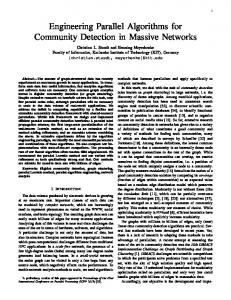
parallel encoding and decoding algorithms for Blob code. .... 4. a) Transformation of a tree into a regular binary tree (dummy nodes are marked in grey); b) ...
Parallel Algorithms for Encoding and Decoding Blob Code Saverio Caminiti and Rossella Petreschi Computer Science Department, Sapienza University of Rome Via Salaria, 113 - I00198 Rome, Italy {caminiti,petreschi}@di.uniroma1.it
Abstract. A bijective code is a method for associating labeled n-trees to (n − 2)-strings of node labels in such a way that different trees yield different strings and vice versa. For all known bijective codes, optimal sequential encoding and decoding algorithms are presented in literature, while parallel algorithms are investigated only for some of these codes. In this paper we focus our attention on the Blob code: a code particularly considered in the field of Genetic Algorithms. To the best of our knowledge, here we present the first parallel encoding and decoding algorithms for this code. The encoding algorithm implementation is optimal on an EREW PRAM, while the decoding algorithm requires O(log n) time and O(n) processors on CREW PRAM.
1
Introduction
A labeled n-tree is an unrooted tree on n nodes, each of which has a distinct label selected in the set [0, n − 1]. An interesting data structure for representing these trees can be obtained by encoding them by means of strings of node labels. This data structure is useful in many practical applications: Genetic Algorithms [20, 28], random uniformly distributed trees generation [10], fault dictionary storage [1], and distributed spanning tree maintenance [14]. The na¨ıve method to obtain a string C representing a labeled n-tree T , regarded as rooted in a fixed node (e.g., node 0), consists in associating each node x with its parent p(x): C is a string over the alphabet [0, n − 1] whose i-th element is p(i). C has cardinality n − 1 since the root has no parent and can be omitted. It should be noted that an arbitrary string of length n − 1 over the alphabet [0, n − 1] does not necessarily correspond to a tree (it may represents a graph which has cycles or is not connected). Here we are interested in those codes that define a bijection between the set of labeled n-trees and the set of strings over [0, n − 1]. Since Cayley proved that the number of labeled trees on n ≥ 2 nodes is nn−2 [8], we know that this kind of one-to-one mapping requires the length of the string to be equal to n − 2. In his proof of Cayley’s theorem, Pr¨ ufer presented the first bijective string based code for trees [27]. The Pr¨ ufer code proceeds recursively, deleting, at each step, the leaf with smallest label from the tree; whenever a leaf is deleted, the label of its parent is added to the codeword. Over the years since then, many codes behaving like the Pr¨ ufer one,
i.e., recursively eliminating leaves according to some rules, have been introduced by Neville [22], Moon [21], and Deo and Micikeviˇcius [11]. Other codes, based on ideas completely different from the recursive leaves elimination, have been presented along the years. Namely, the ϑn bijection by E˘gecio˘glu and Remmel [12]; the code due to Kreweras–Moszkowski [19]; the Chen code [9]; the Blob code, the Happy code, and the Dandelion code due to Picciotto [26]; and the MHappy code due to Caminiti and Petreschi [6]. In the last years, almost all these codes have been reinterpreted in a unified framework where their behavior is described as a transformation of the tree into a functional digraph [6]. This reinterpretation allowed researchers to highlight strong similarities among a set of codes, now called Dandelion-like codes [24] (the romantic name comes from the Dandelion code that transforms a tree into a graph similar to a dandelion flower). Encoding and decoding in sequential linear time is possible for all bijective codes presented in this introduction (see [5] for Pr¨ ufer-like codes, see [6] for Dandelion-like codes and [4] for a survey). Concerning parallel algorithms, studies have been performed and algorithms are known both for Pr¨ ufer-like codes [5] and for Dandelion-like codes [7]. The interested reader may found a complete survey on all these codes in [3]. In this paper we focus our attention on the Blob code introduced by Picciotto in her PhD thesis [26]. This code is based on the Orlin’s proof of Cayley’s theorem and makes explicit a bijection implicitly presented in that proof [23]. In its original description, the Blob code considers all nodes in decreasing label order, detaches them from their parents and adds them to a macro node called blob. During this process a string is generated (further details are given in Section 3). Both the original encoding and decoding algorithms require O(n2 ) time. By reinterpreting this code as transformation of the tree into a functional digraph, Caminiti and Petreschi [6] designed linear time encoding and decoding sequential algorithms. This reinterpretation also allowed Paulden and Smith to recognize that the Blob code is indeed equivalent to the Kreweras–Moszkowski code [24]. Moreover, several experimental analyses have been performed in the field of Genetic Algorithms to test Blob code performances focusing on certain desirable properties (namely locality and heritability) [17, 18]. Also theoretical investigations of the Blob code properties have been made [25]. For the best of our knowledge, here we present the first encoding and decoding parallel algorithms for the Blob code. The encoding algorithm can be parallelized on an EREW PRAM to run in O(log n) time with O(n/ log n) processors: the overall cost is linear and the algorithm is optimal. The decoding algorithm costs O(n log n) on a CREW PRAM since it runs in O(log n) time with O(n) processors. Our algorithms exhibit asymptotic behavior similar to that of parallel algorithms known in the literature for other bijective codes (see Table 1). It remains an open problem to decrease the cost of a decoding algorithm in order to reach the optimality. The paper is organized as follows: after a few preliminary definition, in Section 3, we recall the Blob code both in its original formulation and as reinter2
Encoding Pr¨ ufer
Decoding
O(n) EREW O(n log n) √ √ 2nd Neville O(n log n) EREW O(n log n) Pr¨ ufer-like √ 3rd Neville O(n) EREW O(n log n) √ √ Stack-Queue O(n log n) EREW O(n log n) Dandelion O(n) EREW O(n log n) ϑ bijection O(n) EREW O(n log n) n Dandelion-like Happy O(n) EREW O(n log n) MHappy O(n) EREW O(n log n)
EREW EREW EREW EREW CREW CREW CREW CREW
Table 1. Costs of known parallel algorithms for bijective codes. Costs are expressed as the number of processors multiplied by the maximum time required by a single processor working on a PRAM (EREW or CREW).
preted in [6]. Our main result is given in Section 4 where we present the first parallel encoding and decoding algorithms for Blob code.
2
Preliminaries
In this section, we introduce some definitions that will be useful in the rest of the paper. Definition 1. Given a function g : [0, n] → [0, n], the functional digraph G = (V, E) associated with g is a directed graph with V = {0, . . . , n} and E = {(v, g(v)) for each v ∈ V }. Lemma 1. A digraph G = (V, E) is a functional digraph if and only if the outer degree of each node is equal to 1. It is well known that each connected component of a functional digraph is composed of several trees, each of which is rooted in a node belonging to the core of the component, which is either a cycle or a loop (see Figure 1a). Functional digraphs are easily generalizable to represent functions undefined in some values: if g(x) is not defined, the node x in G does not have any outgoing edge. In this case, the connected component of G containing x is a tree rooted at x without cycles or loops (see Figure 1b). In this paper we only deal with labeled n-trees (simply trees), and each tree T will always be considered as rooted in the fixed node 0 with all edges oriented upwards from a node v to its parent p(v), i.e., T is the functional digraph associated with the function p. The notation PG (u, v) identify the set of nodes in the unique directed path in G between u and v (both excluded); when no ambiguity arises subscript G is omitted. As usual in mathematics, we use square brackets to include one or both 3
Fig. 1. a) A functional digraph associated with a fully defined function; b) A functional digraph associated with a function undefined in 0, 8, and 9.
endpoints. As an example, P (3, 6] represents the set {0, 2, 6, 8} in the digraph of Figure 1a. Let us call n-string a string of n elements over the alphabet [0, n + 1]. Definition 2. A code is a method for associating trees to strings in such a way that different trees yield different strings. A bijective code is a code associating n-trees to (n − 2)-strings.
3
Blob Code
In this section, we recall the Blob code as described by Piccitto in [26] and then we reinterpret this code in terms of transformation of a tree into a functional digraph as done in [6]. Given an n-tree rooted in 0, the encoding algorithm for the Blob code considers all nodes but 0 in decreasing label order. Each node is detached from its parent and added to a macro node called blob. This macro node has a parent in the tree (a normal node) but it contains many other nodes; each node included in the blob preserves its own subtree, if any, even though this subtree is not necessarily included in the blob. Some nodes force the blob to change its parent, others do not. The formers add the parent of blob to the codeword, while the others simply add their own parents. Formally the encoding algorithm can be described as follows and an example of its execution is given in Figure 2. Algorithm: Blob Encoding Input: a n-tree T rooted in 0 with edges oriented upward Output: an (n − 2)-string C 1. Initialize C as an empty vector indexed form 1 to n − 1 2. blob = {n − 1} 3. add edge (blob, p(n − 1)) and delete edge (n − 1, p(n − 1)) 4
Fig. 2. a) A sample tree T rooted in 0; b) An intermediate step of the execution of the Blob Encoding algorithm. The grey area identifies the blob, question marks in the code correspond to unassigned values; c) The resulting blob (and the codeword) at the end of the execution. 4. for v = n − 2 to 1 do if (P (v, 0) ∩ blob) 6= ∅) then 5. 6. C[v] = p(v) 7. delete edge (v, p(v)) 8. insert v in blob 9. else 10. C[v] = p(blob) 11. delete edge (blob, p(blob)) and add edge (blob, p(v)) 12. delete (v, p(v)) 13. insert v in blob
Let us now reinterpret the Blob code as done in [6]. For the sake of clearness, we explicitly report some lemmas (and proofs) in order to better clarify concepts that will be useful in Section 4. We will call stable (unstable) all nodes that affirmatively (negatively) satisfy the test of Line 5. Each stable node v let the blob parent unchanged and its value in the codeword C is simply p(v). Moreover, it is possible to see that the condition in Line 5 is not strictly connected with the incremental construction of the blob, but it can be computed a priori as the following lemma asserts: Lemma 2. Stable nodes are all nodes v such that v < max(P (v, 0)). Proof. When node v is considered by the Blob Encoding algorithm set blob contains all the nodes from v + 1 to n. Then the condition of Line 5 holds if and only if at least a node greater than v occurs in P (v, 0). u t As a consequence of Lemma 2, we are able to characterize the value written in the codeword by each unstable node: Lemma 3. In the codeword, the value corresponding to each unstable node v is p(z), where z is the smallest unstable node greater than v. 5
Fig. 3. a) A sample tree T rooted in 0; b) Stable nodes of T marked in grey; c) G = ϕb (T ) and the Blob code representing T .
Proof. In Line 10 of Blob Encoding algorithm the current parent of blob defines the code value corresponding to an unstable node v. In subsequent lines the blob becomes child of p(v). It implies p(blob) equal to the parent of the smallest unstable node greater than v, i.e., p(z). u t Lemma 3 allows us to define a function ϕb that constructs a functional digraph G from a tree T in the following way: for each unstable node v > 0, remove the edge (v, p(v)) and add the edge (v, p(z)), where z = min{u | u > v and u is unstable}. If z does not exist (it must be v = n − 1), edge (n − 1, 0) is added. In Figure 3a and 3c a tree T and its corresponding graph G = ϕb (T ) are depicted. Figure 3b shows all stable nodes of T . Lemmas 2 and 3 guarantee that the codeword computed by Blob Encoding Algorithm is equal to the string C = [g(1), g(2), . . . , g(n − 2)], where g is the function associated with the functional digraph G = ϕb (T ). Let us now describe how it is possible to reconstruct the original tree T starting from its codeword C, i.e., the decoding algorithm. Obtaining G from C is straightforward, indeed g(0) is always undefined and g(n − 1) is always 0. Thus, we will focus on proving that ϕb is invertible so that the tree can be obtained as T = ϕ−1 b (G). We need the following lemma: Lemma 4. Each path in T from a stable node v to m = max(P (v, 0)) is preserved in G = ϕb (T ). Proof. Let v be a stable node and let assume by contradiction that the path from v to m = max(P (v, 0)) is in T but not in G = ϕb (T ). This means that in the transformation from T to G at least one node w in P (v, m) has changed its parent. Since ϕb changes only edges outgoing from unstable nodes, w should be unstable and then w > max(P (w, 0)). w ∈ P (v, m) implies m ∈ P (w, 0), then w should be greater than m contradicting m = max(P (v, 0)). u t In order to invert the transformation operated by ϕb , all cycles in G have to be broken, and stable and unstable nodes have to be recomputed. Each cycle Γ 6
(loops as regarded as cycles of length 1) is broken deleting the edge outgoing from γ, the maximum node in Γ . Lemma 4 implies that γ is unstable in T , otherwise a node greater than γ would appear in Γ . Notice that γ becomes the root of its own connected component, while 0 is the root of the only connected component not containing cycles. We call stable in G each node v such that v < max(P (v, γv ]), where γv is the root of the connected component containing v. Lemma 4 guarantees that if a node is stable in T it is also stable in G. As proved in [6] vice versa is also true. Once stable nodes have been identified, the original tree T can be easily recomputed inverting the changes operated during the encoding. The computational complexity of the original Blob Encoding algorithm is quadratic in the number of nodes of the tree, due to the test in Line 5; the original decoding algorithm (not reported in this paper) is also quadratic. Our characterization of stable nodes (Lemma 2) decreases the complexity of the Blob Encoding algorithm to O(n). Linear complexity for both encoding and decoding algorithms can be achieved exploiting the transformation of the tree into a functional digraph. Indeed both ϕb and ϕ−1 can be implemented in b O(n) sequential time: the computation of maximum nodes in the upper path (coding) and the cycles identification (decoding) can both be implemented by simple search techniques [6].
4
Parallel Algorithms
Following the ideas introduced in the previous section, here we present parallel encoding and decoding algorithms for the Blob code. 4.1
Model of Computation
A wide range of parallel machines have been constructed in the past few years for executing instructions in parallel. Parallel processors may communicate either via shared memory or via fixed connections, in synchronous or asynchronous ways. The machine may be SIMD (all the processors execute the same instructions at the same time) or MIMD (the processors may execute different instructions simultaneously). It is possible to have concurrent or exclusive reading and writing operations. Consequently, each time a parallel algorithm is designed, it is necessary to specify the underling parallel machine. In this presentation we choose not to address a specific parallel architecture, but we describe our algorithms referring to the classical synchronous SIMD, shared memory, Exclusive Write PRAM model. Even though many researchers consider this model too abstract, we are convinced that PRAM is a robust theoretical framework suitable to describe high level parallel algorithms. Our choice is supported by the fact that this model is well studied both from a theoretical and a from practical point of view. Indeed, a great effort in designing a general purpose computer architecture to implement PRAM algorithms has been made in the last years, within the project PRAM-On-Chip at the University 7
Fig. 4. a) Transformation of a tree into a regular binary tree (dummy nodes are marked in grey); b) Nodes involved in Rake and Unrake operations.
of Maryland (see [31]). Moreover, a SIMD multi-thread extension of C language for providing an easy programming tool to implement PRAM algorithms has been developed. The results obtained so far seem to confirm the simplicity and the efficiency of the PRAM model. For more information we refer to [30]. Due to the lack of space, we cannot detail the basic parallel techniques used in this section (Prefix sum, Pointer Jumping and Parallel Tree Contraction), so we refer the reader to the classical book by J´aj´a [16]. Here we only recall Brent’s theorem: Brent’s scheduling theorem [2]: let n ∈ N represent the input size and p(n) be a processor bound function. Let A be an EREW PRAM algorithm that requires w(n) computational operations and t(n) time. If each of the p(n) processors can determine in time O(t(n)) which steps of A it needs to simulate, then parallel algorithm A can be simulated using O(w(n)/p(n) + t(n)) time and p(n) processors on an EREW PRAM. In the following costs are expressed as the number of processors multiplied by the maximum time required by a single processor. 4.2
Encoding Algorithm
Given a tree T , the first step in implementing the encoding phase, according with the discussion in Section 3, consists in identifying all stable nodes. To this purpose we compute, for each node v, the maximum value in the ascending path from v to 0: we call this information µ(v). Stable nodes are those nodes v such that v < µ(v) (see Lemma 2). In order to efficiently perform µ computation we use the Rake operation to obtain Parallel Tree Contraction and Decontraction. Initially T is transformed into a regular binary tree TR , i.e., a tree such that each internal node has exactly 2 children: for each node v ∈ T with d ≥ 1 children u1 , u2 , . . . , ud , TR has d + 1 nodes v1 , v2 , . . . , vd+1 where v1 corresponds to v while the other nodes are new dummy nodes. Each vi has vi+1 as right child and ui as left child. Figure 4a show an example of this transformation. During this process at most O(n) dummy nodes are introduced, thus the size of the tree does not asymptotically change. Dummy nodes are labeled with values that do not affect the computation of µ (e.g., negative values). Since TR is a regular binary tree the Parallel Tree Contraction can be performed using 8
exclusively Rake operations. For the sake of clearness, from now on we will call TC the tree that undergoes contraction even though the algorithm does not actually need to maintain two copies of the regular binary tree. Initially TC = TR and each node v set µ(v) equal to p(v) in TC (for the root node we set µ(0) = 0). When a Rake operation is performed to remove a node v and its leaf child f (see Figure 4b), the value of the other child u is updated as µ(u) = max(µ(u), µ(v)). As a consequence of this update, the following invariant is preserved at each step of the contraction process: (1) For each node v in TC it holds µ(u) = max(PTR (u, x]). Notice that the path from u to x is considered with respect to the uncontracted tree TR . Once the contraction is done and the tree is reduced to exactly 3 nodes (the root 0 and two leaves) the decontraction phase begins. All nodes removed during rake operations are reinserted backward into the tree by means of Unrake operations. When an Unrake operation is performed to reinsert node v and its leaf child f in between nodes x and u (see Figure 4b), the following updates are performed: µ(v) = max(µ(v), µ(x)) and µ(f ) = max(µ(f ), µ(v)). So, along the uncontraction process the following invariant is preserved: (2) For each node v in TC it holds µ(v) = max(PTR (v, 0]). We underline that, at the beginning of the uncontraction process, Invariant (2) holds for all the 3 nodes as a consequence of Invariant (1). To see that Invariant (2) holds for each other node v, let’s consider that, when v is reinserted by an Unrake operation, the following facts hold: by Invariant (1), value µ(v), computed during the contraction phase, is equal to max(PTR (u, x]); by Invariant (2), µ(x) = max(PTR (x, 0]); then the new value µ(v) = max(µ(v), µ(x)) = max(PTR (v, 0]). A similar argument holds for node f reinserted together with v by the Unrake. Once µ(v) is known for each node v ∈ T , a vector U containing all unstable nodes in increasing order can be computed. In order to avoid expensive sorting algorithms we enumerate unstable nodes by means of Prefix Sum [13] computation. Finally, in order to obtain the functional digraph G = ϕb (T ), we simply replace the parent of the i-th unstable node in U with the parent of the (i+1)-th unstable node in parallel. Notice that the last element in U is always node n − 1, and node 0 appears in U (even though we don’t use it). Algorithm: Blob Parallel Encoding Input: a n-tree T rooted in 0 represented by its parent vector p Output: an (n − 2)-string C indexed from 1 to n − 1 1. Compute µ(v) for each v ∈ T Create U containing all unstable nodes in increasing order 2. for v = 0 to n − 1 in parallel do 3. if v ≥ µ(v) then A[v] = 1 else A[v] = 0 4. Execute Prefix Sum on A 5. for v = 0 to n − 1 in parallel do 6. if v ≥ µ(v) then U [A[v]] = v 9
Exchange parents 7. for v = 1 to |U | − 2 in parallel do 8. p[U [v]] = p[U [v + 1]]
Generate the codeword 9. for v = 1 to n − 2 in parallel do 10. C[v] = p[v]
The computational complexity of this algorithm is optimal, indeed, Parallel Tree contraction can be implemented in O(log n) time with O(n/ log n) processors on an EREW PRAM (for a detailed description see [29]). Details on efficient transformation of a tree into a regular binary tree can be found in [15]. The same bounds hold for Prefix Sum computation. The four parallel cycles appearing in the algorithm require O(1) time with n processors and do not imply concurrent reading or writing. Applying Brent’s theorem all these operations can be scheduled on O(n/ log n) processors in O(log n) time. The overall cost is linear and thus the algorithm is optimal. 4.3
Decoding Algorithm
Let us now focus on the decoding phase. Graph G can be easily obtained from the codeword, then the most demanding step is the identification of stable and unstable nodes. We recall that a node v is stable in G if and only if v < max(P (v, γv ]), where γv is the maximum node in the core of the connected component containing v. In other words we have to compute the maximum value in the ascending path of each node v, let us call this value η(v). Differently from the encoding phase, here we cannot use Parallel Tree Contraction since the graph is not a tree: the ascending path of a node leads to the core of its connected component that may be a cycle or a loop. This computation can be obtained in a Pointer Jumping like fashion: for each node v we follow the outgoing edge (v, g[v]) searching for the maximum value in the ascending path. After each step we set g[v] = g[g[v]] and we stop after dlog ne steps to avoid infinite recursion inside cycles. The procedure details are as follows: Algorithm: Compute η Input: a functional digraph G represented by g Output: η(v) for each node v 1. g[0] = 0 2. for v = 0 to n − 1 in parallel do 3. η(v) = 0 4. for step = 1 to dlog ne do 5. for v = 0 to n − 1 in parallel do η(v) = max(η(v), g[v], η(g[v])) 6. 7. g[v] = g[g[v]] Once η has been computed, a vector U containing all unstable nodes in increasing order can be generated as done in the Blob Parallel Encoding 10
algorithm. The last step consists in inverting the parent exchanges performed in the encoding. Algorithm: Blob Parallel Decoding Input: an (n − 2)-string C indexed from 1 to n − 1 Output: a n-tree T represented by its parent vector p 1. p[0] = g[0] = undefined 2. for v = 1 to n − 2 in parallel do 3. p[v] = g[v] = C[v] 4. p[n − 1] = g[n − 1] = 0 5. Compute η(v) for each node v on vector g Create U containing all unstable nodes in increasing order 6. for v = 0 to n − 1 in parallel do 7. if v ≥ µ(v) then A[v] = 1 else A[v] = 0 8. Execute Prefix Sum on A 9. for v = 0 to n − 1 in parallel do 10. if v ≥ µ(v) then U [A[v]] = v Exchange parents backward 11. for v = 2 to |U | − 1 in parallel do 12. p[U [v]] = p[U [v − 1]] 13. p[U [1]] = 0 The more demanding step of Blob Parallel Decoding is the computation of η realized by algorithm Compute η. It requires O(log n) sequential iterations, each of which uses O(n) processors. Moreover, for this algorithm the concurrent read model is required, indeed, in Line 6, several nodes may access the same g[v] and η(g[v]) concurrently. Once η is known, the computation of vector U , as well as all the parallel cycles, can be implemented in O(log n) time with O(n/ log n) processors on a EREW PRAM. The overall cost of Blob Parallel Decoding is O(n log n) on a CREW PRAM.
References 1. V. Boppana, I. Hartanto, and W.K. Fuchs. Full Fault Dictionary Storage Based on Labeled Tree Encoding. In Proc. of IEEE VTS, pages 174–179, 1996. 2. R.P. Brent. The Parallel Evaluation of General Arithmetic Expressions. J. of ACM, 21(2):201–206, 1974. 3. S. Caminiti. On Coding Labeled Trees. PhD thesis, Sapienza University of Rome, December 2007. 4. S. Caminiti, N. Deo, and P. Micikeviˇcius. Linear-time Algorithms for Encoding Trees as Sequences of Node Labels. Congr. Num., 183:65–75, 2006. 5. S. Caminiti, I. Finocchi, and R. Petreschi. On Coding Labeled Trees. TCS, 382(2):97–108, 2007. 6. S. Caminiti and R. Petreschi. String Coding of Trees with Locality and Heritability. In Proc. of COCOON, LNCS 3595, pages 251–262, 2005.
11
7. S. Caminiti and R. Petreschi. Parallel Algorithms for Dandelion-Like Codes. In Proc. of ICCS, LNCS 5544, pages 611–620, 2009. 8. A. Cayley. A Theorem on Trees. Quart. J. of Math., 23:376–378, 1889. 9. W.Y.C. Chen. A General Bijective Algorithm for Trees. Proc. of NAS, 87:9635– 9639, 1990. 10. N. Deo, N. Kumar, and V. Kumar. Parallel Generation of Random Trees and Connected Graphs. Congr. Num., 130:7–18, 1998. 11. N. Deo and P. Micikeviˇcius. A New Encoding for Labeled Trees Employing a Stack and a Queue. Bull. of ICA, 34:77–85, 2002. ¨ E˘ gecio˘ glu and J.B. Remmel. Bijections for Cayley Trees, Spanning Trees, and 12. O. Their q-Analogues. J. of Comb. Th., 42A(1):15–30, 1986. 13. M.J. Fischer and R.E. Ladner. Parallel Prefix Computation. J. of ACM, 27(4):831– 838, 1980. 14. V.K. Garg and A. Agarwal. Distributed Maintenance of a Spanning Tree Using Labeled Tree Encoding. In Proc. Euro-Par, pages 606–616, 2005. 15. R. Greenlaw and R. Petreschi. Computing Pr¨ ufer Codes Efficiently in Parallel. DAM, 102(3):205–222, 2000. 16. J. J´ aj´ a. An Introduction to Parallel Algorithms. Addison-Wesley, 1992. 17. B.A. Julstrom. The Blob Code: A Better String Coding of Spanning Trees for Evolutionary Search. In Proc. of ROPNET, pages 256–261, 2001. 18. B.A. Julstrom. The Blob Code is Competitive with Edge-Sets in Genetic Algorithms for the Minimum Routing Cost Spanning Tree Problem. In Proc. of GECCO, pages 585–590, 2005. 19. G. Kreweras and P. Moszkowski. Tree Codes that Preserve Increases and Degree Sequences. J. of Disc. Math., 87(3):291–296, 1991. 20. M. Mitchell. An Introduction to Genetic Algorithms. MIT Press, 1996. 21. J.W. Moon. Counting Labeled Trees. William Clowes and Sons, London, 1970. 22. E.H. Neville. The Codifying of Tree-Structure. Proc. of Cambridge Phil. Soc., 49:381–385, 1953. 23. J.B. Orlin. Line-Digraphs, Arborescences, and Theorems of Tutte and Knuth. J. of Comb. Th., 25:187–198, 1978. 24. T. Paulden and D.K. Smith. Recent Advances in the Study of the Dandelion Code, Happy Code, and Blob Code Spanning Tree Representations. In Proc. of CEC, pages 2111–2118, 2006. 25. T. Paulden and D.K. Smith. Some Novel Locality Results for the Blob Code Spanning Tree Representation. In Proc. of GECCO, pages 1320–1327, 2007. 26. S. Picciotto. How to Encode a Tree. PhD thesis, University of California, San Diego, 1999. 27. H. Pr¨ ufer. Neuer Beweis eines Satzes u ¨ ber Permutationen. Archiv der Mathematik und Physik, 27:142–144, 1918. 28. C.R. Reeves and J.E. Rowe. Genetic Algorithms: A Guide to GA Theory. Springer, 2003. 29. J.H. Reif. Synthesis of Parallel Algorithms. Morgan Kaufmann, 1993. 30. U. Vishkin, G.C. Caragea, and B. Lee. Models for Advancing PRAM and other Algorithms into Parallel Programs for a PRAM-On-Chip Platform. In Handbook of Parallel Computing: Models, Algorithms and Applications, chapter 5. CRC Press, 2008. 31. X. Wen and U. Vishkin. PRAM-on-Chip: First Commitment to Silicon. In Proc. of SPAA, pages 301–302, 2007.
12