The fourth and last stage of this development is marked by the appearance of the ..... Howell and Mark Lane of CREWES are thanked for technical assistance.
Parallel Computation
In Seismic Modelinq
Parallel computation in seismic modeling" Lawrence H. T. Le, Ernest R. Kanasewich 1,Flavian Abramovici 2, E. S. Krebes and Wayne Karpoff 3 ABSTRACT
Three algorithms of seismic forward modeling in layered structure are implemented on a Myrias parallel computer SPS-2 with 64 processors. The effort in porting the codes to the parallel machine is minimal. Computational efficiency rating of more than 90% is achieved in all three cases. INTRODUCTION
Everybody trying to understand the structure of the earth as revealed by natural or man-made earthquakes, knows that major progress implied always advances in three main directions: theoretical studies based on classical and modern mathematics, reliable field instrumentation for recording the earth movements and computing devices, making possible both to use theoretical results in a practical way and to process the seismic data. During almost a century of development, every essential improvement in one direction had a significant impact on the others, giving a new perspective and motivation. Of course this interplay was stronger between the theoretical side and the development of the recording systems. However, the way the theory was choosing its topics and how the data was handled were influenced directly by the computing power at hand or the one deemed to appear in the near future. As long as the computing power was restricted to mechanical or electrical desk calculators or to very primitive devices driven by punched cards, the main stress in the theoretical work was on very simple earth models and relatively simple approximations, leading to a not very complicated set of final expressions used in the calculations. The picture changed however when the modem computers appeared on the scene in the fifties and improved in the sixties, and new ways to write programs in new computer languages, like FORTRAN or ALGOL appeared. The theoreticians were led now to study complex models for which, besides the results based on the classical mathematical physics methods, new results based on purely numerical methods like finite differences were obtained. Simultaneously, the people creating or improving the recording instruments and handling the data were able to set up networks on large areas for either one-time experiments or for extended-time recordings. As a gross picture of the development of modem seismology in this century, we thus distinguish four major stages.
* first d,-_L 1Instituteof EarthandPlanetarySciences,Departmentof Physics,theUniversityof Alberta, Edmonton, Alberta, Canada T6G 2J1 2 Schoolof MathematicalSciences,Raymondand BeverlySacklerFacultyof ExactSciences,Tel Aviv University, Tel Aviv, Israel. 3 MyNas Computer Technologies Inc., 8522 Davis Rd, Edmonton, Alberta T6E 4Y5.
CREWESResearchReport Volume4 (1992)
28-1
I_e,Kanasewich,Abramovici,Krebes,and Karpoff The first stage includes the first four decades and was characterized by solid beginnings mainly in the theoretical approach and instrumentation. Then, after a relatively short recess due to the second world war, came a new stage based on the appearance of modem computers and serious advances in electronics, combined with major advances in some theoretical fields like information theory. This stage had two periods, one of a slower pace during the fifties and one of rapid progress in the sixties. Then came the third stage, when the now "classical" computers reached new heights as far as computation speed and memory capacity and access were concerned. On the other hand, people gathering field data had much better instruments and networks of such instruments and also improved ways to make use of the accumulated data. However, perhaps the most important progress in this period was made on the theoretical front as now people managed to reformulate already known problems and solutions using modem mathematical tools like the modem matrix theory or new techniques from the theory of linear operators. Moreover, new theories were created, enabling the most efficient use of the accumulated data, like the Backus-Gilbert linear inversion and migration. The fourth and last stage of this development is marked by the appearance of the supercomputers of the eighties, the vector and the parallel computers, promising to speed up the number crunching operations tremendously, making thus possible to handle problems that were considered previously beyond reach. To take advantage of this huge potential, programs written for "classical" machines have to be converted to the new ones, which brings into focus the question of efficiency related not only to the price/performance of the computer itself, but the price/performance of the entire process of solving a certain problem by the user, including moving to a new system, a new compiler, working sometimes through a front-end machine and considering the fact that not the whole problem is "vectorizable" or "parallelizable". It seems that there is no universal answer to the question which machine or which type of machine is best, but for each problem and, perhaps, each major component of a problem, one type of machine may be better suited than another. This is why it is very important to experiment with such systems and make the conclusions available to others. In the present paper, we describe three examples of theoretical studies, the corresponding solutions of which have been computed numerically on a Myrias parallel computer: (A) a wave modeling problem on the Fourier-Bessel displacements of an elastic or viscoelastic structure,
representation
of the
(B) a problem of wave propagation through a finely layered material having a very large number of layers, solved by matrix products involving the reflection and transmission coefficients, and (C) the computation of synthetic seismograms using a stationary ray technique for an anelastic media. As we shall show, the modification of the computer programs from the versions running on work stations was very slight and easy to implement. On the other hand, the efficiency of the machine was very high.
28-2
CREWESResearchReport Volume4 (1992)
ParallelComputationIn SeismicModelinq THE MYRIAS
COMPUTER
SYSTEM
Myrias produces medium-grained MIMD parallel computers. Central to the Myrias system is a high investment in software and an easy to use programming paradigm. The approach is to provide a simple method of expressing explicit parallelism at the applications level and then using compiler and operating system technology to provide automatic task distribution, load balancing, memory distribution, paging and merging. The programmer expresses parallelism by changing FORTRAN DO loops (ANSI C is also supported) into PARDO, either directly or with compiler directives. Each iteration through the loop creates a separate execution stream, called a child task, which, therefore, must not depend on the results of previous loop iterations. These tasks are executed in parallel by dynamically distributing them across idle processors. The inside of the PARDO loop can be arbitrarily complicated. PARDOs can be nested. The task can call subroutines which may also include PARDOs. PARDOs may be recursively nested. Because of automatic load balancing, all tasks do not have to possess the same computational length. A key to the paradigm is the memory semantics. Conceptually, when a PARDO is encountered each newly created child task obtains its own complete copy of all variables (the address space). The tasks execute independently with their own copies of the variables until the completion of the iteration. The individual address spaces are then "merged" according to four separate merging rules which can be selected on a variable by variable, PARDO by PARDO basis with a compiler directive: (a) Default Merging: if all children only read a value, or do not refer to it, then the value after merging will be the same as before the PARDO. If one child stores a value into a variable or several children store the same value into a variable, then that value will be the result of the merging. A variable will be "undefined" at the end of merging if several children store different values into the variable. This is to ensure the deterministic behavior of the paradigm and allow Myrias debugger technology to assist in locating the use of undefined values resulting from colliding stores. (b) Accumulation Merging: Variable copies can be added together according to several arithmetic operations. For example, summation merging [mergeby (sum) X] makes programs of the form X=X+f(...)
(1)
work in parallel (i.e., each iteration of the loop adds something to the result of the other iterations). (c) Selection Merging: The maximum (or minimum) value from the results of the individual tasks are chosen. It is also possible to have another variable copied from the task which was selected (maximum and copy, minimum and copy). (d) Null Merging: Throw the results away. This is useful for large temporary arrays. The actual implementation of the above allows for maximum efficiency. Memory is "copied" on as needed basis. "Merging" is done in parallel and as a
CREWESResearchRel_ort Volume4 (1992)
28-3
Le, Kanasewich,Abramovici,Krebes,and Karpoff background activity. Tasks do not block (i.e. stop and wait for a variable to be copied or merged) until absolutely necessary. Transparent demand paging between processors is used to extend the available memory to individual processors. Although not used in this research project, several other features are present in the paradigm. The PARBEGIN/PARALLEL construct allows for parallelizing independent blocks of code not contained in a DO loop. Branching outside of a PARDO loop (or executing a break statement in C), allows for speculative parallelism. A construct is available to optimize finer grained loops. Lower levels of parallel control are available through Global Shared Memory, where every task sees the same copy of a page and it is moved between tasks when referenced. A message passing interface is also available for experienced programmers porting from other parallel systems. In a geophysics context, there appear to be several advantages to the above approach. First, it is clearly easy to use. In our experience, a few compiler directives inserted into a seismic application will obtain a high parallel efficiency. Second, automatic scaling of seismic applications to a very large number of processors has been demonstrated (Kapotas, 1991). Third, future Myrias hardware platforms will not require additional porting effort. This code was developed on an older Myrias model, the SPS-2, and then run on a SPS-3 after simply recompiling. Fourth, because memory motion is dynamic and implicit, it is possible to parallelize algorithms in which determining a suitable memory partitioning at compile time is difficult or impractical due to input data dependencies. Fifth, the automatic load balancing and dynamic memory management should make it easier to port production codes with special cases which cause tasks with different behavior. The bulk of this research was done on the 64 processors (soon to be upgraded to a 320 processor) SPS-2 at the University of Calgary. The Myrias SPS-2 is a hierarchically connected, distributed memory system, i.e., a system with individual processing elements (PEs), each with their own memory, interconnected in a hierarchical fashion with high speed interprocessor busses. The SPS-2 PE has a Motorola 68020, a 68882 floating point coprocessor, and 4 megabytes of memory. The Myrias's new platform, the SPS-3, which uses a Motorola 68040 CPU with 8 or 16 Megabytes of real memory. Both the SPS-2 and the SPS-3 can have between 4 and 4096 PEs in a system. In both computers, four PEs share a common card bus. A cage houses sixteen cards (or 64 PEs) which share two backplane busses (four for the SPS3). Multiple cages are interconnected using five intercage ports which can be daisy chained. All of the above busses operate at 33 Megabytes per second transfer rate, except for the SPS-2 intercage links which run at 11 Megabytes per second. SEISMIC
(A) Full Wave Structure
Modeling
FORWARD
in Vertically
MODELING
Inhomogeneous
and Viscoelastic
We consider the free surface response of an inhomogeneous, isotropic and anelastic layer of thickness z = H overlying a homogeneous and isotropic half-space to an activation of a buried explosion. Each sublayer of the layered half-space is characterized by the elastic velocities, tx and ,6, density, p and quality factors, Qa and Q/_. Within each sublayer, the velocities and density do not change laterally but may ctiange continuously with depth.
28-4
CREWESResearchRel_ort Volume4 (1992)
ParallelComputationIn SeismicModelinq The displacement components at the free surface, z = H can be expressed as (Abramovici, Le and Kanasewich, 1991; Le, Abramovici and Kanasewich, 1991):
Sz =
Vo _e 2]r2
G((9) e ion,d(9
Jo(kr) "So((9,k,zs) dk
(2)
Vo 9_e 2iv2
G((9)eiC°td(9
Jl(kr)S'l((9,k,zs)dk
(3)
and
st-
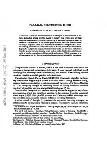
where Sz and sr are the vertical and radial displacements respectively, (9 is the angular frequency, k, the horizontal wavenumber, Jo and J1, the ordinary Bessel function of order zero and one, Vo, the volume generated at the source in one second, G((9), the Fourier transform of the time-dependence of the source, g(t) being equal to zero for t -< 0 and 9_e stands for real part of a quantity. The reflectivity functions "Sn((9,k,zs) for n = 0, 1 account for the transmission and reflection effects within an inhomogeneous layer. The computation of either (2) or (3) is achieved by integrating tin'stthe k-integral and then inverting the spectral result after being modified by the source function into the time domain by means of an inverse fast Fourier transform. For every model and source location, the main computational effort is to evaluate the reflectivity functions. The procedure requires, for every (9, the integration of systems of complex equations of orders four and six over a real independent variable, k. Complex systems are dealt with since the medium is viscoelastic. In our approach, a large binary file of (9-k series is obtained. The series are later modified by the Bessel functions with arguments corresponding to a particular source-receiver offset configuration and then summed to give the spectral displacement response. The code originally written for Sun Sparc double precision is implemented on Myrias SPS-2 shown in Figure 1. The outputs are written in binary length, in the order corresponding to the processor writes the output to the n'th block.
station using FORTRAN 77 in with minimum modification as format to blocks of fixed record number, i.e., the n'th processor
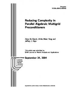
Figure 2 shows the synthetic velocity record of vertical component
for the
model in TABLE 1. A wavenumber taper { 0/0/¢J_e(o)/al)/_e(o)]_l) } was applied to exclude the Rayleigh wave arrival. A Gaussian time-variation (Abramovici, Le and Kanasewich, 1990) with a dominant frequency of 35 Hz was used and the cosine taper used was (0/0/125/140 Hz). The calculation took 13 min in SPS-2 using 64 processors for 512 frequency components. 95% computation efficiency is achieved while 92% rating is obtained with I/O included.
CREWESResearchReDort Volume4 (1992)
28-5
Le, Kanasewich,Abramovici,Krebes,andKarpoff PARDO 50 over frequency components DO 10 over wavenumber components compute thereflectivity
functions
10 continue output the results 50 continue
Figure 1. A schematic PARDO-loop.
TABLE 1 A shallow exploration model with an explosive point source buried 10 m below the free surface, tr is the Poisson's ratio.
p
Ot
¢r
Qa
Qfl
h
(g/era 3)
(km/s)
2.1
1.88
0.32
30
30
100
2.1
1.96
0.32
30
30
190
2.1
2.10
0.32
30
30
55
2.1
2.22
0.32
30
30
65
2.1
2.30
0.32
30
30
110
2.1
1.70
0.20
30
30
44
2.1
2.40
0.32
30
30
76
2.3
4.20
0.32
(B) Wave Propagation
Through
(km)
1000
Finely Layered
1000
Medium
Here, we want to compute the SH-transmitted response to a plane wave incident on a stack of homogenous isotropic layers bounded by two half-spaces. The receivers and the impact point are on the same vertical axis simulating a well-logging environment. The algorithm, which was briefly described by Chang (1987), calculates the spectrum response for a given range of frequencies up to a Nyquist frequency by computing recursively the global transmission coefficient, Tn for the entire structure: Tn=Tn+ l(l-Pn+
28-6
l Rn+l'n en+ l Rn+ l}-l pn+ l Tn'n+ l
CREWESResearchRePort Volume4 (1992)
(4)
Parallel Computation
In Seismic Modelinq
where I is the identity matrix and Rn is the global reflection coefficient : Rn=R_ n+l + Tn+ l,n pn+ l Rn+ l(l-Pn+
l Rn+l, n pn+ l Rn+ l)-l pn+l Tn, n+ l
(5) for n = N-I,...,1 where N is the number of layers. Ri, Jand Ti, Jare the normalized (by energy flux) reflection and transmission coefficients for a single interface and the vertical phase factor, Pn is P,, = exp ( i cohn r/n)
(6)
where
/_/-_n r/n=
- P2
i_-_-n2
f°r P ;2
hn is the layer thickness of the n'th layer, co the angular frequency, fl the shear wave velocity andp the slowness. The recursion starts at the bottom interface with the initial values: RN-1 =R N-I'N
and
TN_I
=T N-I'N
and work upward to the top layer. Fourier transform.
(8)
The time response is obtained by inverse fast
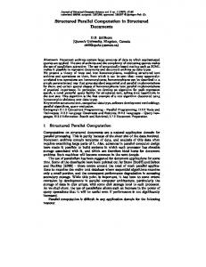
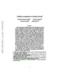
The model shown in Figure 3 consists of 1750 homogeneous isotropic layers bounded between two half-spaces. Velocities are randomly generated and uniformly distributed with means 50 I.ts/ft, 67 p.s/ft and 33 I.ts/ft respectively to make up three distinct zones. Constant density of 2.5 grn/cc is used for all layers. The thickness sequence is exponentially distributed with means 2 ft, 1 ft and 4 ft. The code was originally run in the Cray with two DO-loops. The outer DO-loop is over frequency components while the inner DO-loop is over the number of interfaces. In Myrias parallel computer, the outer DO-loop is done in parallel. At 5° angle of incidence, Figure 4 shows the broad pulse after the direct transmitted arrival for an incident plane wave which has traversed 400, 800, 1200 and 1600 layers respectively. The broad pulse is made up of multiply scattered energy (Burridge and Chang, 1989a & b; Richards and Menke, 1983) displaying apparent attenuation and dispersion. The computation took 45 sec in the Cray X-MPEA (Schlumberger-Doll Research Lab) and 442 sec in the Myrias with 64 processors for 4096 frequency components. The parallel machine achieves 97 % efficiency in computation with output and only 92 % including input. The later efficiency rating is obtained since at the beginning of the run, only one processor reads in the data file while 63 processors stay idle.
CREWESResearchReport Volume4 (1992)
28-7
Le, Kanasewich, Abramovici, Krebes, and Karpoff (C) Complex
Ray
Modeling
in Anelastic
Layered
Medium
In this section, we discuss the computation of ray-synthetic seismograms for a point source in a horizontally layered anelastic medium. The theory used to compute the traveltimcs and amplitudes of the rays is given by Hearn and Krebes (1990), and is briefly oudincd below. In this theory, the vertical component of particle displacement, Uz, at an observation point due to a primary compressional wave passing through a sequence of anelastic layers is given by
uz(t)= fl Y s (o))exp[i co(T-t)]bzdCO where
Y is the product
of the particle
(9) displacement
reflection
and transmission
coefficients, L is the geometrical spreading factor, S(o)) is the spectrum of the source of source waveform, T is the traveltime, and bz is the vertical component of the unit vector which
gives
the direction
of the compressional
wave particle
motion
at the
observation point. Y, L, T and b are functions of the ray parameter p and the layer velocities vj, and are identical in form to their counterparts in a perfectly elastic medium, except thatp and vj are complex and frequency-dependent. The complex traveltime T is given by m
r=px+ E hi4 v;2-p2 j=a
(10)
where X is the (real) horizontal distance between the endpoints of the raypath (the source and receiver points, say), and hj and vj are the layer thickness and complex velocity associated with the jth ray segment. The complex ray parameter p is determined by the requirement that the complex travehime be stationary, i.e., dT/dp = 0, which, from eq. (10), is m
X=
E
pvjhj(1-p2v2_
1,2 (11)
j=l
This equation can be solved for p using Newton-Raphson method, and we refer to the corresponding ray as a stationary ray. It is also a complex ray, in that the Cartesian coordinates of points on the raypath (except for the endpoints) are complex numbers (see Hearn and Krebes, 1990, for details). In other words, the wave travels through complex 3D space. This is not, of course, a physically real aspect of the wave propagation. It is merely a natural and convenient mathematical way of describing the wave motion. The medium model we use is given in Table 2. It is the same as the model used by Hearn and Krebes (1990). The velocities VH shown in the table are the speeds of
28-8
CREWES Research Report Volume 4 (1992)
Parallel Computation homogeneous homogeneous formula
In Seismic Modelinq
waves at a reference frequency of 10 Hz. At other frequencies, the wave speeds are computed from the well-known velocity dispersion
V.(o)) = Vn(_r) [ 1 + 1]rQ In (_ o_/j (-0/]
(12)
where oh-is the radial reference frequency, and the quality factor Q is assumed to be approximately independent of frequency. The complex velocity v is given in terms of VH and Q by
v2=V2[I+_/a+Q 2( 1 +Q_2)(1 -2 ]
+iQ-I)
(13)
(see Krebes, 1983). We use a source pulse with a zero-phase trapezoidal 5-10-50-60 Hz band-pass spectrum S(_o). The code is written in Fortran 77, and was originally written for a Sun computer, with output in single precision ASCII format. For a given source-receiver offset, the waveforms uz(t) of the primary arrivals are computed with an inverse FFT and summed to form the seismograms. In porting the code to the Myrias parallel computer, the DO loop over the offsets was done in parallel (with the PARDO statement), as the computations for each receiver location are the same. The output is written in single precision binary format. The results, shown in Figure 5, were run in SPS-2 using 50 parallel processors. The run achieved a 91% efficiency rating in computation time and took 39 seconds. The overall performance rating, including I/O, was 87%. TABLE 2 The medium model, with velocities at 10 Hz. The point source and the receivers are located in the upper half-space at a distance of 0.5 km above the first interface.
P
VHp
VHS
Qp
Qs
h
([_/cm 3)
(km/s)
(km/s)
2.0
1.8
0.8
40
20
oo
2.1
2.3
1.1
50
25
1.0
2.2
3.0
1.5
60
30
1.0
2.3
4.0
2.1
70
35
1.5
2.4
4.8
2.6
80
40
_,
(km)
CREWESResearchRel_ort Volume4 (1992)
28-9
Le, Kanasewich, Abrarnovici, Krebes, and Karpoff CONCLUDING
REMARKS
For the examples shown in this paper, transferring codes from work stations or scalar mainframes to parallel computers may improve dramatically program performance. The efficiency of the machines we used was very high due to fact that the computing elements work independently and simultaneously but also due to the ease by which our programs were converted. ACKNOWLEDGMENTS
This research was supported by the sponsors of the Consortium for Research in Elastic Wave Exploration Seismology (the CREWES project). The computational time was donated by the Myrias Technologies Inc. We would like to thank the CREWES director, Robert Stewart for encouragement. Brian Lake and Chris Gray of the Myrias Technology Inc., Doug Phillips, Brian Goodings and Kim Tran of ACS and Tina Howell and Mark Lane of CREWES are thanked for technical assistance. Discussion with Rod Wittig of the High Performance Computer group, ACS, the University of Calgary is very helpful. The Cray version of the SH code for finely layered medium was developed in Schlumberger-Doll research lab while L.L. visited there. L.L. wishes to thank Drs. R. Burridge (SDR) and H.W. Chang (SLCS) for fruitful discussion.
REFERENCES
Abramovici, F., Le, L. H. T. and Kanasewich, E.R., 1990, The solution of Cagniard's problem for a SH line source in elastic and anelastic media, calculated using a_-kintegrals: Bull. Seism. Soe. Am., 80, 1297-1310. Abramovici, F., Le, L.H.T. and Kanasewich, E,R,, 1992. Seismograms using w-k integrals for a point source in a vertically inhomogeneous anelastic model, submitted to Bull. Seis. Soc. Amer. Burridge, R. and Chang, H.W.. 1989a. Multimode, one-dimensional wave propagation in a highly discontinuous medium. Wave Motion, 11,231-249. Burridge, R. and Chang, H.W., 1989b. Pulse evolution in a multimode, one-dimensional, highly discontinuous medium, in Elastic wave propagation edited by M.F.McCarthy and M.A. Hayes, Elsevier, 229-234. Chang, H.W., 1987. 3-D reflection/transmission coefficients from cylindrical layered elastic media. Ultrasonics symposium, 455.459. Eisher, E., 1989. Supercomputers in seismic exploration. Pergamon Press. Hearn, D.J. and Krebes, E.S., 1990. On computing ray-synthetic seismograms for anelastic media using complex rays. Geophysics, 55, 422-432. Kapotas, S., 1991. Some seismic applications in Myrias. Ph.D. thesis, University of Alberta. Krebes, E.S., 1983. The viscoelastic reflection/transmission problem: two special cases. Bull. Seism. Soc. Am., 73, 1673-1683. Le, L.H.T., Abramovici, F. and Kanasewich, E.R., 1990. Synthetic seismograms for vertically inhomogeneous and anelastic media using spectral (og-k) method: 6oth Ann. Internat. Mtg., Soc. Expl. Geophys., Expanded Abstracts. Richards, P.G. and Menke, W., 1983. The apparent attenuation of a scattering medium. Bull. Seis. Soc. Amer., 73, 1005-1021.
28-10
CREWES Research Report Volume 4 (1992)
Parallel
Offset 0.05
0.05 _ _
Computation
In Seismic
Modelinq
(kin) 1.2
2.4
0
09
E Io--
2.0
Figure 2. Synthetic velocity seismograms of vertical component for the model in TABLE 1. No gain compensation was applied to the data.
CREWES Research Report
Volume 4 (1992)
28-11
Le, Kanasewich, Abramovici, Krebes, and Karpoff
4500 4000 35OO ..-&
"" 3000 ,M
2500 > >
2000 1500 I000 500 0
100
200
300
400
500
600
700
800
900
dcpth(m)
Figure 3. Randomly generated shear wave velocities for a finely layered medium consisting of 1750 layers bounded between two half-spaces.
28- 12
CREWES Research Reoort Volume 4 (1992)
1000
Parallel
Computation
In Seismic
Modeling
5 e.
-,
.s
"'.,
•
3
'"..... '".""""
'",,,
(3.21
-....
N = J600
.,.,,,,.,*,'"'"'",,"*,.-'""'**,.,,,,*"*"*'"',,..,,.,,,.,...,,,,,.,,
N = J200 "" "'.
"_
E=
',,
N = 800
¢0
•N = 400 0
-1 0
50
100
150
200
250
Time Index
Figure 4. The transmitted wavefield response for a plane wave incident at 5° angle and traveling through 400, 800, 1200 and 1600 layers respectively.
CREWES
Research
Report
Volume
4 (1992)
28-13
Le, Kanasewich, Abramovici, Krebes, and Karpoff
Trace Number TSN
tO
OoO
20
30
L IIIIllJIIil
40
50
TSN
I
0°0
0,5
0°5
1o0
toO
t O dO r_ to5
1o5
oO
E 2,o
a.o
+ 2,,5
2°5
3o0
3°0 I
3.5
Figure
5. Ray-synthetic
40 m with 40 m spacing.
28-14
3°5
seismograms Each
for the model
trace was scaled
in TABLE
with a function
CREWES Research Ref_ort
2. The closest proportional
Volume 4 (1992)
offset is
to t3,