Fraunhofer. Institut. Schicht- und. Oberflächentechnik. Domain decomposition in YZ plane. DSMC model of an in-line coater. ZP3 ZP2. ZP1. ZM. ZV1. ZV2. 425.
Euro-PVM/MPI 2006, Sept. 17-20, 2006
Parallel DSMC Gas flow Simulation of an In-line Coater for Reactive Sputtering
Andreas Pflug, Michael Siemers, Bernd Szyszka
Fraunhofer Institute for Surface Engineering and Thin Films IST Bonn, September 20, 2006
Pfl, Sie, Szy 2006-09-20
Fraunhofer Institut Schicht- und Oberflächentechnik
Euro-PVM/MPI 2006, Sept. 17-20, 2006
Outline 1.
Introduction
2.
Details of parallel DSMC implementation
3.
DSMC model of an in-line coater
4.
3D Gas flow simulation with moving glass substrates
5.
Conclusion Pfl, Sie, Szy 2006-09-20
Fraunhofer Institut Schicht- und Oberflächentechnik
Euro-PVM/MPI 2006, Sept. 17-20, 2006
Outline 1.
Introduction
2.
Details of parallel DSMC implementation
3.
DSMC model of an in-line coater
4.
3D Gas flow simulation with moving glass substrates
5.
Summary and outlook Pfl, Sie, Szy 2006-09-20
Fraunhofer Institut Schicht- und Oberflächentechnik
Introduction / Motivation
Reactive magnetron sputtering Sketch of an in-line sputtering compartment and a magnetron Magnetron
Compartment of an in-line sputtering coater
a) Cross section through a magnetron sputtertarget B
B
E
E N
to MF generator
S
E S
Vacuum
Vacuum
N
N
S
+/-
S
N
N
S
-/+
S
N
TargetMaterial Shielding
b) Erosion track on target surface
Gas inlet e. g. Ar, O2, ...
Shielding
Glass substrate Transport
Gas inlet e. g. Ar, O2, ...
system
Pfl, Sie, Szy 2006-09-20
Fraunhofer Institut Schicht- und Oberflächentechnik
Introduction / Motivation
Goals for simulation of reactive magnetron sputtering � Process stability
- Feedback control for non-stable transition mode - Coupling of magnetrons - Pumping speed, noise and latency times
� Homogeneity
- Lateral homogeneity: influence of substrate movement - Vertical homogeneity: magnetron drift current
� Productivity
- Fast access of operation conditions after maintenance or product change
Pfl, Sie, Szy 2006-09-20
Fraunhofer Institut Schicht- und Oberflächentechnik
Introduction / Motivation
Concept of DOGMA Dynamic, spatially resolved, coupled, macroscopic model Runge-Kutta integration (fast!)
Flow conductances
Surface chemistry
Monte Carlo simulation
Heuristic model of the plasma impedance
DSMC - Gas flow Monte Carlo simulation
Balance between surface and volume Berg‘s Model 1986 Surface metallization
Pressure distribution Time consuming MC calculations (initial step)
PIC-MC plasma Sputter particles
Fraunhofer Institut Schicht- und Oberflächentechnik
� A. Pflug et al.; Thin Solid Films 442 (2003) 21-6. Pfl, Sie, Szy 2006-09-20
Introduction / Motivation
Gas flow models Pressure regimes DSMC Method
Boltzmann transport equation without collision treatment
Boltzmann transport equation
FEM flow simulation Euler
Navier Stokes
Fluid limit
0
0.01
0.1
1.0
10
100
Typical process conditions
Limit of free particles
∞
Kn = λ/d (nach Bird 94)
� G. A. Bird, Molecular gas dynamics and the direct simulation of gas flows, Oxford Engineering Science Series 42 (1994) Pfl, Sie, Szy 2006-09-20
Fraunhofer Institut Schicht- und Oberflächentechnik
Introduction / Motivation
»Direct Simulation Monte Carlo« (DSMC) - Method �
Introduced by Bird, 1981
Argon partial pressure [mPa] 720.0 710.0 700.0 690.0 680.0 670.0 660.0 650.0 640.0 630.0 620.0 610.0 600.0
�
Statistically obtained solution of the Boltzmann transport equation incl. collision term
�
Especially suited for low pressure and high velocity � Simulation of turbo blades � Satellite reentrance into earth atmosphere
�
With increasing pressure the computational effort rapidly increases (~ p2…p4)
�
Fraunhofer IST: 3D parallel implementation based on domain decomposition. Capable of multiple particle resolutions.
Fraunhofer Institut Schicht- und Oberflächentechnik
TwinMag targets
To pumps in next module Substrate holder
y
x
z
z
x
y
Pfl, Sie, Szy 2006-09-20
Euro-PVM/MPI 2006, Sept. 17-20, 2006
Outline 1.
Introduction
2.
Details of parallel DSMC implementation
3.
DSMC model of an in-line coater
4.
3D Gas flow simulation with moving glass substrates
5.
Summary and outlook Pfl, Sie, Szy 2006-09-20
Fraunhofer Institut Schicht- und Oberflächentechnik
Details of parallel DSMC implementation
»Direct Simulation Monte Carlo« (DSMC) - method Geometry a) Volume elements z r2
nz = 4
y
nx = 10 Lx
r1
b) Connections between volume elements
Averaging cycles
Tube_A
z
Evaluation
nr = 4 nϕ = 12
L
Movement Collision Pumping New particles
n
y
=3
Time cycles
Lz
Lz
Initialization Super particles Maxwellian distribution
nz = 6
Schedule
Cube
Tube_B
planar surface
connecting surface bent in 3D
y x
Fraunhofer Institut Schicht- und Oberflächentechnik
planar surface
Pfl, Sie, Szy 2006-09-20
Details of parallel DSMC implementation
Parallel DSMC code Overall layout of software framework
libc
RIG-VM
RIG-VM RIG-VM APIAPI
Object oriented scripting language with a C style syntax
DSMC Master
Sub class of RIG-VM
DSMC Worker
DSMC Worker
PVM3 PVM3 API API DSMC Worker
Particle Particle exchange exchange DSMC Worker Pfl, Sie, Szy 2006-09-20
Fraunhofer Institut Schicht- und Oberflächentechnik
Details of parallel DSMC implementation
Parallel DSMC code Layout of worker processes �
Object oriented, C++
� Abstract base class for - Border type - Volume element (geometry) � Further geometric volume elements and border types can easily be added without loss in performance
DSMC_Base
DSMC_Volume
DSMC_Quad
DSMC_Cone
DSMC_Border
DSMC_SVT
DSMC_Diffuse_Border
DSMC_Specular_Border
DSMC_CylinderJunction
DSMC_Open_Border
Further volume types
DSMC_Outlet_Border
Transformation between 3D volume coordinates and 2D surface coordinates (one class for each combination)
DSMC_Combined_Border Pfl, Sie, Szy 2006-09-20
Fraunhofer Institut Schicht- und Oberflächentechnik
Details of parallel DSMC implementation
Parallel DSMC code General parallelization scheme RIG-VM interpreter calls method of DSMC-master module
Worker 2 Worker 3
Wait for 'DSMCC_SUCCESS'
Perform task Perform task Perform task
Worker 4
Sucess code DSMCC_SUCCESS
Worker 1
PVM messages PVM messages
Master
Further proceeding of RIG-VM script
Perform task
Time axis Pfl, Sie, Szy 2006-09-20
Fraunhofer Institut Schicht- und Oberflächentechnik
Details of parallel DSMC implementation
Parallel DSMC code Parallelization scheme – Particle transfer between workers �
Particle transfer should be handled solely between workers, i. e. should be invisible for the master
Typical particle transfer scenarios in a DSMC setup consisting of three worker tasks A-C
p1
A
� Within a fixed time step δt, a particle trajectory could span over multiple workers (see right graph)
B p2
C
� The main problem for a worker is finding out the right moment to say ‘DSMCC_SUCCESS’
Pfl, Sie, Szy 2006-09-20
Fraunhofer Institut Schicht- und Oberflächentechnik
Details of parallel DSMC implementation
Parallel DSMC code Parallelization scheme – Asynchronous particle exchange Active state
Waiting state
Particle generation
Collision treatment Particle Movement
NS particles are sent to neighbour processes via
Send NS==0?
Yes to master
Switch to waiting state Pfl, Sie, Szy 2006-09-20
Fraunhofer Institut Schicht- und Oberflächentechnik
Details of parallel DSMC implementation
Parallel DSMC code Parallelization scheme – Asynchronous particle exchange p1
A
B p2
C
Master A B C
Command
Wait for 'DSMCC_SUCCESS' Move, one p article has stopped
Move, no transfer Move, transfer two particles, remember: n=2
Wait for two particles
Receive: 1
n=1
Move, stop -> n=0
Move, wall collision, move, transfer one particle
Move, no transfer
Time axis Fraunhofer Institut Schicht- und Oberflächentechnik
Pfl, Sie, Szy 2006-09-20
Euro-PVM/MPI 2006, Sept. 17-20, 2006
Outline 1.
Introduction
2.
Details of parallel DSMC implementation
3.
DSMC model of an in-line coater
4.
3D Gas flow simulation with moving glass substrates
5.
Summary and outlook Pfl, Sie, Szy 2006-09-20
Fraunhofer Institut Schicht- und Oberflächentechnik
DSMC model of an in-line coater
In-line coater at Applied Materials (former Applied Films) Sketch of compartments M5-M11 »BigMag« experimental inline coater - Compartment width: 4.35 m (same as for »Jumbo sized« substrates) - 7 Compartments à 0.6 m length - 4 Compartments à 0.7 m length - Total length ~ 8 m 3x Turbo Leybold 1600
M11 (Empty)
M10 (Pumping)
0.7 m
0.7 m
Glass transport system
Dual rotatables
3x Turbo Leybold 1600
M9
0.7 m
Gas inlet
2x Turbo Leybold 1600
M8 (Pumping)
M7 (Empty)
M6 (process)
M5 (pumping)
0.7 m
0.6 m
0.6 m
0.6 m
To load lock in M1 Moving glass substrate Substrate size: 1.0 x 3.21 m²
Pfl, Sie, Szy 2006-09-20
Fraunhofer Institut Schicht- und Oberflächentechnik
DSMC model of an in-line coater
In-line coater at Applied Materials (former Applied Films) Slits for pumping of sputter View into sputter compartment M9 compartment
»BigMag« – M9 •
Compartment width of 4.35 m
•
Gas inlet is hidden beneath shielding
•
Connection to pumping compartments via 20 rectangular orifices, left and right.
•
Different target types M8 can be mounted
M9
M10 Pfl, Sie, Szy 2006-09-20
Fraunhofer Institut Schicht- und Oberflächentechnik
Shielded gas inlet system
DSMC model of an in-line coater
Domain decomposition in XY plane M10
Sputter compartment M9
MO
LO 85x103 34
BL_J 81.2x9.4 BL_I 62.0x9.4 BL_H
40
74x11 0 BL_F 17.5 17.5
44.7x17.9
125.1x9.4 KC 147.4x9.4 KB 170.7x9.4 KA
332x43.7
5 3x11.9
438x26.3 700 x16
OG_10 U9_1 23x32 U9_2: 33x 10
U9_L 115.5 x 100
23x23
U5
U6
U9_UL172.5 x 23 U9_UM
MM MG
OG _9
335 x 23
34
BR_ G
680x306
74x 110 BR_F
BR _E 123x9.4 17.5 BR_D 118x9.4 17.5 BR_C 119x9.4 17.5 B R_B 70.5x9.4 B R_A 53x9.4
RG HG
53x11.9
49. 5 x 29. 5
44 .7x17.9
OG_8
U9_OR: 14 8.5 x5
U9_O M: 267 x27
U9_M 221 x 77
40
U9_4 23x32 U9_3: 3 3x10
U7
U8
700 x16
U9 8_A 30. 5x3 0
U9_R
U8_R
115.5 x 100
95x100
U9_UR 172.5 x 23 U98_ B U98_C
700x16
49.2x9.4
KD d = 220 m m
BL_E 123x9.4 BL_D 118x9 .4 17.5 119x 9.4 BL_C BL_B 17.5 70 .5x9.4 BL_A 53x9.4
49. 5 x 29. 5
81.2x9.4 BR_J 62 .0x9.4 B R_I BR_H
20 x 60 (x 1 50 in z -dir ection)
Glass substrate
HG RG
8 8.7x 85.6
49.2x9.4
BL_G
680x306
85x103
170.7x9.4 KG 147.4x9.4 KF 125.1x9.4 KE
39*85.6
y
RO
510*138
39*85.6
2 0 x 60 (x 150 in z dire ction)
M8
x Pfl, Sie, Szy 2006-09-20
Fraunhofer Institut Schicht- und Oberflächentechnik
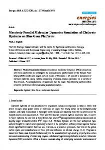
DSMC model of an in-line coater
Domain decomposition in YZ plane DSMC gas flow model comprises - Total volume of 7.5 m³ - 1005 Volume elements
Connecting slots between M8-M9 and M9-M10
y
37.5 25
Area above glass substrate
75
150
ZP3
ZP2
ZP1
ZM
ZV1
ZV2
ZV3
425
300
600
1700
600
300
425
Area of glass substrate transport
ZP3
ZP2
ZP1
ZPM
ZV1
ZV2
ZV3
450
275
600
1700
600
275
450
Area between transpo rt rolls
z
Pfl, Sie, Szy 2006-09-20
Fraunhofer Institut Schicht- und Oberflächentechnik
Euro-PVM/MPI 2006, Sept. 17-20, 2006
Outline 1.
Introduction
2.
Details of parallel DSMC implementation
3.
DSMC model of an in-line coater
4.
3D Gas flow simulation with moving glass substrates
5.
Summary and outlook Pfl, Sie, Szy 2006-09-20
Fraunhofer Institut Schicht- und Oberflächentechnik
3D Gas flow simulation with moving substrate
DSMC implementation data Linux cluster at Fraunhofer IST Implementation details �
� � � � �
�
Linux cluster with 5 nodes à 2 Opteron-250 (2.4 GHz) processors and GBit ethernet 4 GB (8x512 MB) of memory for each node Debian sarge, g++ 3.3.5, pvm 3.4.1 Time cycle = 2.5x10⁻⁵ s 150000 cycles for first glass position 25000 cycles for each of 56 subsequent glass positions (+10000 cycles for time averaging) Approx. 106 simulation particles in total Pfl, Sie, Szy 2006-09-20
Fraunhofer Institut Schicht- und Oberflächentechnik
3D Gas flow simulation with moving substrate
DSMC model of BigMag coater Pressure distribution around sputter compartment M9 Argon-Druck [mPa] 180.0 170.0 160.0 150.0 140.0 130.0 120.0 110.0 100.0 90.0 80.0 70.0 60.0
M10
M9
M8
Without glass substrate Ohne Glassubstrat
Pfl, Sie, Szy 2006-09-20
Fraunhofer Institut Schicht- und Oberflächentechnik
3D Gas flow simulation with moving substrate
DSMC model of BigMag coater Influence of glass substrate Argon-Druck [mPa] 180.0 170.0 160.0 150.0 140.0 130.0 120.0 110.0 100.0 90.0 80.0 70.0 60.0
M10
M9
M8
WithGlassubstrat glass substrate Mit
Pfl, Sie, Szy 2006-09-20
Fraunhofer Institut Schicht- und Oberflächentechnik
3D Gas flow simulation with moving substrate
Substrate movement Influence of substrate movement on total pressure in M10 Simulation vs. Measurement
•
•
Good agreement between simulation and experiment
127
Experimental values taken from coign of chamber M10
126
Absolute values of pressure measurements are very difficult to obtain
Pressure [mPa]
•
128
Deposition range
125 124 BigMag-Logfile: Si3N4 deposition Ionivac BAG 100 in M10 scaled by factor 1/2.79 DSMC simulation in M10 (Ar pressure)
123 122 121 0.0
0.5
1.0
1.5
Glass front position [m]
Fraunhofer Institut Schicht- und Oberflächentechnik
2.0 Pfl, Sie, Szy 2006-09-20
3D Gas flow simulation with moving substrate
DSMC model of BigMag coater Load balancing Load balance � Equally distributed load per process � Load can be either estimated from total number of particles or measured via the clock() function during test cycles � Auxiliary condition: Minimizing the number of communication paths over network (typically 2000�200) � »Simulated Annealing«
M
Load balance by number of particles
Load balance by averaged CPU clock() results
Time for 1000 cycles [s]
Time for 1000 cycles [s]
η Speedup [%]
η Speedup [%]
1
438
438
2
297
74
272
81
3
255
57
219
67
4
241
45
170
64
5
213
41
150
58
6
169
43
141
52
7
148
42
122
51
8
152
36
114
49
9
127
38
122
40
10
145
30
118
37 Pfl, Sie, Szy 2006-09-20
Fraunhofer Institut Schicht- und Oberflächentechnik
3D Gas flow simulation with moving substrate
Heuristic simulation of reactive magnetron sputtering •
•
Simplified model of the whole process Model of in-line coater uses 2D pressure distribution averaged along target direction (z-Axis)
�
Pflug et al., Proc. 47th SVC Tech. Conf. (2004) 155-60.
�
Pflug et al.; Proc. 49th SVC Tech. Conf. (2006) 14-20.
_ Relative thickness deviation ∆ t / t [%]
Substrate movement Heuristic simulation of resulting film thickness profile 2.5 2.0
Heuristic model Reactive ZnO, 11.02.2004, center Reactive SiO2, 16.06.2004, center
1.5 1.0 0.5 0.0 -0.5 -1.0 -1.5 0.0
Fraunhofer Institut Schicht- und Oberflächentechnik
0.2
0.4
0.6
0.8
Location ~x on substrate [m]
1.0 Pfl, Sie, Szy 2006-09-20
3D Gas flow simulation with moving substrate
� “Phase shift” in gas pressure distribution between different positions along target axis.
Argon pressure [mPa]
3D gas pressure distribution Phase shift at different positions within chamber 0.181 0.180 0.179 0.178 0.177 0.176 0.175 0.174 0.173 0.172 0.171 0.170 0.169 0.168 0.167 0.166
Segments ZP3 / ZVP ZP1 / ZV1 ZM
0.0
0.5
y
x150
1.5
2.0
Position of glass front [m]
Connecting slots between compartments 37.5 25
1.0
Upper area
75
x
x
x
x
ZP3
ZP2
ZP1
ZM
ZV1
ZV2
ZV3
425
300
600
1700
600
300
425
Glass substrate
ZP3
ZP2
ZP1
ZPM
ZV1
ZV2
ZV3
450
275
600
1700
600
275
450
Lower area z
Fraunhofer Institut Schicht- und Oberflächentechnik
Pfl, Sie, Szy 2006-09-20
Euro-PVM/MPI 2006, Sept. 17-20, 2006
Summary 1.
A high precision parallel DSMC code for rarefied gas flow simulation has been developed at Fraunhofer IST
2.
The DSMC code has been applied to an in-line coater with a moving substrate
3.
The simulation is in good agreement with pressure measurements. A 2D heuristic model derived from the DSMC simulations is partially capable of describing the resulting film thickness distribution on substrate
4.
In many cases a 2D heuristic model is not an appropriate description for large in-line coaters. This is most probably caused by the phase shift in the XZ-pressure distribution between different locations along target axis
Pfl, Sie, Szy 2006-09-20
Fraunhofer Institut Schicht- und Oberflächentechnik
Euro-PVM/MPI 2006, Sept. 17-20, 2006
Outlook 1.
Network latency of GBit ethernet cards seems to be a significant limitation. This will be further investigated.
2.
A PIC-MC plasma simulation system has been implemented based on the parallel DSMC code � M. Siemers et al., Proc. 49th SVC Tech. Conf. (2006) 60-63.
Pfl, Sie, Szy 2006-09-20
Fraunhofer Institut Schicht- und Oberflächentechnik
49th Annual SVC Technical Conference 2006
Thank you very much for your attention!
This work has partially been funded by
Bundesministerium für Bildung und Forschung (BMBF) and
VolkswagenStiftung Hannover
Pfl, Sie, Szy 2006-09-20
Fraunhofer Institut Schicht- und Oberflächentechnik
Euro-PVM/MPI 2006, Sept. 17-20, 2006
Backup slides
Pfl, Sie, Szy 2006-09-20
Fraunhofer Institut Schicht- und Oberflächentechnik
Introduction / Motivation
Low-E coatings: Demand on film thickness homogeneity Influence of film thickness deviations for double-Ag-low-E Dependency of color coordinates a*, b* on thickness 79
79
3.5 2.5
78 77
Ag d1
d2 [nm]
approx. 180 nm
NiCrOx
-3.0 -3.5 -4.0
78
-2.5
3.0
-1.0
2.0
-1.5
0.50
0 0.50
75
4.0
3.0
1.0
77
-0.50
76
3.5
2.5
-2.0
d2 [nm]
Example: SnO2 based double-Ag low-E stack
1 nm
1.5
2.0 1.5
76 -1.0
75
0
-2.5
SnO2
74
d2
74
-3.0 -1.5
1.0
-0.50
-2.0 -3.5
43
44
d3
45
46 47 d1 [nm]
48
43
44
45
46 47 d1 [nm]
48
Demand on large area coatings: (substrate size: 6.0*3.21 m²)
Float dAg + dNiCrOx = 9 nm
�
Fraunhofer Institut Schicht- und Oberflächentechnik
Pfl, Sie, Szy 2006-09-20
Details of parallel DSMC imlementation
»Direct Simulation Monte Carlo« (DSMC) - method Overall calculation schedule Initialisation Geometry
Time cycles Volume elements
Species and collision parameters
Particle move ment during interval [t, t+δ t]
Mesh of sub cells Boundary surfaces and pumping
Save final state (= velocitiy, coordin ates of each sim ulation particle) in to sta te file Perform Navg cycles of tim e averaging
Results
Initial particle distribution Random (M axwellian distribu tion)
Evaluation
New particle generation
N time cycles Collision treatment δt = 10-7...10-4 s during interval [t , t+δ t]
Averaged net flows of pa rticles Density Averaged velocity compon ents , ,
Restore from state file Data loggi ng (every m steps)
Averages square velocity
Pfl, Sie, Szy 2006-09-20
Fraunhofer Institut Schicht- und Oberflächentechnik