Wawrzynek. Cornell Fracture Group, Rhodes Hall, Cornell University, Ithaca, NY 14853. CS Department, Upson Hall, Cornell University, Ithaca, NY 14853.
Parallel FEM Simulation of Crack Propagation – Challenges, Status, and Perspectives List of Authors (in alphabetical order): Bruce Carter, Chuin-Shan Chen, L. Paul Chew, Nikos Chrisochoides, Guang R. Gao, Gerd Heber, Antony R. Ingraffea, Roland Krause, Chris Myers, Demian Nave, Keshav Pingali, Paul Stodghill, Stephen Vavasis, Paul A. Wawrzynek Cornell Fracture Group, Rhodes Hall, Cornell University, Ithaca, NY 14853 CS Department, Upson Hall, Cornell University, Ithaca, NY 14853 CS Department, University of Notre Dame, Notre Dame, IN 46556 EECIS Department, University of Delaware, Newark, DE 19716
1 Introduction Understanding how fractures develop in materials is crucial to many disciplines, e.g., aeronautical engineering, material sciences, and geophysics. Fast and accurate computer simulation of crack propagation in realistic 3D structures would be a valuable tool for engineers and scientists exploring the fracture process in materials. In this paper, we will describe a next generation crack propagation simulation software that aims to make this potential a reality. Within the scope of this paper, it is sufficient to think about crack propagation as a dynamic process of creating new surfaces within a solid. During the simulation, crack growth causes changes in the geometry and, sometimes, in the topology of the model. Roughly speaking, with the tools in place before the start of this project, a typical fracture degrees of freedom, using boundary elements, would take about 100 hours on a stateanalysis at a resolution of of-the-art single processor workstation. The goal of this project is it to create a parallel environment which allows the same analysis to be done, using finite elements, in 1 hour at a resolution of degrees of freedom. In order to attain this level of performance, our system will have two features that are not found in current fracture analysis systems: Parallelism – Current trends in computer hardware suggest that in the near future, high-end engineering workstations will be 8- or 16-way SMP “nodes”, and departmental computational servers will be built by combining a number of these nodes using a high-performance network switch. Furthermore, the performance of each processor in these nodes will continue to grow. This will happen not only because of faster clock speeds, but also because finer-grain parallelism will be exploited via multi-way (or superscalar) execution and multi-threading. Adaptivity – Cracks are (hopefully) very small compared with the dimension of the structure, and their growth is very dynamic in nature. Because of this, it is impossible to know a priori how fine a discretization is required to accurately predict crack growth. While it is possible to over-refine the discretization, this is undesirable, as it tends to dramatically increase the required computational resources. A better approach is to adaptively choose the discretization refinement. Initially, a coarse discretization is used, and, if this induces a large error for certain regions of the model, then the discretization is refined in those regions. The dynamic nature of crack growth and the need to do adaptive refinement make crack propagation simulation a highly irregular application. Exploiting parallelism and adaptivity presents us with three major research challenges, developing algorithms for parallel mesh generation for unstructured 3D meshes with automatic element size control and provably good element quality, implementing fast and robust parallel sparse solvers, and determining efficient schemes for automatic, hybrid h-p refinement.
1
To tackle the challenges of developing this system, we have assembled a multi-disciplinary and multi-institutional team that draws upon a wide-ranging pool of talent and the resources of 3 universities.
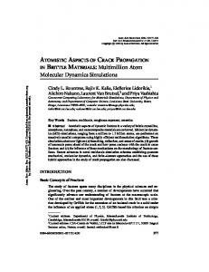
2 System Overview Figure 1 gives an overview of a typical simulation. During pre-processing, a solid model is created, problem specific FRANC3D Live Prediction
Crack Propagation
Boundary Conditions
Fracture Analysis
Solid Model
Introduce Flaws
YES NO Acceptable Error?
Unstructured Refinement
Structured Refinement
Volume Mesh
Finite Element Formulation
Increase Order of Basis Functions Estimate Errors
Iterative Solution
Figure 1: Simulation loop. boundary conditions (displacements, tractions, etc.) are imposed, and flaws (cracks) are introduced. In the next step, a volume mesh is created, and (linear elasticity) equations for the displacements are formulated and solved. An error estimator determines whether the desired accuracy has been reached, or further iterations, after subsequent adaptation, are necessary. Finally, the results are fed back into a fracture analysis tool for post-processing and crack propagation. Figure 1 presents the simulation loop of our system in its final and most advanced form. Currently, we have sequential and parallel implementations of the outer simulation loop (i.e., not the inner refinement loop) running with the following restrictions: currently, the parallel mesher can handle only polygonal (non-curved) boundaries, which can be handled by the sequential meshers though (see section 3). We have not yet implemented unstructured h-refinement and adaptive p-refinement, although the parallel formulator can handle arbitrary p-order elements.
3 Geometric Modeling and Mesh Generation The solid modeler used in the project is called OSM. OSM, as well as the main pre- and post-processing tool, FRANC3D, is freely available from the Cornell Fracture Group’s website [12]. FRANC3D - a workstation based FRacture ANalysis Code for simulating arbitrary non-planar 3D crack growth - has been under development since 1987, with hydraulic fracture and crack growth in aerospace structures as the primary application targets since its inception. While there are a few 3D fracture simulators available and a number of other software packages that can model cracks in 3D structures, these are severely limited by the crack geometries that they can represent (typically planar elliptical or semi-elliptical only). FRANC3D differs by providing a mechanism for representing the geometry and topology of 3D structures with arbitrary non-planar cracks, along with functions for 1) discretizing or meshing the structure, 2) attaching boundary conditions at the geometry level and allowing the mesh to inherit these values, and 3) modifying the geometry to allow crack growth but with only local re-meshing required to complete the model. The simulation process is controlled by the user via a graphic user-interface, which includes windows for the display of the 3D structure and a menu/dialogue-box system for interacting with the program. The creation of volume meshes for crack growth studies is quite challenging. The geometries tend to be complicated because of internal boundaries (cracks). The simulation requires smaller elements near each crack front in order to accurately model high stresses and curved geometry. On the other hand, larger elements might be sufficient away 2
from the crack front. There is a considerable difference between these two scales of element sizes, which amounts to three orders of magnitude in real life applications. A mesh generator must provide automatic element size control and give certain quality guarantees for elements. The mesh generators we studied so far are QMG by Steve Vavasis [15], JMESH by Joaquim Neto [11], and DMESH by Paul Chew [15]. These meshers represent three different approaches: octree-algorithm based (QMG), advancing front (JMESH), and Delaunay mesh (DMESH). QMG and DMESH come with quality guarantees for elements in terms of aspect ratio. All these mesh generators are sequential and give us insight into the generation of large “engineering quality” meshes. We decided to pursue the Delaunay mesh based approach first for a parallel implementation, which is described in [5]. Departing from traditional approaches, we simultaneously do mesh generation and partitioning in parallel. This not only eliminates most of the overhead of the traditional approach, it is almost a necessary condition to do crack growth simulations at this scale, where it is not always possible or too expensive to keep up with the geometry changes by doing structured h-refinement. The implementation is a parallelization of the so-called Bowyer-Watson (see the references in [5]) algorithm: given an initial Delaunay triangulation, we add a new point to the mesh, determine the simplex containing this point and the point’s cavity (the union of simplices with non-empty circumspheres), and, finally, retriangulate this cavity. One of the challenges for a parallel implementation is that this cavity might extend across several submeshes (and processors). What looks like a problem, turns out to be the key element in unifying mesh generation and partitioning: the newly created elements, together with an adequate cost function, are the best candidates to do the “partitioning on the fly”. We compared our results with Chaco and MeTis in terms of equidistribution of elements, relative quality of mesh separators, data migration, I/O, and total performance. Table 1 shows a runtime comparison between ParMeTis with PartGeomKway (PPGK) and, our implementation, called SMGP, on 16 processors of an IBM SP2 for meshes of up to 2000K elements. The numbers behind SMGP refer to different cost functions used in driving the partitioning [5]. Mesh Size 200K 500K 1000K 2000K
PPGK 90 215 439 1232
SMGP0 42 65 97 133
SMGP1 42 87 160 310
SMGP2 42 64 91 110
SMGP3 42 62 94 135
Table 1: Total run time in seconds on 16 processors.
4 Equation Solving and Preconditioning We chose PETSc [2,14] as the basis for our equation solver subsystem. PETSc provides a number of Krylov space solvers, and a number of widely-used preconditioners. We have augmented the basic library with third party packages, including BlockSolve95 [8] and the Barnard’s SPAI [3]. In addition, we have implemented a parallel version of the Global Extraction Element-By-Element (GEBE) preconditioner [7] (which is unrelated to the EBE preconditioner of Winget and Hughes), and added it to the collection using PETSc’s extension mechanisms. The central idea of GEBE is to extract subblocks of the global stiffness matrix associated with elements and invert them, which is highly parallel. The ICC preconditioner is frequently used in practice, and is considered to be a good preconditioner for many elasticity problems. However, we were concerned that it would not scale well to the large number of processors required for our final system. We believed that GEBE would provide a more scalable implementation, and we hoped that it would converge nearly as well as ICC. In order to test our hypothesis, we ran several experiments on the Cornell Theory Center SP-2. The preliminary performance results for the gear2 and tee2 models are shown in Tables 2 and 3, respectively. (gear2 is a model of a power transmission gear with a crack in one of its teeth. tee2 is a model of a T steel profile). For each model, we ran the Conjugant Gradient solver with both BlockSolve95’s ICC preconditioner and our own parallel implementation reduction of the residual of GEBE on 8 to 64 processors. (The iteration counts in Tables 2 and 3 correspond to a error, which is completely academic at this point.) The experimental results confirm our hypothesis: GEBE converges nearly as quickly as ICC for the problems that we tested. Our naive GEBE implementation scales much better than BlockSolve95’s sophisticated ICC implementation.
3
Prec. Type ICC GEBE ICC GEBE ICC GEBE ICC GEBE
Nodes 8 8 16 16 32 32 64 64
Prec Time(s) 17.08 9.43 15.47 6.71 8.51 3.73 11.00 4.74
Time Per Iteration (s) 0.2 0.19 0.27 0.11 0.32 0.08 0.28 0.07
Iters. Prec. Type ICC GEBE ICC GEBE
416 487 422 486 539 485 417 485
Nodes 32 32 64 64
Prec Time(s) 30.00 35.70 23.60 7.60
Time Per Iteration (s) 0.29 0.21 0.29 0.12
Iters. 2109 2421 2317 2418
Table 3: Tee2 (319,994 unknowns)
Table 2: Gear2 (79,656 unknowns)
5 Adaptivity Understanding the cost and impact of the different adaptivity options is the central point in our current activities. We are in the process of integrating the structured (hierarchical) h-refinement into the parallel testbed, and the final version of this paper will contain more results on that. Our implementation follows the approach of Biswas and Oliker [4] and currently handles tetrahedra, while allowing enough flexibility for an extension to non-tetrahedral element types. Error Estimation and Adaptive Strategies. For relatively simple, two-dimensional problems, stress intensity factors can be computed to an accuracy sufficient for engineering purposes with little mesh refinement by proper use of singularly enriched elements. There are many situations though when functionals other than stress intensity factors are of interest or when the singularity of the solution is not known a priori. In any case the engineer should be able to evaluate whether the data of interest have converged to some level of accuracy considered appropriate for the computation. It is generally sufficient to show, that the data of interest are converging sequences with respect to increasing degrees of freedom. Adaptive finite element methods are the most efficient way to achieve this goal and at the same time they are able to provide estimates of the remaining discretization error. We define the error of the finite element and a possible measure for the discretization error is the energy norm, solution as Following an idea of Babuˇska and Miller [1] the error estimator introduced by Kelly et.al. [9,6] is derived by inserting the finite element solution into the original differential equation system and calculating a norm of the residual using interpolation estimates. An error indicator computable from local results of one element of the finite element solution is then derived and the corresponding error estimator is computed by summing the contribution of the error indicators over the entire domain. The error indicator is computed with a contribution from the interior residual of the element and a contribution of the stress jumps on the faces of an element. Details on the computation of the error estimator from the finite element solution can be found in [10]. Control of a Mesh Generator. For a sequence of adaptively refined and quasi optimal meshes, the rate of convergence is independent of the smoothness of the exact solution. A mesh is called quasi optimal if the error associated with each element is nearly the same. The goal of an adaptive finite element algorithm is to generate a sequence of quasi optimal meshes by equilibrating the estimated error until a prescribed accuracy criterion is reached. Starting from an initial mesh, error indicators and the error estimator are computed in the post-processing step of the solution from the estimated error, the present phase. The idea is then to compute for each element the new element size element size and the expected rate of convergence.
6 Future Work The main focus of our future work will be on improving the performance of the existing system. The Cornell Fracture Group is continuously extending our test-suite with new real world problems. We are considering introducing special elements at the crack tip, and non-tetrahedral elements (hexes, prisms, pyramids) elsewhere. The linear solver, after proving its robustness, will be wrapped into a Newton-type solver for nonlinear problems. Among the newly introduced test problems are some that can be made arbitrarily ill-conditioned (long thin plate or tube models with cracks in them) in order to push the iterative methods to their limits. We are exploring new preconditioners (e.g., support tree preconditioning), and multigrid, as well as sparse direct solvers, to make our environment 4
more effective and robust. We have not done yet any specific performance tuning, like locality optimization. This is not only highly platform dependent, but also has to be put in perspective to the forthcoming runtime optimizations, like dynamic load balancing. We are following with interest the growing importance of latency tolerant architectures in the form of multithreading and exploring for which parts of the project multithreaded architectures are the most beneficial. Finally, there is a port of our code base to the new 256 node NT cluster at the Cornell Theory Center underway.
7 Conclusions At present, our project can claim two major contributions. The first is our parallel mesher/partition, which is the first practical implementation of its kind with quality guarantees. This technology makes it possible, for the first time, to fully automatically solve problems using unstructured h-refinement in a parallel setting. The second major contribution is to show that GEBE outperforms ICC, at least for our problem class. We have shown that, not only does GEBE converge almost as quickly as ICC, it is much more scalable in a parallel setting than ICC. We believe that GEBE, not ICC, is the yardstick against which other parallel preconditioners should be measured. And finally, our first experimants indicate that we should be able to meet our project’s performance goals. We are confident that, as we run our system on larger and faster machines, as we further optimize each of the subsystems, and as we incorporate adaptive h- and p-refinement, we will reach our performance goals.
References [1] I. Babuˇska and A. Miller, “A-posteriori error estimates and adaptive techniques for the finite element method,” Technical Report Tech. Note BN–968, University of Maryland, Inst.for Physics, Sci. and Tech., 1981. [2] S. Balay, W.D. Gropp, L. Curfman McInnes, and B.F. Smith, “Efficient management of parallelism in objectoriented numerical software libaries”, In E. Arge, A.M. Bruaset, and H.P. Langtangen, editors, Modern Software Tools in Scientific Computing, Birkhauser Press, 1997. [3] S.T. Barnard and R. Clay, “A portable MPI implementation of the SPAI preconditioner in ISIS++”, Eighth SIAM Conference for Parallel Processing for Scientific Computing, March 1997. [4] R. Biswas and L. Oliker, “A new procedure for dynamic adaption of three-dimensional unstructured grids”, Applied Numerical Mathematics, 13:437–452, 1994. [5] N. Chrisochoides and D. Nave, “Simultaneous mesh generation and partitioning for Delaunay meshes”, In 8th Int’l. Meshing Roundtable, 1999. [6] J.P. de S.R. Gago, D.W. Kelly, O.C. Zienkiewicz, and I. Babuˇska, “A posteriori error analysis and adaptive processes in the finite element method: Part II – Adaptive mesh refinement”, International Journal for Numerical Methods in Engineering, 19:1621–1656, 1983. [7] I. Hladik, M.B. Reed, and G. Swoboda, “Robust preconditioners for linear elasticity FEM analyses”, International Journal for Numerical Methods in Engineering, 40:2109–2127, 1997. [8] M.T. Jones and P.E. Plassmann, “Blocksolve95 users manual: Scalable library software for the parallel solution of sparse linear systems”, Technical Report ANL-95/48, Argonne National Laboratory, December 1995. [9] D.W. Kelly, J.P. de S.R. Gago, O.C. Zienkiewicz, and I. Babuˇska, “A posteriori error analysis and adaptive processes in the finite element method: Part I – Error analysis”, International Journal for Numerical Methods in Engineering, 19:1593–1619, 1983. [10] R. Krause, “Multiscale Computations with a Combined - and -Version of the Finite Element Method”, PhD thesis, Universit¨at Dortmund, 1996. [11] J.B.C. Neto et al., “An Algorithm for Three-Dimensional Mesh Generation for Arbitrary Regions with Cracks”, submitted for publication. [12] http://www.cfg.cornell.edu/. [13] http://www.cs.cornell.edu/People/chew/chew.html. [14] http://www.mcs.anl.gov/petsc/index.html. [15] http://www.cs.cornell.edu/vavasis/vavasis.html.
5