Journal of Electrical Engineering www.jee.ro
Parallel Fuzzy Logic Controllers for Independent Control of Two Permanent Magnet Synchronous Motors fed by a Five Leg Inverter for Electric Vehicles V.Krishnakumar1 V.Kamaraj2 S.Jeevananthan3 Research scholar, SSN College of Engineering, Kalavakam, Tamil Nadu. 2 Professor and Head, Department of Electrical and Electronics Engineering, SSN College of Engineering, Kalavakam, Chennai. 3 Associate Professor, Department of Electrical and Electronics Engineering, Pondicherry Engineering College, Pondicherry, INDIA. E-mail:
[email protected],
[email protected],
[email protected] 1
Abstract:Multi-motor multi-phase converter system can be composed by converter supplying several machines, which occupy an persona in industry applications such as electric power train, textile paper industries and autonomous mobile, where the general philosophy is a (2n+1) leg inverter can feed 'n' number of three phase motors. In this paper, the parallel fuzzy logic controllers (FLCs) are developed to control the speed of the two permanent magnet synchronous motors (PMSMs), which are driven by a five leg inverter (FLI). The FLI drive for two motors in the electrical vehicle/hybrid electric vehicles (EV/HEV) employs reduced component count (one leg less) due to the sharing of common leg amid the motors. The coincident control of two independent rated PMSMs (a traction motor to deliver the driving force for the vehicle and a compressor motor for the air-conditioning) through a single drive is cumbersome. The triumph of the designed two parallel FLCs is tested in MATLAB/Simulink environment and compared with the Ziegler-Nichols method tuned parallel proportional integral controllers (PICs). The time response analysis such as startup speed, peak over shoot, rise time, delay time and settling time have been evaluated. Simulation results verify the feasibility and validity of the proposed parallel FLC for the FLI drive, which shows decoupled operation of
two PMSMs and performances.
good
static/dynamic
Keywords- Parallel Fuzzy Logic Controller, Five Leg Inverter, Permanent Magnet Synchronous Motor, Current Reference Expanded Two Arm Modulation (CRETAM). 1 Introduction The electrical vehicle/hybrid electric vehicles (EV/HEV) requires dual electrical drives viz. a traction motor to deliver the driving force for the vehicle and a compressor motor for the air-conditioning [1]. Normally it entails two motor drives each associated with a three phase voltage source inverter (VSI) to independently control the motors. Each three phase VSI has six switches and hence totally twelve switches are required to drive two motor, which occupies considerable space. So to reduce the installation space and cost of inverter the Five Leg Inverter (FLI) has been proposed to drive two different rated motor. However this drive system does not affect the performance characteristics of six leg inverter (Two three phase inverters) [2]-[4]. Availability of permanent magnet materials like neodymium (Nd), samarium(sm), cobalt (Co) etc. has created attention on permanent magnet motors, which are best suited for the automotive industries. Because of their better
1
Journal of Electrical Engineering www.jee.ro
dynamic characteristics, higher efficiency, lower acoustic noises and vibration, they replaces conventional induction motors [5][6]. As mentioned earlier, the EV/HEV requires more than one motor i.e traction drive to deliver torque to accelerate the vehicle and compressor drive to deliver torque to actuate the air conditioning system [7]. The PMSM fed by FLI has been employed for automation in factory equipment’s as well. The independent vector control has been performed to control the two three phase PMSM. Higher efficiency, better dynamic performance and weight saving are the major importance in choosing PMSM. Instead of two drive circuits for operating dual PMSM, single drive circuit has been incorporated for driving two PMSM [8]. The digital signal processor (DSP) based integrated control of dual inverter has been proposed. The neutral point of the main traction motor has been extended for the auxiliary motor. Hence the reduction in inverter leg has been achieved [9]. The integrated inverter drives traction motor and compressor motor, which has been decreases the drive cost of the compressor motor. The neural point is shared by both traction and compressor motor[10]. The FLI has been presented to drive five phase induction motor drive extensively used for high power applications.The field programmable gate array (FPGA) realization of space vector pulse width modulation (SVPWM) technique has been developed to drive the FLI [11]. The new PWM technique has been proposed, which generates modulation signals for FLI from the modification of appropriate three phase modulation signals [12]. The sensor less technique has been proposed to drive dual PMSMs independently. This aims to eradicate the practice of using speed sensor and minimizes the switch count. The performance of dual PMSM drive has been
simulated and the results confirm good speed regulation [13]. The vector control of a three-phase PMSM along with a indirect flux oriented controller approach has been presented [14]. The attainable speed performance is obtained by utilizing the model reference adaptive fuzzy logic controller (FLC) which results precise control and better performance. The four switch three phase inverter control of interior type PMSM with fuzzy logic seed controller has been proposed [15]. The experimental result evident that the FLC are acceptable for high performance speed drive applications. The seed control of FLI for five phase induction motor using FLC has been presented [16]. The speed control algorithm has been successfully implemented in real time and results better dynamic operation.The single phase inverter fed dual PMSM drive has been proposed. The FLC proposed here uses only 9 rules instead of 49 rules [17]. The independent sensor less control of dual PMSM based FLI has been presented. The proposed approach eliminates the speed sensor and reduces the switch count. The model reference adaptive control speed estimation has been presented [18]. The single voltage source inverter with multiphase, parallel connected dual drive has been proposed to improve the dynamic performance of the machines. The experimental result verifies has been presented [19]. However proposed work suffers number of shortcoming, such as harmonics, torque ripple which prevent its industrial applications. The common mode voltage in five phase inverter has been reduced by implementing a simple carrier based PWM (CBPWM). With the help of proposed coupled inductor inverter (CII) by enhancing adjacent modulating waveform and non-adjacent modulating wave from, the common mode voltage has been reduced [20].
2
Journal of Electrical Engineering www.jee.ro
The main objective of the proposed work is implementation of parallel fuzzy logic speed controller for FLI control of two PMSM drive. The time domain specifications such as delay time, rise time, peak time, settling time and peak over shoot for startup torque response and step input response are tabulated for both PMSM 1 and PMSM 2 drive and the results are compared with standard proportional integral controller (PIC) using the MATLAB/Simulink tool. 2 Parallel FLC based FLI control of Two PMSMs
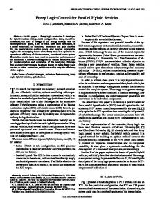
2.1 Proposed Drive System The block diagram representation of the proposed system, the FLI fed two PMSMs controlled by parallel FLC, is shown in Fig.1. The system consists of a FLI, two PMSMs, position sensors and the parallel FLC. The major importance in designing the FLC for integrated FLI fed two PMSM drive is worth due to the challenging requirement of independent control of PMSMs. That is they are of different ratings, and can be operated different load torque commands and also different speed commands.
Fig. 1 Integrated FLI fed two PMSM with parallel FLC
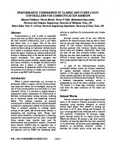
The configuration of parallel FLC integrated with independent vector control scheme to control two PMSM under current reference expanded two arm modulation (CRETAM) technique [21] is shown in Fig.2. In FLI the fifth leg is shared as a common leg by the main traction motor and auxiliary motor by assuming ids=0, which retains linearity between motor torque and current. The parallel fuzzy logic speed controller are utilized which compares reference speed with actual speed generates current component,
iqs*equivalent to torque. The CRETAM is a modulation technique, which requires current error to generate the pulses for FLI. The CRETAM technique is extended from expanded two arm modulation technique (ETAM) [21]. Usually it requires current error, which is obtained from the difference of actual sensed current and reference current. The current error signal is compared with reference signal waveform and to generate the pulses which are essential to turn on and turn off the switch in the leg.
3
Journal of Electrical Engineering www.jee.ro
Fig. 2 FLC implemented in FLI for independent vector control scheme
2.2 Development FLC From the literature, there are many controllers such as sliding mode controller, neural network controller, model reference adaptive controller, variable structure controller etc. have been employed in variable speed drives. Among them two controllers called PIC and FLC are the strong challengers. However, adopting any controller to control loop purely depend on mathematical model of motor. The mathematical expression is derived based on the assumption that the environmental and temperature changes are zero. But it is difficult to achieve experimentally. The PICs are enhanced in the control loops due to its simple design and easy accessibility. However, PIC has certain drawbacks such as noise, lower bandwidth, requires tedious (Ziegler-Nickols) tuning method for proper tuning. The PICs are sensitive to parameter variation, so it cannot be extended to nonlinear systems. Hence FLC has been
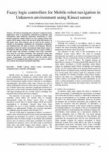
proposed which are insensitivity to parameter variation. Fig. 3 represents the basic block diagram of FLC which has various blocks required to control the desired performance of load. The FLC provides the superior control capability among various controllers. The FLC and artificial neural network intelligence control have becoming popular approach to non-linear systems. FLC is simplest approach, it requires three step/block procedure to regulate the speed error. The first block is input block which converts the input function into appropriate fuzzy set by a membership function. The second block is logic estimator, also called rule evaluator, which involves in processing the appropriate rules. The selected rule has been proceeded till the fuzzy operator attains the best suitable result. The final block is also called output block/defuzzification block which takes the crispness recuperate from fuzziness and finally, the combined result has been transformed into control function.
4
Journal of Electrical Engineering www.jee.ro
Fig. 3 Principle of fuzzy logic controller
As stated earlier, the proposed drives system involves two paralleling working FLC. Even though the membership function, rule base and defuzzification conditions are different amid the FLC, their development procedure is same. This section describes the representative case of FLC designed for main motor (PMSM-1) is detailed. Table 1 pictures the rule base of the designed FLC. Five linguistic variables are assigned viz. NBnegative big, NS-negative small, Z-zero, PSpositive small and PB-positive big. The fuzzy inputs (speed error and change in speed error) dwell in the range, which is the subsets of assumed membership function and have the fuzzified values between 0 and 1. The fuzzy rule patterned in Table 1 must be interpreted
properly. For example, IF ‘speed error is NB’ AND ‘change in speed error is PS’ THEN ‘change in output q axis current command is Z’. Selection of membership function plays important role, because it identifies how to map each point in the input spaces to a degree of membership between 0 and 1. In the proposed parallel FLCs, the Mamdani membership function is used as shown in Fig.6. The membership functions for change in speed, change in speed error and the output current commands are shown respectively in Fig.7, Fig.8 and Fig.9. Fig.10 and Fig.11 represent the rule selection and rule plot for FLC. Fig. 12 represents the surface view of the designed FLC.
Table 1 Fuzzy Rule Speed error, E
Change in speed error, CE
NB NS Z PS PB
NB NB
NS NB
Z NB
PS NS
PB Z
NB NB NS
NB NS Z
NS Z PS
Z PS PS
PS PB PB
Z
PS
PB
PB
PB
5
Journal of Electrical Engineering www.jee.ro
Fig. 6 Dimensioning the FLC
Fig. 7 Membership function for speed error
Fig. 8 Membership function for change in speed error
Fig. 9 Membership function for output q axis current command
6
Journal of Electrical Engineering www.jee.ro
Fig. 10 Rule selection for FLC
Fig. 11 Rules plot of FLC
Fig. 12 Surface view of fuzzy logic controller
7
Journal of Electrical Engineering www.jee.ro
3 Results and Discussions This section presents the thorough investigation of the developed drive system in MATLAB-Simulink environment. The system is schematized in MATLAB 2011a and simulated using ode dormand prince
solver. The specifications of the PMSMs are listed in the table 2 and the speed-torque requirements in the EV are as follows. The main motor (PMSM-1) needs to work in 3000rpm and (0.4-080rpm, while the requirements on auxiliary motor (PMSM-2) are 750rpm and (0.2-0.4) rpm.
Table 2. Specifications of motors Parameters PMSM-1 PMSM-2 Rated output power (kW) 0.25 0.25 Rated speed (rpm) 3000 750 Back EMF constant 62.2859 62.2859 (VL-L peak/krpm) No of Poles 4 4 Rated Torque (Nm) 0.8 1.7 Stator Resistance (Ω) 18.7 4.765 Stator d and q axis 0.014 0.02682 inductance (H) Inertia (Kg.m2) 2.26e-5 1.05e-4 Friction Factor (N.m.s) 1.349e-5 4.04e-5 The Fig.13 depicts the comparison of start up speed response of PMSM-1 and PMSM-2 with parallel FLCs and PICs. The Fig.14 depicts the comparison of startup torque response of PMSM1 and PMSM-2 with FLCs and PICs.
8
Journal of Electrical Engineering www.jee.ro
Fig 13 Start up speed response of PMSM1 and PMSM2
Fig. 14 Torque responses of PMSM1 and PMSM2
The time domain specifications (TDS) of the motors (PMSM-1 and PMSM-2) during startup transient of speed response are
presented in the Table 3. The delay time, rise time, peak time, settling time and peak overshoot values listed for both PICs and
9
Journal of Electrical Engineering www.jee.ro
FLCs. In adopting parallel FLCs, there is a considerable decrease in peak time and settling time compared to PIC as shown in Table 3. The PMSM-1 experiences 28.8% reduction in peak overshoot and PMSM-2 faces 76% reduction. Table 3. Speed response TDS comparison for PICs and FLCs in startup transient
Time Domain Specification Delay Time Rise Time Peak Time Settling Time Peak overshoot
PICs PMSM-1 PMSM-2 3000rpm/0.4nm 750/0.2Nm 0.0014*10-3 0.0015*10-3 -3 0.0025*10 0.0025*10-3 0.003*10-3 0.0032*10-3 0.25*10-3 0.01*10-3 435rpm 80.5rpm
The next interesting study is made with the step change in the load torque. The inhomogeneous torque reference changes assert the triumph of the parallel FLCs. The
FLCs PMSM-1 PMSM-2 3000rpm/0.4nm 750/0.2Nm 0.00125*10-3 0.0011*10-3 -3 0.0024*10 0.0021*10-3 0.0029*10-3 0.0026*10-3 0.1*10-3 0.095*10-3 310rpm 19.26rpm
step change for PMSM-1 is 0.4Nm to 0.2 Nm and for PMSM-2 is 0.4 Nm to 0.8 Nm at 0.25 seconds. The Fig.15 and Fig.16 depict respectively the speed and torque transients for such a step changes.
Fig. 15 Speed responses of PMSM-1 and PMSM-2 for the inhomogeneous torque step changes
10
Journal of Electrical Engineering www.jee.ro
Fig 16 Torque responses of PMSM-1 and PMSM-2 for the inhomogeneous torque step changes
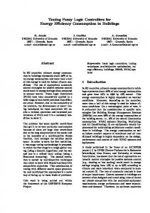
The Fig.17 represents enlarged view speed responses for the inhomogeneous torque step changes at 0.25seconds to facilitate the insight view of TDS values. The Fig. 18 represents step change in load torque from
0.8nm to 0.4nm desired torque response for PMSM1 and step change in load torque from 0.4nm to 0.2nm desired speed response for PMSM2. The TDS values are tabulated in Table 4.
(a) PMSM-1
11
Journal of Electrical Engineering www.jee.ro
(b) PMSM-2 Fig. 17 Enlarged view of speed responses at for the inhomogeneous torque step changes Table 4. Speed response TDS comparison for PICs and FLCs for step change in load torque - Combination 1
Time Domain Specification Delay Time Rise Time Peak Time Settling Time Peak overshoot
PIC PMSM-1 3000rpm/0.80.4nm 0.009*10-3 0.0014*10-3 0.0019*10-3 0.023*10-3 70rpm
FLC PMSM-2 750/0.40.2Nm 0.0014*10-3 0.0016*10-3 0.0021*10-3 0.031*10-3 130rpm
Transient study for another inhomogeneous step change combination is performed by changing the torque reference of PMSM-1
PMSM-1 3000rpm/0.8-0.4nm 0.00125*10-3 0.0024*10-3 0.0029*10-3 0.01*10-3 19rpm
PMSM-2 750/0.40.2Nm 0.0011*10-3 0.0014*10-3 0.002*10-3 0.0011*10-3 25.6rpm
from 0.8Nm to 0.4Nm and of PMSM-2 from 0.4Nm to 0.2Nm and pictured in Fig.18.
12
Journal of Electrical Engineering www.jee.ro
Fig 18 Step change in load torque (0.8-0.4/0.4-0.2Nm)
The Fig.19 represents speed response for step change in load torque from 0.4nm to 0.8nm for PMSM-1 and similar response of the PMSM-2 is diagrammed in Fig.20. The corresponding TDS values are enlisted in
Table 5. It is evident from the table that the PMSM -1 and PMSM-2 have reduced peak overshoots respectively 25.3% and 26.92% with FLCs than PICs. Also the settling time reduced about 18% and 35% respectively.
Fig.19 Enlarged view of speed responses for step torque change from 0.4Nm to 0.8Nm-PMSM-1
13
Journal of Electrical Engineering www.jee.ro
Fig.20 Enlarged view of speed responses for step torque change from 0.2Nm to 0.4Nm-PMSM-2
Table 5. Speed response TDS comparison for step change in load torque- Combination 2
Time Domain Specification Delay Time Rise Time Peak Time Settling Time Peak overshoot
PIC PMSM-1 3000rpm/0.40.8nm 0.0011*10-3 0.0015*10-3 0.0020*10-3 0.022*10-3 79rpm
FLC PMSM-2 750/0.20.4Nm 0.0019*10-3 0.0020*10-3 0.0025*10-3 0.017*10-3 26rpm
4 Conclusion This paper presented a parallel fuzzy logic controller (FLC) for the integrated traction and compressor drive to reduce the HVAC compressor drive cost in electric and hybrid electric vehicle (EV/HEV) applications. The drive system employs a five-leg inverter to drive a three-phase traction motor and a two-phase compressor motor. The common terminal of the twophase motor is tied to the neutral point of the three-phase traction motor to eliminate the requirement of a third phase leg. The cost of the compressor drive can be significantly
PMSM-1 3000rpm/0.4-0.8nm 0.0015*10-3 0.0024*10-3 0.0029*10-3 0.018*10-3 59rpm
PMSM-2 750/0.20.4Nm 0.0016*10-3 0.0018*10-3 0.0021*10-3 0.011*10-3 19rpm
lowered due to the elimination of one phase leg and additional part count reduction made possible by sharing the switching devices, DC bus filter capacitors, gate drive power supplies, and control circuit. Simulation and experimental results are included to verify that speed control of the two motors is independent from each other. The parallel FLC is implemented to independently control the speed of the two PMSM. The results of fuzzy logic controller based two PMSM is compared with the PIC. From the comparison the FLC results validates better performance than PIC. The
14
Journal of Electrical Engineering www.jee.ro
time domain specifications such as rise time, delay time, peak time, settling time, peak overshoot are calculated for stepped speed and torque responses for both PMSM are tabulated. References [1] Gui-jiasu and John.S. Hsu, “An Integrated Traction and Compressor Drive System for EV/HEV Applications,” Proceedings of the IEEE International Conference on Applied Power Electronics Conference and Exposition, (APEC'05), vol.2, pp.719725, March 2005. [2] Bose.B.K, “Power electronics and AC drives,” Prentice-Hall, chapter 2, pp.8694, 1986. [3] Gopal K. Dubey, “Fundamentals of Electric Drives,” Prentice-Hall, 1989. [4] R.Krishnan, “Electric Motor Drives Modeling, Analysis and Control,” Prentice- Hall, 2001. [5] R.Krishnan, “Permanent Magnet Synchronous and Brushless DC Motor Drives,” CRC Press, 2010. [6] P.Pillay and R.Krishnan, "Modeling of permanent magnet motor drives," IEEE Transactions on Industrial Electronics, vol.35, no.4, pp.537-541, November 1988. [7] P.Pillay and R.Krishnan, "Modeling, simulation and analysis of permanentmagnet motor drives. Part 1: The permanent-magnet synchronous motor drive," IEEE Transactions on Industry Applications, vol.25, no.2, pp.265-273, March 1989.
[8] Hiroyuki Enokijima, Kazuo Oka and Kouki Matsuse, “Independent Position Control of Two Permanent Magnet Synchronous Motor Drives Fed by a Five-Leg Inverter,” Journal of International Council on Electrical Engineering, vol.1, no.4, pp.400-404, 2011. [9] Lixin Tang and Gui-Jia Su, “HighPerformance Control of Two ThreePhasePermanent Magnet Synchronous Machines in anIntegrated Inverter for Automotive Applications,” Prepared by Oak Ridge National Laboratory, managed by UT-Battelle, LLC, for the U.S. Dept. of Energy under contract DEAC05-00OR22725, pp.1-7, 2006. [10] Gui-jiasu and John.S. Hsu, “A Five Leg Inverter for Driving a Traction Motor and a Compressor Drive,”IEEE Transactions on Power Electronics, vol.21, no.3, pp.687-692, May 2006. [11] G.Renukadevi and K.Rajambal, “Field programmable gate array implementation of space-vector pulse-width modulation technique forfive-phase voltage source inverter,” IET Power Electronics, vol. 7, no. 2, pp. 376–389, 2014. [12] M.Jones, S.N.Vukosavic, D.Dujic, E.Levi and P.Wright, “Five-leg inverter PWM technique for reduced switch count two-motor constant power applications” IET Electric.Power Applications, vol.2, no.5, pp.275-287, September 2008. [13] Zulkifilie Ibrahim, Jurifa Mat Lazi, MarizanSulaiman “Independent Speed Sensorless Control of DualParallel PMSM based on Five-Leg Inverter,” proceedings of the IEEE International
15
Journal of Electrical Engineering www.jee.ro
multi-conference on systems, signals and Devices, 2012. [14] Atif Iqbal, Haitham Abu-Rub and Hazem Nounou, “Adaptive fuzzy logiccontrolled surface mountpermanent magnet synchronous motor drive,” Taylor and Francis Systems Science & Control Engineering, Vol. 2, pp. 465– 475, May2014. [15] Z.M.S. El-Barbary, “Fuzzy logic based controller for five-phase inductionmotor drive system,” Alexandria Engineering Journal, Vol.51, pp.263-268,October 2012. [16] M. Nasir Uddin, Tawfik S. Radwan, and M. Azizur Rahman,“Fuzzy-LogicController-Based Cost-EffectiveFourSwitch Three-Phase Inverter-Fed IPMSynchronous Motor Drive System,” IEEE Transactions on Industry Applications, Vol. 42, no. 1, pp.21-30, January 2006.
Multidrive Systems With Single Inverter Supply,”IEEE Transactions on Industrial Electronics, vol. 56, no.6, pp. 2047-2057, 2009. [20] Cheng Tan, Dan Xiao, John Edward Fletcher and Muhammed Fazlur Rahman, “Carrier-Based PWM Methods With Common-Mode Voltage Reduction for Five-Phase Coupled Inductor Inverter,” IEEE Transactions on Industrial Electronics, vol. 63, no.1, pp. 526-537, January 2016. [21] V. Krishnakumar, V. Kamaraj, C. Adrien, “An integrated Drive for two PMSMs involved automotive applications and development of current reference expanded two arm modulation,” Circuits and Systems, vol. 7, no. 8.(In press)
[17] Jurifa Mat Lazi, Zulkifilie Ibrahim, Marizan Sulaiman, Fizatul Aini Patakor, and Siti Noormiza Mat Isa, “ Fuzzy Logic Speed Controller with Reduced RuleBase for Dual PMSM Drives,” International Journal of Electrical, Computer, Energetic, Electronic and Communication Engineering, Vol:5, no.5, pp.623-628, 2011. [18] Akshay M. Suryawanshi and Anant A. Kulkarni, “Fuzzy Logic Based Controller for Five Phase Induction Motor Drive System,” International Journal of Advances in Engineering & Technology,Vol. 8, Issue 1, pp. 20322044, 2015. [19] M. Jones, S. N. Vukosavic, and E. Levi, “Parallel-Connected Multiphase
16