platform is actuated through six linear drives that move six ..... Therefore, we use status flags for each box .... Orleans, USA), 2004. ... Cliffs, New Jersey, 1966.
Parameter Synthesis for Parallel Kinematic Machines from Given Process Requirements Andreas Pott, Tim Boye and Manfred Hiller Abstract Parallel kinematic machines (PKM) are complex systems which kinematic properties vary in the workspace. Normally the machine’s task implies requirements e. g. size of the workspace and dexterity that must be taken into account for the design of the machine. In this paper we demonstrate geometrical parameter synthesis based on interval analysis for the parallel kinematic machine with constant leg length Linapod. The proposed algorithm enables us to determine all parameter sets that fulfill given process requirements like size of the orientation workspace and a given upper bound on the kinematic dexterity of the machine. The use of interval analysis guarantees the validity of the results and makes the procedure robust against numerical instability. The method is extendable for additional process requirements.
1. INTRODUCTION The choice of appropriate geometrical dimensions is a key issue for parallel kinematic mechanisms (PKM) since the geometrical parameters have a major impact on the kinematic performance of the machine. In fact, the geometrical parameters are even more important than the machine architecture [3, 7]. Therefore, the determination of these parameters is essential for the design of parallel robots. In the past, many researchers have been working on methods to optimize PKMs with respect to different design goals. One important topic is the design of a PKM for a given workspace [4, 6]. But in general, we have to consider a broader set of requirements, e. g. for machine tools a high accuracy is necessary which is directly coupled to the need for a satisfying stiffness behavior. Regarding applications like high speed cutting (HSC) additional specifications in terms of achievable velocities and accelerations must be met. In this paper, we address the design and optimization of the parallel kinematic machine tool Linapod [13] which has legs with constant length. The determination of the workspace has been considered by several authors (e. g. [6, 12]). The quality of the
workspace is mostly described in terms of dexterity measures [14], which are normally based on the Jacobian J of the direct or inverse kinematics. Examples for frequently used measures are the eigenvalues λi , the determinant det(J) and the condition number κ . The force transmission is important for the design of the drives, but since velocity transmission and force transmission are coupled, both have to be considered simultaneously.
1.1. The Optimization Dilemma There are two major problems arising from optimization of complex multibody systems like PKMs [8] which lead to the following optimization dilemma: we have a large number of parameters and it is difficult to define an objective function that works properly for all requirements. Performance criteria are needed to compare machines designed from different sets of parameters. Given a complex set of required properties (e. g. workspace, stiffness) we need an objective function that rates these properties. At first we define performance indices that are capable of estimating the attributes. As these indices cannot be compared directly, we have to introduce weighting factors to suitably scale the indices. The weighing factors are additional free parameters of the system, which strongly influence the result of the optimization. In general, there is no deterministic way to find an appropriate choice for the weighting factors [3] and we cannot guarantee that the maximum of the objective function presents a machine with the required properties. Instead of searching a machine that is optimal with respect to an objective function composed of performance indices we propose to first seek for all machines that fulfill given process requirements. After determining all feasible designs decisions may be made which one is most suitable for our problem. We use interval analysis to check if certain requirements are satisfied within a range of parameters. This paper is organized as follows: in sec. 2 we give a short introduction to interval analysis. We then present the machine Linapod (sec. 3) which is subject to the parameter synthesis based on given requirements (sec. 4). Results of the synthesis are given in sec. 5 and we close the paper by
drawing the conclusions.
2. INTERVAL ANALYSIS Interval analysis [11] is an useful mathematical tool for the analysis [1, 2, 10, 12] and design [3, 9] of PKMs. With an appropriate library like BIAS/PROFIL [5] we carry out interval analysis similarly to normal computations. Let II = {x, x ∈ IR|x ≤ x} be the set of pairs of real number which are called intervals. The interval evaluation provides guaranteed bounds on the function with x, y, z ∈ II, z ≤ x ⋄ y ≤ z, ⋄ ∈ {+, −, ∗, ÷}, x ∈ [x, x], y ∈ [y, y]. Since there is an interval representation for all standard mathematical operators we may use common algebraic equations and evaluate them with interval analysis. If we evaluate an inequality f (y0 ) > 0, y0 ∈ IIn with interval analysis the result [ f , f ] is also an interval and the following three cases may occur: If the lower bound of f fulfills f > 0 the inequality holds for any y ∈ y0 and we call it valid. On the other hand, if the upper bound f < 0, no y ∈ y0 fulfills the inequality. Thus the interval y0 is invalid. In any other case we cannot make a statement for the whole interval and the interval is called uncertain. Since the interval evaluation of a function may overestimate the bounds, we neither know at this point if there are any valid or invalid values for y ∈ y0 . But we can reduce the size of the interval by bisection and repeat the evaluation for the smaller intervals until we get a reliable statement (valid or invalid) since the interval analysis converges to the algebra of real numbers as the width of the intervals approaches zero.
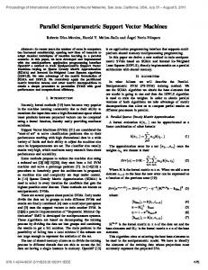
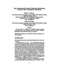
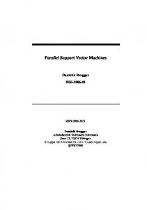
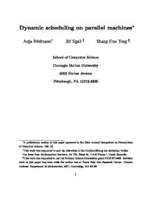
3. THE PKM LINAPOD The PKM Linapod (Fig. 1) is installed at the Institute for Control Engineering of Machine Tools and Manufacturing Units at the University Stuttgart (Germany) [13]. A mobile platform is actuated through six linear drives that move six legs of constant length li (i = 1, ..6 for the six legs). The frame K0 denotes the world coordinate system and KTCP is the frame that is attached to the mobile platform. The rotation matrix RTCP describes the relative orientation of KTCP with respect to K0 . The pivot points of the legs are denoted with Ai and Bi , respectively (Fig. 2). The actuators move on the straight line which is defined by the base point Ci and the direction ni . Using a vector loop yields the closure condition li2 = (ci + ni si − rTCP − RTCP bi )2 and we can solve for the unknown si r 1 . 2 si = −ni . d i ± (n d ) − d 2i − li2 , 4 i i
(1)
(2)
Fig 1. Computer Model of the Parallel Kinematic Tool Machine Linapod (ISW, Stuttgart, Germany)
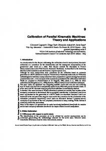
with d i = ci − rTCP − RTCP bi . The different signs in (2) correspond to different assembly modes of the PKM. Since we know how the PKM at hand is assembled we can choose typically the same sign for all six legs. In order to calculate the machine geometry dependent vectors ai , bi , ni , we have to introduce a parameterization that describes the variety of machines we want to study. Thus, the parameters of the Linapod (Fig. 1) are briefly introduced (Fig. 3). The base points Ci of the linear drives are distributed on a circle around K0 with radius rB . Since there are two drives mounted on one guideway the tangential offset ∆a tends to be small1 and has alternating directions for the upper and the lower drive. Negative values for ∆a are correlated to crossing bars while the bars are almost parallel for positiv ∆a. In the parameterization of the Linapod the length li of the legs is set to two different length lu and ll < lu for the upper legs and the lower legs, respectively. The pivot points on the platform Bi are arranged on circles in two parallel planes for the two groups of legs. The axis through the center of the circles is the z-axis of frame KTCP which is perpendicular to the plane of the circles. The radii of the circles are ru and rl for the upper and the lower circle, respectively. The distance between the planes is ∆h and the pivot points on the circles are mutually rotated by ∆α . 1 large values for ∆a are possible but require the construction of a machine with six instead of three guideways
Ui
Si
Ai
bar
Bi
ei
li
ai
platform Pi
bi KTCP
si
ni
r TCP ci
Ci
base
K0
Fig 2. Kinematic structure of a leg of the PKM Linapod. P, U , S denotes prismatic, universal and spherical joints, respectively.
to changes of the weights. Or in other words, the optimal design is a function of the weights gi and there is no deterministic way to calculate these weights gi . Finally, searching the extremum of the objective function means making a compromise between the requirements. But in reality a number of requirements are compulsory, i.e. a design that provides less than the requirement is useless but we do not need more because this may limit other properties. In contrast, one may ask to find all machines that fulfill the given requirements. Those machines are called the solution set of the design task. Thus, determining this set is a major part of the parameter synthesis. As pointed out above a number of requirements are compulsory requirements and they may be verified by evaluating inequalities. Thus, the presented approach towards parameter synthesis extensively exploits this idea.
4.1. Defining requirements
∆a guideway 1
leg 4
leg 1
ll
rl
lu y ∆α ru
rb x leg 3
leg 5
leg 2 guideway 2
In the past, it was shown how to verify a given workspace of a PKM with interval analysis [12]. Basically we extend this algorithm by calculating the set of the design parameters, that provides a given workspace for the machine. Then we may add additional requirements covering e.g. dexterity, link limits, and link interference in order to complete the design. 4.1.1. Reachable Orientation Workspace
leg 6 guideway 3
Fig 3. Parameterization of Linapod’s geometry
4. PARAMETER SYNTHESIS The classical approach to find an optimal machine is to introduce real numbers αi , called indices, that measure the performance of a machine with respect to certain aspect like dexterity, stiffness, workspace etc. In order to combine different requirements a weighted sum with the constants gi of these indices αi is considered as objective function and the task of optimal design is to find the minimum/maximum of this function. Although this idea is straightforward and has been applied to several problems there are a number of drawbacks. First, some of the requirements can hardly be expressed with only one number, e.g. shape of the workspace. Further on, the result of the optimization is very sensitive to the choice of the weights gi . Therefore, the optimal design is very sensitive
For the PKM Linapod (sec. 3) the kinematical reachable workspace is limited by the legs which have a constant length. From the inverse kinematics (2) we conclude that the radicand must be positive and we get 1 . 2 (n d ) − d 2i − li2 > 0. 4 i i
(3)
These conditions yield six inequalities which are collected in the system Φ > 0 and we call Φ the requirements of the design task. 4.1.2. Limits on the active and passive Joints Introducing limits on the active joints q and passive joints β is also based on the inverse kinematics. The angles of the joints are calculated by projecting the leg vector l onto certain planes that are defined by the assembly orientation of the passive joints. Again, we evaluate these equations with interval analysis and simply check if the results for q and β are within the allowed ranges [β min , β max ] for each joint. This results in two inequalities (one for the upper, one for the lower border) for each joint and we add these requirements to the requirement system Φ.
separately to be smaller than the given maximal transmission factor jmax and we receive
4.1.3. Dexterity Requirements The dexterity of robots and especially of PKMs plays an important role in their analysis and synthesis. Most of the considerations concerning dexterity are coupled to the calculation and analysis of the Jacobian matrix J =
∂ ϕ (q) ∂q
of
the manipulators kinematic function ϕ (q). Because there is no closed form solution for the direct kinematics of many types of PKMs researchers often switched to the inverse kinematics function which normally yields an explicit function and therefore an analytical form for the Jacobian. Typical indices for the dexterity are based on the eigenvalues, on the singular values, on the determinant or on the condition number. Note that all these dexterity measures are somehow coupled to each other and that their computation is either time consuming, iterative, or even both. Therefore, it is difficult to transform these conditions into the required inequalities that are needed for the proposed algorithm. Interval analysis based techniques were proposed to estimate bounds of the roots of parametric polynomial and therewith bounds for the eigenvalues of the Jacobian. Nevertheless, we suggest a different way that is related to the above mentioned dexterity measures. Let J be the Jacobian of the inverse kinematics of a PKM, thus mapping velocities of the platform w˙ to velocities in the drives q˙ of the mechanism. For a given velocity in world coordinates it is important not to exceed the maximal feasible velocity q˙ max of the actuators. Therefore, we need a relation q˙ max > J w˙ (4) Introducing compatible norms for the vectors yields the desired inequations ˙ ≤ ||J|| ||w||. ˙ ||˙qmax || = ||J w||
=
||A||∞
=
max |vi | v ∈ IRn
1≤i≤n
n
max
∑ |ai j |
1≤i≤n j=1
A ∈ IRn×n
max
∀ 1 ≤ i ≤ 6,
(8)
k=1
where jik are the elements of the Jacobian. Thus, we find a simple method to check for dexterity requirements over the whole workspace as inequalities enabling us to add the six additional requirements to our system Φ.
4.2. Requirement Verification over the Workspace Basically, the verification algorithm uses interval analysis in order to prove the validity of the constraints of a whole box at once. If we want to verify e.g. if a given machine covers a given workspace, we introduce the workspace as intervals in the parameters and evaluate the system of inequalities Φ(w) > 0. According to the considerations in sec. 2 we have to distinguish between three cases: if the interval evaluation of the function yields valid for all constraints, this box is valid and the verification is successful. If at least one inequality is invalid the procedure fails and we know that at least in the last considered box the conditions are not satisfied. Finally, if the result of the evaluation of the constraints is undefined we apply a recursive bisection of the box and repeat the verification for all boxes that result from the bisections.
4.3. Calculation of the Solution Set The calculation algorithm is very similar to the verification. The difference is that we store all verified boxes in a list called solution set and we continue with the algorithm even if certain regions are invalid.
(5)
4.4. The Synthesis Algorithm
When we choose the ||...||2 norm which is known as Euclidian norm for vectors and spectral norm for the matrices we receive basically the known forms of dexterity discussed above. Recall that we deal with inverse kinematics and the maximal velocities may be generated by each actuator individually. Therefore, it is enough to limit each row of the matrix which leads to the use of the infinity norm ||...||∞ . This norm is defined as ||v||∞
6
∑ | jik | < j
(6) (7)
The verification and calculation algorithms define the basic routines we need for parameter synthesis. By combining both approaches we propose a hybrid interval algorithm for parameter synthesis. Therefore, we distinguish between two types of variables within our system of inequalities. The first type is called search domain and is characterized by the need to find all configurations within these parameter domain that fulfill certain requirements. On the other hand we have the verification domain consisting of the parameters where the requirements Φ have to hold for any parameter within the given interval.
4.5. Combining the Solutions Now we normalize the world coordinate velocity w˙ to 1 and consider the norm of the Jacobian J. We deal with the ′′ max′′ operator in (7) by checking all rows of the matrix
Using the synthesizer algorithm from sec. 4.4 we can calculate the solution set for each requirement individually.
Table 1. Geometrical Parameters of Linapod Parameter value Description ll 1.25 m length of lower leg lu 1.7 m length of upper leg rb 0.886 m radius of machine frame ru 0.2 m upper platform radius rl 0.22 m lower platform radius ∆a −0.05 m tangential offset of the drive ∆h 0.2 m distance between upper and lower platform ∆t 0.2 m length of the tool ∆α 35◦ mutual rotation between upper and lower platform
In practice it is more convenient to apply all criterion to a single box. This prevents redundant calculation since we only have to check those regions that are still candidates for the solution set. Therefore, we use status flags for each box that indicate which requirements are fulfilled and which requirements are currently checked. If criterion A is satisfied for a box but criterion B is undefined, we do not have to check for criterion A within the bisected boxes again. On the other hand, checking all criterions in a single pass is very suitable for parallel computation because we can distribute more work with the same amount of communication effort.
4.6. Parallelization There are two basic techniques to manage the memory in order to successively consider a number of interval boxes. We can either use recursive function calls or organize the boxes in a list. In fact both approaches are equivalent, where the recursive variant is more elegant for the programmer because it lets the computer automatically manage the list. On the other hand, managing the list manually enables us to apply very efficient parallel computing techniques on the problem. The evaluation of the inequalities has the highest computation costs within the algorithm and is completely decoupled for different boxes. Therefore, it is fairly easy to perform the evaluation of the inequalities on different computers simultaneously. Especially for a parameter space with a high dimension the scalability of the parallelization is very close to the optimum. Since computers with multiple CPU cores are announced for this year we expect that such computer will be available soon.
5. SYNTHESIS RESULTS In this section we present parameter synthesis for some sample requirements. Those parameter which are not sub-
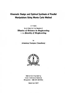
ject to the parameter synthesis are assumed to be the nominal parameters (Tab. 1). We consider the following requirements for the workspace of the manipulator. The size of the workspace is assumed to be 600 × 600 mm and the orientations of the platform should be such that it may be tilted by 30◦ in any direction. Further on, we want to limit the kinematic transmission between the platform and the drives to a factor of jmax = 4 which means that no drive should move faster than four times the translational velocity |w| ˙ of the platform. We apply the synthesis algorithm to the upper and lower leg length lu , ll , respectively, and to the radius rb of the machine’s frame. The solution set of the kinematically reachable workspace is depicted in Fig. 4a. Adding the restrictions from the dexterity requirements results in Fig. 4b. Comparing the results we can determine how the dexterity requirements restrict the solution set of the mechanism.
5.1. Computational Performance The interval evaluation of the system Φ is very fast since it is based on the compiled and optimized symbolic equations generated with computer algebra. Nevertheless, the computation of the solution set takes hundreds of millions function evaluations even for the case demonstrated here where we take into account three parameters. Basically, both memory and CPU usage increase exponentially with the number of parameters. The runtime for the presented example is about 90 s on a Pentium 4 with 3.2 GHz (MS Visual C++ 6). The calculation of the solution set with four parameters took about 12 hours on the same computer. Therefore, further optimizations on the algorithms and/or massive use of parallelization is needed to achieve parameter synthesis for all 8 independent design parameters.
6. CONCLUSIONS In this paper we demonstrated an approach to find an approximation of all feasible geometrical parameters of a PKM that fulfill a number of given process requirements. Clearly, the algorithm is very time consuming for higher dimensional parameter spaces but we want to emphasize two major advances of the method. First, we are able to find all solutions of the design problem. Second, the interval evaluation guarantees that the configurations found are valid with respect to the constraints we used due to the robust properties of interval analysis. In this paper we demonstrated the parameter synthesis for PKMs with constant leg length but we are positive that we can apply the algorithm for other types of PKMs by modifying the requirement constraints. In future works we will attempt to optimize the algorithms in order to reduce the computational costs. Further
4.5
4
4
3.5
3.5
rb [m]
rb [m]
4.5
3 2.5
3 2.5
2
2
1.5
1.5
1 0.5 5
1 5
0.5 5
4 4
3
3 2
1
ll [m]
2 0
1
5 4 4
3
3 2
1
ll [m]
lu [m]
a)
2 0
1
lu [m]
b)
Fig 4. Parameter synthesis for given workspace 600 × 600 mm with maximum tilt angle ϕmax = 30◦ for the parameters ll , lu , rb . a) without any dexterity restrictions b) max. transmission ratio jmax = 4 on, we are considering additional process requirements. Finally, we plan to choose the optimal machine from the solution set by minimizing the manufacturing costs of different designs.
[7]
ACKNOWLEDGMENTS
[8]
This work is supported by the German Research Council (Deutsche Forschungsgemeinschaft) under HI370/19-3.
[9]
References [1] D. Chablat, Ph. Wenger, F.Majou, and J. Merlet, An Interval Analysis Based Study for the Design and the Comparison of 3-DOF Parallel Kinematic Machines, International Journal of Robotics Research (2004). [2] D. Chablat, Ph. Wenger, and J. Merlet, Workspace Analysis of the Orthoglide Using Interval Analysis, Advances in Robot Kinematics (Dordrecht, Netherlands), Kluwer Academic Publishers, 2002, pp. 397–406. [3] F. Hao and J. Merlet, Multi-Criteria Optimal Design of Parallel Manipulators Based on Interval Analysis, Mechanism and Machine Theory 40 (2005), no. 2, 157–171. [4] A. M. Hay and J. A. Snyman, The Optimal Synthesis of Parallel Manipulators for Desired Workspaces, Advances in Robot Kinematics (Dordrecht, Netherlands), Kluwer Academic Publishers, 2002, pp. 337–346. [5] O. Kn¨uppel, PROFIL / BIAS – A Fast Interval Library, Computing 53 (1994), 277–287. [6] J. Merlet, Designing a Parallel Manipulator for a Spe-
[10]
[11] [12]
[13]
[14]
cific Workspace, Tech. Report 2527, Institut National de Recherche en Informatique et en Automatique (INRIA), Sophia-Antipolis Cedex (France), April 1995. , The Importance of Optimal Design for Parallel Structures, First European-American Forum on Parallel Kinematic Machines, 1998. , Parallel Robots, Solid Mechanics and its Application, Kluwer Academic Publishers, Dordrecht, 2000. , An Improved Design Algorithm Based on Interval Analysis for Spatial Parallel Manipulators with Specified Workspace, IEEE International Conference on Robotics and Automation (Seoul, Korea), 2001. , Guaranteed in-the-workspace Improved Trajectory/Surface/Volume Verification for Parallel Robots, IEEE International Conference on Robotics and Automation (New Orleans, USA), 2004. R. Moore, Interval Analysis, Prentice-Hall, Englewood Cliffs, New Jersey, 1966. A. Pott, D. Franitza, and M. Hiller, Orientation Workspace Verification for Parallel Kinematic Machines with Constant Leg Length, Proceedings of Mechatronics and Robotics 2004 (Aachen, Germany), 2004, pp. 984–989. G. Pritschow, C. Eppler, and T. Garber, Influence of the Dynamic Stiffness on the Accuracy of PKM, Proceedings of the 3th Chemnitz Parallel Kinematics Seminar (Chemnitz, Germany), 2002. F. Ranjbaran, J. Angeles, and A. Kecskem´ethy, On the Kinematic Conditioning of Robotic Manipulators, IEEE International Conference on Robotics and Automation (Minneapolis, Minnesota), 1996, pp. 3167–3172.


![[PDF] Download Machines Mechanisms: Applied Kinematic Analysis ...](https://m.moam.info/img/260x300/pdf-download-machines-mechanisms-applied-kinematic_6477b1d9097c4786708bfe90.jpg)