Hindawi Publishing Corporation Mathematical Problems in Engineering Volume 2015, Article ID 584954, 10 pages http://dx.doi.org/10.1155/2015/584954
Research Article Parametric Controller Design of Hopf Bifurcation System Jinbo Lu, Xiaorong Hou, and Min Luo School of Energy Science and Engineering, University of Electronic Science and Technology of China, Chengdu, Sichuan 611131, China Correspondence should be addressed to Xiaorong Hou;
[email protected] Received 11 September 2015; Accepted 17 December 2015 Academic Editor: Stefano Lenci Copyright © 2015 Jinbo Lu et al. This is an open access article distributed under the Creative Commons Attribution License, which permits unrestricted use, distribution, and reproduction in any medium, provided the original work is properly cited. A general parametric controller design method is proposed for Hopf bifurcation of nonlinear dynamic system. This method does not increase the dimension of the system. Compared with the existing methods, the controller designed by this method has a lower controller order and a simpler structure, and it does not contain equilibrium points. The method keeps equilibrium of the origin system unchanged. Symbolic computation is used to deduce the constraints of controller, and cylindrical algebraic decomposition is used to find the stability parameter regions in parameter space of controller. The method is then employed for Hopf bifurcation control. Taking Lorenz system as an example, the controller design steps of the method and numerical simulations are discussed. Computer simulation results are presented to confirm the analytical predictions.
1. Introduction Bifurcation is a normal phenomenon of nonlinear system, and the research in bifurcation control has achieved considerable progress in the past 30 years [1]. Hopf bifurcation is an important type of bifurcation. Its practical significance lies in the notion that Hopf bifurcation is a critical state between stable and unstable. There are a lot of related research achievements [2–4], covering a lot of fields, including power system [5, 6], electronic technology [7], network technology [8], new energy [9], and optical technology [10]. Hopf bifurcation research focused on phenomena analysis [11–13] and bifurcation control [14–19]. And the work of Hopf bifurcation control is designing control strategy for Hopf bifurcation system to modify the original system dynamic characteristics [16, 18, 20]. But the general applications of these designed controls are still limited. For enhancing flexibility and universality of Hopf bifurcation controller, some study of applying parametric control to Hopf bifurcation system controller design has emerged [17, 21]. On the basis of nonlinear state feedback theory, [17] gives a relatively common form of Hopf bifurcation control,
complete solution, and simulation of controller parameters by example. Its controller is 𝑢𝑞 (𝑋, 𝑋1∗ , 𝑋2∗ , . . . , 𝑋𝑘∗ , 𝜇) 𝑛
𝑘
𝑖=1
𝑗=1
= ∑𝐴 𝑞𝑖 ∏ (𝑥𝑖 − 𝑥𝑖𝑗∗ ) 𝑛
𝑘
𝑘
∗ + ∑ ∑ 𝐵𝑞𝑖𝑗 (𝑥𝑖 − 𝑥𝑖𝑗∗ ) ∏ (𝑥𝑖 − 𝑥𝑖𝑝 ) 𝑖=1 𝑗=1 𝑛
𝑘
+ ∑ ∑ 𝐶𝑞𝑖𝑗 (𝑥𝑖 − 𝑖=1 𝑗=1 𝑛
𝑘
𝑝=1
𝑘 2 𝑥𝑖𝑗∗ ) ∏ (𝑥𝑖 𝑝=1 2
𝑘
(1) ∗ − 𝑥𝑖𝑝 )
2
∗ + ∑ ∑ 𝐷𝑞𝑖𝑗 (𝑥𝑖 − 𝑥𝑖𝑗∗ ) ∏ (𝑥𝑖 − 𝑥𝑖𝑝 ) + ⋅⋅⋅ 𝑖=1 𝑗=1
𝑝=1
(𝑞 = 1, 2, . . . , 𝑛) ,
where 𝑋 is system state vector, 𝑋1∗ , 𝑋2∗ , . . . , 𝑋𝑘∗ are 𝑘 equilibrium points of system, 𝐴 𝑞𝑖 , 𝐵𝑞𝑖𝑗 , 𝐶𝑞𝑖𝑗 , and 𝐷𝑞𝑖𝑗 are the controller parameters, 𝑥𝑖 is 𝑖 state of system, and 𝑥𝑖𝑗∗ and
2
Mathematical Problems in Engineering
∗ 𝑥𝑖𝑝 are 𝑗 and 𝑝 equilibrium point value of system state 𝑥𝑖 , respectively. As can be seen from controller expression, the controller in [17] contains all of the system equilibrium points. The paper [21] has done a further study on the basis of [17]. The parameters of the controller have been simplified significantly, for a 3-dimensional system with two equilibrium points (the R¨ossler system). The controller in [21] is 3
𝑢3 = ∑ [𝐴 𝑖 (𝑥𝑖 − 𝑖=1
+ 𝑥𝑖0 ) (𝑥𝑖
−
− 𝑥𝑖0 )
(2)
2
+ − ) (𝑥𝑖 − 𝑥𝑖0 ) + 𝐵𝑖 (𝑥𝑖 − 𝑥𝑖0 2
+ − + 𝐵𝑖+3 (𝑥𝑖 − 𝑥𝑖0 ) (𝑥𝑖 − 𝑥𝑖0 ) ], + and where 𝐴 𝑖 , 𝐵𝑖 , and 𝐵𝑖+3 are the system parameters and 𝑥𝑖0 − 𝑥𝑖0 are the value of system state 𝑥𝑖 on the two equilibrium points. In addition to the controller design work, [21] used plane figure to display the controller constraints and analyzed the bifurcation cases of each connected region. Although the deep research of Hopf bifurcation control has been done in [17, 21], there are still some limitations. For example, the controller has a complicated form and higher order and includes system equilibrium points, and its parameters constraint solution is cumbersome. Besides, in [17], solution of controller parameters is not sufficient and intuitive. It just expresses several groups of controller parameters by inequality form. Except for the study of [17, 21], [22] did a further application in parametric method on the basis of [21]. In view of the above questions, in this paper, the controller form is improved, and a simple and general parametric controller design method is presented. The designed controller has lower order, and there is no inclusion of system equilibrium points. The remainder structure of this paper is as follows. Section 2 provides description of Hopf bifurcation system and the method and procedure of parametric controller design. Lorenz system is taken as an example in Section 3; this section designs the related parametric controller and deduces the constraints. In Section 4, numerical simulations are calculated. And in Section 5, the conclusion of this paper is given.
2. A Hopf Bifurcation System Description and Parametric Controller Design 2.1. Hopf Bifurcation System Description. Before discussing how to design a controller for Hopf bifurcation, a general formula of the Hopf bifurcation system is presented. To be more specific, consider the following general nonlinear system: 𝑇 𝑋̇ = 𝐹 (𝑋, 𝜇) = [𝑓1 (𝑋, 𝜇) , 𝑓2 (𝑋, 𝜇) , . . . , 𝑓𝑛 (𝑋, 𝜇)] , (3)
where the dot denotes differentiation with respect to time 𝑡 and 𝑋 = (𝑥1 , 𝑥2 , . . . , 𝑥𝑛 )𝑇 ∈ 𝑅𝑛 is an 𝑛-dimensional
state vector, while 𝜇 ∈ 𝑅 is a scalar parameter, called bifurcation parameter (note: it can be assumed that 𝜇 is an 𝑚-dimensional vector for 𝑚 ≥ 1). 𝐹(𝑋, 𝜇) is a matrix of nonlinear polynomial system with Hopf bifurcations, and the following conditions must be satisfied: (1) Let 𝑋∗ be an equilibrium (or fixed point) of the system; that is, 𝐹(𝑋∗ , 𝜇) ≡ 0, for any value of 𝜇. (2) Suppose that the Jacobian of the system evaluated at the equilibrium 𝑋∗ has eigenvalues, 𝜆 𝑗 (𝜇), 𝑗 = 1, 2, . . . , 𝑛, which may be real or complex. Assume there exists one pair of the complex conjugates 𝜆 1 (𝜇), 𝜆 2 (𝜇), and all of the others are in left half of complex plane. (3) Suppose that 𝜆 1,2 (𝜇) = 𝛼(𝜇) ± 𝑖𝛽(𝜇) cross the imaginary axis at 𝜇 = 𝜇∗ . When 𝜇 = 𝜇∗ , 𝛼(𝜇∗ ) = 0, 𝑑𝛼(𝜇∗ )/𝑑𝑡 ≠ 0, and 𝛽(𝜇∗ ) ≠ 0. According to the Hopf theory, a family of limit cycles will bifurcate from the equilibrium 𝑋∗ at the critical point 𝜇∗ . 2.2. Generic Parametric Controller Description. For system (3), we design a general formula of nonlinear state feedback control: 𝑋̇ = 𝐹 (𝑋, 𝜇) + 𝑢 (𝑋, 𝜇) ,
(4)
where 𝑇
𝑢 (𝑋, 𝜇) = [0, 0, . . . , 𝑢𝑗 (𝑋, 𝜇) , 0, . . . , 0] , 𝑛
𝑢𝑗 = 𝑔 (𝑋, 𝜇) 𝑓𝑗 (𝑋, 𝜇) + ∑ 𝑐0𝑖 𝑓𝑖 (𝑋, 𝜇) ;
(5)
𝑖=1, 𝑖=𝑗̸
here, 𝑛
𝑔 (𝑋, 𝜇) = 𝑐1 + ∑ (𝑐𝑘+1 𝑥𝑘 + 𝑐𝑛+𝑘+1 𝑥𝑘2 ) ,
(6)
𝑘=1
and {𝑐0𝑖 , 𝑐1 , 𝑐𝑘+1 , 𝑐𝑛+𝑘+1 ∈ 𝑅} are the parameters of controller. In the controller, the form of 𝑔(𝑋, 𝜇) is simple. 𝑔(𝑋, 𝜇) is the polynomial of system states and it is not including system equilibrium point (generally, the quadratic term is not needed). Comparing with [17], the designed controller is simpler and has lower order and is not including system equilibrium point. Under the control 𝑢, in order to keep all the original equilibria unchanged for controlled system (4), the following conditions must be satisfied: 𝑢 (𝑋∗ , 𝜇) = 0, 𝑢 (𝑋, 𝜇∗ ) ≠ 0.
(7)
Remark 1. The control equation given in (5) is not a unique control law. There are many other feasible controllers that may satisfy the system. In (5), the controller consists of system polynomial; 𝑐0𝑖 ∈ 𝑅 also can change for 𝑐0𝑖 ∈ 𝑅𝑛 . That is to say, 𝑐0𝑖 can be a one-dimensional parameter, which also can be a polynomial composed of system states. So on the premise of satisfying system requests, 𝑐0𝑖 has a variety of possible
Mathematical Problems in Engineering
3
expressions, covered by all linear combinations composed of system states, and then it includes the controller expression proposed by [17]. Remark 2. There may not be only one component in 𝑢(𝑋, 𝜇), but usually one component can satisfy the control system requests, so we only design one component here. Besides, as you can see, no matter how many components it has, there will be no inclusion of system equilibrium points value in controller 𝑢(𝑋, 𝜇). Remark 3. 𝑔(𝑋, 𝜇) form is not fixed. Higher polynomial can be introduced in it. Here, in order to reduce the controller order, 𝑔(𝑋, 𝜇), the highest order is 2, and in most cases, 1 order 𝑔(𝑋, 𝜇) is enough.
At this point, the Jacobian matrix of closed-loop system can be described as 𝜕𝑓1 [ 𝜕𝑥 [ 1 [ 𝐽 = [ 𝑗21 [ [ 𝜕𝑓3 [ 𝜕𝑥1
𝑥̇ 1 = 𝑓1 (𝑋, 𝜇) , 𝑥̇ 2 = 𝑓2 (𝑋, 𝜇) ,
(8)
Here, 𝑋 = [𝑥1 , 𝑥2 , 𝑥3 ]𝑇 . Then, system (8) has parametric controller: 𝑇
𝑢 (𝑋, 𝜇) = [𝑢1 (𝑋, 𝜇) , 𝑢2 (𝑋, 𝜇) , 𝑢3 (𝑋, 𝜇)] ,
(9)
𝑛
𝑢𝑗 (𝑋, 𝜇) = 𝑔 (𝑋, 𝜇) 𝑓𝑗 (𝑋, 𝜇) + ∑ 𝑐0𝑘 𝑓𝑘 (𝑋, 𝜇) ;
(10)
𝑘=1
here, {𝑢𝑗 (𝑋, 𝜇) ≠ 0, 𝑢𝑘 (𝑋, 𝜇) = 0, 𝑘 ≠ 𝑗, 𝑗 = 1, 2, 3}, 𝑔(𝑋) = 𝑐1 + 𝑐2 𝑥1 + 𝑐3 𝑥2 + 𝑐4 𝑥3 , {𝑐0𝑘 , 𝑐𝑖 ∈ 𝑅, 𝑖 = 1, 2, 3, 4}, and 𝑐0𝑘 and 𝑐𝑖 are controller parameters. In order to make concise expression, without loss of generality, controller (10) can be written as simplifying form: 𝑢2 (𝑋, 𝜇) = 𝑔 (𝑋, 𝜇) ⋅ 𝑓2 (𝑋, 𝜇) + 𝑐01 𝑓1 (𝑋, 𝜇) .
(11)
Step 2. According to the closed-loop system expression after adding controller, we can get Jacobian matrix including controller parameters. Adding controller (11) on system (8), closed-loop expression can be written as 𝑥̇ 1 = 𝑓1 (𝑋, 𝜇) ,
𝑥̇ 3 = 𝑓3 (𝑋, 𝜇) .
𝑗21 =
𝜕𝑓2 𝜕𝑓2 𝜕𝑓 + 𝑔 (𝑋) + 𝑐2 𝑓2 + 𝑐01 1 , 𝜕𝑥1 𝜕𝑥1 𝜕𝑥1
𝑗22 =
𝜕𝑓2 𝜕𝑓2 𝜕𝑓 + 𝑔 (𝑋) + 𝑐3 𝑓2 + 𝑐01 1 , 𝜕𝑥2 𝜕𝑥2 𝜕𝑥2
𝑗23 =
𝜕𝑓2 𝜕𝑓2 𝜕𝑓 + 𝑔 (𝑋) + 𝑐4 𝑓2 + 𝑐01 1 . 𝜕𝑥3 𝜕𝑥3 𝜕𝑥3
(14)
Step 3. In accordance with the gotten Jacobian matrix, we can compute system characteristic equation at the system equilibrium point. Supposing one equilibrium point of system (8) is 𝑋0 , then according to the Jacobian matrix, the characteristic equation at the system equilibrium point can be described as follows: 𝐷 (𝜆) = det (𝜆𝐼 − 𝐽)|𝑋=𝑋0 = 𝑎0 𝜆3 + 𝑎1 𝜆2 + 𝑎2 𝜆 + 𝑎3 ; (15)
𝑥̇ 3 = 𝑓3 (𝑋, 𝜇) .
𝑥̇ 2 = 𝑓2 (𝑋, 𝜇) + 𝑢2 (𝑋, 𝜇) ,
(13)
where
2.3. Parametric Controller Design Steps. For explaining parametric controller design method and steps, a 3-dimension system controller is designed as an example in this paper. The controller design steps are as follows. Step 1. According to the parametric controller equation, a 3dimension system with Hopf bifurcation is given:
𝜕𝑓1 𝜕𝑓1 𝜕𝑥2 𝜕𝑥3 ] ] 𝑗22 𝑗23 ] ], ] 𝜕𝑓3 𝜕𝑓3 ] 𝜕𝑥2 𝜕𝑥3 ]
here, 𝑎0 = 1, 𝑎1 = [−𝑐01 − 𝑐3 𝑓2 ] 𝑎2 = [(
𝑋=𝑋0
+ 𝑐01 ( −
,
𝜕𝑓1 𝜕𝑓2 𝜕𝑓1 𝜕𝑓2 𝜕𝑓2 𝜕𝑓3 𝜕𝑓2 𝜕𝑓3 − − + ) 𝜕𝑥1 𝜕𝑥2 𝜕𝑥2 𝜕𝑥1 𝜕𝑥3 𝜕𝑥2 𝜕𝑥2 𝜕𝑥3
⋅ 𝑔 (𝑋) − 𝑐2
𝜕𝑓 𝜕𝑓 𝜕𝑓1 𝜕𝑓 𝑓 −𝑐 3𝑓 +𝑐 𝑓 ( 3 + 1) 𝜕𝑥2 2 4 𝜕𝑥2 2 3 2 𝜕𝑥3 𝜕𝑥1
𝜕𝑓3 𝜕𝑓1 𝜕𝑓1 𝜕𝑓3 𝜕𝑓 𝜕𝑓 𝜕𝑓 𝜕𝑓 − )+ 1 2 + 1 3 𝜕𝑥3 𝜕𝑥2 𝜕𝑥3 𝜕𝑥2 𝜕𝑥1 𝜕𝑥2 𝜕𝑥1 𝜕𝑥3
𝜕𝑓1 𝜕𝑓2 𝜕𝑓1 𝜕𝑓3 𝜕𝑓2 𝜕𝑓3 𝜕𝑓2 𝜕𝑓3 − − + ] , 𝜕𝑥2 𝜕𝑥1 𝜕𝑥3 𝜕𝑥1 𝜕𝑥3 𝜕𝑥2 𝜕𝑥2 𝜕𝑥3 𝑋=𝑋0
𝑎3 = [(− −
(12)
𝜕𝑓 𝜕𝑓1 𝜕𝑓1 𝜕𝑓2 − − 𝑔 (𝑋) − 3 𝜕𝑥2 𝜕𝑥1 𝜕𝑥2 𝜕𝑥3
𝜕𝑓1 𝜕𝑓2 𝜕𝑓3 𝜕𝑓1 𝜕𝑓2 𝜕𝑓3 𝜕𝑓1 𝜕𝑓2 𝜕𝑓3 + + 𝜕𝑥1 𝜕𝑥2 𝜕𝑥3 𝜕𝑥1 𝜕𝑥3 𝜕𝑥2 𝜕𝑥2 𝜕𝑥1 𝜕𝑥3
𝜕𝑓1 𝜕𝑓2 𝜕𝑓3 𝜕𝑓1 𝜕𝑓2 𝜕𝑓3 𝜕𝑓1 𝜕𝑓2 𝜕𝑓3 − + ) 𝜕𝑥2 𝜕𝑥3 𝜕𝑥1 𝜕𝑥3 𝜕𝑥1 𝜕𝑥2 𝜕𝑥3 𝜕𝑥2 𝜕𝑥1
⋅ 𝑔 (𝑋) + (−𝑐3
𝜕𝑓1 𝜕𝑓3 𝜕𝑓 𝜕𝑓 𝜕𝑓 𝜕𝑓 + 𝑐4 1 3 − 𝑐4 1 3 𝜕𝑥1 𝜕𝑥3 𝜕𝑥1 𝜕𝑥2 𝜕𝑥2 𝜕𝑥1
4
Mathematical Problems in Engineering + 𝑐2
𝜕𝑓 𝜕𝑓1 𝜕𝑓3 𝜕𝑓 𝜕𝑓 𝜕𝑓 𝜕𝑓 + 𝑐3 1 3 − 𝑐2 1 3 ) 𝑓2 − 1 𝜕𝑥2 𝜕𝑥3 𝜕𝑥3 𝜕𝑥1 𝜕𝑥3 𝜕𝑥2 𝜕𝑥1
⋅
𝜕𝑓2 𝜕𝑓3 𝜕𝑓1 𝜕𝑓2 𝜕𝑓3 𝜕𝑓1 𝜕𝑓2 𝜕𝑓3 𝜕𝑓1 + + − 𝜕𝑥2 𝜕𝑥3 𝜕𝑥1 𝜕𝑥3 𝜕𝑥2 𝜕𝑥2 𝜕𝑥1 𝜕𝑥3 𝜕𝑥2
⋅
𝜕𝑓2 𝜕𝑓3 𝜕𝑓1 𝜕𝑓2 𝜕𝑓3 𝜕𝑓1 𝜕𝑓2 𝜕𝑓3 − + ] . 𝜕𝑥3 𝜕𝑥1 𝜕𝑥3 𝜕𝑥1 𝜕𝑥2 𝜕𝑥3 𝜕𝑥2 𝜕𝑥1 𝑋=𝑋0
Remark 5. In constraints 𝑙4 , when 𝑙4 = 0, Hopf bifurcation occurs, at which the system is critically stable, and its state characteristic is continuous oscillation. If 𝑙4 > 0, the system is stable and the state is convergent.
3. Lorenz System Controller Design (16)
Remark 4. 𝑋0 does not require the actual solution. It is only a formal symbol. You can see the specific condition in the subsequent computation example; 𝑋0 in Step 4 is the same as here. Step 4. Using Hurwitz criterion, we can get the stable constraint of system and simplify it by polynomial division. According to Hurwitz criterion, the constraints including controller parameter are 𝑎0 > 0,
(17)
𝑎3 > 0, 𝑔 = 𝑎1 𝑎2 − 𝑎0 𝑎3 ≥ 0. Considering 𝑎0 = 1, the system stable constraints can be written as 𝑎1 > 0, 𝑎2 > 0, 𝑎3 > 0,
(18)
𝑥̇ = −𝑎 (𝑥 − 𝑦) , 𝑦̇ = 𝑏𝑥 − 𝑥𝑧 − 𝑦,
(21)
in which 𝑎, 𝑏, and 𝑐 are variable parameters. These parameters have direct effect on system characteristics. A little change of them may change the system state and make system trajectory turn from stable to bifurcation and even chaos [17]. According to (21), we can obtain system equilibrium point equation: 𝑥03 − (𝑏𝑐 − 𝑐) 𝑥0 = 0.
In accordance with polynomial division, for 𝑘 order real polynomial 𝐵(𝑋) and 𝑚 order real polynomial 𝐴(𝑋), 𝑋 ∈ 𝑅𝑛 , 𝑘 ≥ 1, 𝑚 ≥ 1, 𝐴(𝑋) can be written as (19)
here, 𝐴(𝑋) is the integral part of 𝐴(𝑋) divided by 𝐵(𝑋) and 𝐿 𝐴/𝐵 (𝑋) is the residue of 𝐴(𝑋) divided by 𝐵(𝑋). If 𝐵(𝑋0 ) = 0 at 𝑋0 , then 𝐿 𝐴/𝐵 (𝑋0 ) = 𝐴(𝑋0 ). Supposing 𝐺(𝑋) = 0 is system (8) equilibrium point equation and 𝑋0 is the equilibrium, then the system constraints can be simplified as 𝑙1 = 𝐿 𝑎1 /𝐺 (𝑋0 ) > 0 { { { { { { {𝑙2 = 𝐿 𝑎2 /𝐺 (𝑋0 ) > 0 𝑆:{ (20) { { 𝑙3 = 𝐿 𝑎3 /𝐺 (𝑋0 ) > 0 { { { { {𝑙4 = 𝐿 𝑔/𝐺 (𝑋0 ) > 0. Step 5. Using computer algebra tools such as symbol computation software and cylindrical algebraic decomposition algorithm to solve semialgebraic set composed of (20) and equilibrium point equation 𝐺(𝑋) = 0, we can get controller parameter space satisfying system requests.
(22)
3.2. Controller Design. In accordance with (11), controller can be designed as 𝑢2 = 𝑦̇ (𝑐1 + 𝑐2 𝑥 + 𝑐3 𝑦 + 𝑐4 𝑧) + 𝑐0 𝑥,̇
𝑔 = 𝑎1 𝑎2 − 𝑎3 ≥ 0.
𝐴 (𝑋) = 𝐴 (𝑋) 𝐵 (𝑋) + 𝐿 𝐴/𝐵 (𝑋) ;
3.1. Lorenz System Description. According to [17], Lorenz system can be described as
𝑧̇ = 𝑥𝑦 − 𝑐𝑧,
𝑎1 > 0, 𝑎2 > 0,
It is well known that the Lorenz system widely exists in various research areas [23–26] and it can exhibit complex dynamics, including equilibria, limit cycles, and chaos. This section will explain the controller design and verification process by Lorenz system.
(23)
where 𝑐0 ∈ 𝑅, 𝑐1 ∈ 𝑅, 𝑐2 ∈ 𝑅, 𝑐3 ∈ 𝑅, and 𝑐4 ∈ 𝑅 are controller parameters. According to (21), controller can be rewritten as 𝑢2 = (𝑏𝑥 − 𝑥𝑧 − 𝑦) (𝑐1 + 𝑐2 𝑥 + 𝑐3 𝑦 + 𝑐4 𝑧) − 𝑐0 𝑎 (𝑥 − 𝑦) .
(24)
Compared with the existing research work [17, 21], (24) has a more concise expression, and it does not include equilibrium point value. 3.3. System Stable and Hopf Bifurcation Condition Computation. Lorenz system state characteristics will be directly affected by system parameters. In order to verify controller performance, we select system parameters 𝑎 = 4, 𝑏 = 16, and 𝑐 = 1. When there is no controller, system state trajectory is chaotic. Taking system parameters in Lorenz system (21), we can obtain a new system: 𝑥̇ = −4 (𝑥 − 𝑦) , 𝑦̇ = 16𝑥 − 𝑥𝑧 − 𝑦, 𝑧̇ = 𝑥𝑦 − 𝑧.
(25)
Mathematical Problems in Engineering
5 0.5
In accordance with (25), the equation at system equilibrium point is 𝑥03 − 15𝑥0 = 0.
𝑢2 (𝑥, 𝑦, 𝑧) = 𝑦̇ (𝑐1 + 𝑐2 𝑥 + 𝑐4 𝑧) .
c4
0.2 0 −0.2
Taking in (27), after computation and arrangement, we can get system constraints: (28)
𝑙2 = (5 + 5𝑐1 + 16𝑐4 ) 𝑥02 + 16𝑐2 𝑥0 − 59𝑐1 − 55,
(29)
𝑙3 = (120𝑐4 + 12𝑐1 + 12) 𝑥02 + 120𝑐2 𝑥0 − 60𝑐1 − 60,
(30)
𝑙4 = (5𝑐12 + 16𝑐22 + 240𝑐42 + 32𝑐1 𝑐4 + 23𝑐1 − 4𝑐4 + 18) 𝑥02 + (32𝑐1 𝑐2 + 480𝑐2 𝑐4 − 4𝑐2 ) 𝑥0 −
59𝑐12
(31)
−1
−0.8 −0.6 −0.4 −0.2
𝑐4 >
0.8
1
375 39 𝑐 + > 0, 4 4 4
(34)
𝜑 = (5𝑐22 − 75𝑐42 + 30𝑐4 − 3) ⋅ (240𝑐22 − 3600𝑐42 + 1560𝑐4 − 169) ≥ 0.
𝑐1 + 15𝑐4 + 1 > 0, 2
(32)
2
1 1 15𝑐22 + (𝑐1 + 15𝑐4 − ) − > 0, 8 64
as
When 𝑐1 = −5, system constraints (32) can be rewritten 𝑐4 >
4 , 15
− 15𝑐22 + 225𝑐42 − 120𝑐4 + 16 > 0,
𝜑 ≥ 0,
15𝑐22 + 225𝑐42 −
where
+ 480𝑐1 𝑐4 − 120𝑐4 − 8𝑐1 + 1) .
0.6
2 , 15
15𝑐22 + 225𝑐42 −
−5 ≤ 𝑐1 < −1,
+
0.4
− 15𝑐22 + 225𝑐42 − 60𝑐4 + 4 > 0,
Combined with (26) at equilibrium point, constraints equations (28)∼(31) constitute a semialgebra set. Using computer algebra tools, we can simplify the semialgebra set. The arranged system constraints are as follows:
3600𝑐42
0.2
the system has a bifurcation when 𝑐1 = −5, we can choose two different conditions 𝑐1 = −3 and 𝑐1 = −5 for analysis in numerical simulation. When 𝑐1 = −3, Lorenz system constraints (32) can be rewritten as
− 270.
𝜑 = (𝑐12 − 15𝑐22 + 255𝑐42 + 30𝑐1 𝑐4 ) (16𝑐12 − 240𝑐22
0 c2
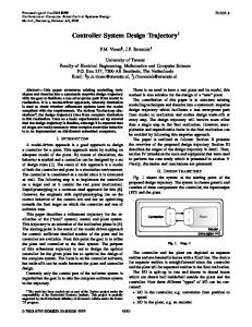
Figure 1: System constraints curves in 𝑐2 -𝑐4 plane when 𝑐0 = 0 and 𝑐1 = −3.
− 349𝑐1
−15𝑐22 + (𝑐1 + 15𝑐4 + 1) > 0,
0.1 −0.1
(27)
𝑙1 = 𝑐4 𝑥02 + 𝑐2 𝑥0 + 𝑐1 + 6,
L2 Qs
0.3
(26)
For simplifying computation process, let 𝑐0 = 0, 𝑐3 = 0, and the controller can be simplified as
L1
0.4
(33)
In (32), if 𝑐1 = −5 or 𝜑 = 0, the Hopf bifurcation will happen in system. The constraints listed in (32) can use cylindrical algebraic decomposition algorithm to calculate the controller parameter space. But the 3-dimension decomposition result is still not intuitive. In the following numerical simulation, we will assign a certain value to 𝑐1 and then mark out the controller parameter range in 2-dimension space.
4. Simulations 4.1. Constraints Calculation. Through the above analysis results, we can see 𝑐1 ∈ [−5, −1). If the system is required to be stable, parameter 𝑐1 should satisfy 𝑐1 ∈ (−5, −1). Because
615 105 𝑐 + > 0, 4 4 4
(35)
𝜑 = (−3𝑐22 + 45𝑐42 − 30𝑐4 + 5) ⋅ (−80𝑐22 + 1200𝑐42 − 840𝑐4 + 147) ≥ 0. 4.2. Controller Parameter Region. As shown in Figure 1, implicit function curves of constraints (34) equations are drawn in the 2-dimension space. According to cylindrical algebraic decomposition algorithm, we can search the space divided by these function curves; then region 𝑄𝑠 is found. In the region, 𝑐2 and 𝑐4 can stabilize system. The boundary curves of 𝑄𝑠 are 𝐿 1 and 𝐿 2 , and 𝐿 1 and 𝐿 2 are part of 𝜑 = 0 in (34). 𝐿 1 is line 60𝑐2 + 60√15𝑐4 − 13√15 = 0 when 𝑐2 ≤ 0; 𝐿 2 is line −60𝑐2 + 60√15𝑐4 − 13√15 = 0 when 𝑐2 ≥ 0. In order to provide a convenient explanation, we suppose the three equilibrium points of (26) are 𝐸0 , 𝐸− , and 𝐸+ , where 𝐸− and 𝐸+ are a pair of symmetric equilibrium points. For
6
Mathematical Problems in Engineering 0.7 0.6
0
L3
L4
−0.2
c4
0.5 z
Qh
0.4
−0.4 −0.6 −0.8
0.3
−1 2
0.2
1 y
0.1 −1
−0.5
0 c2
0.5
0 −1 −0.4
1
−0.2
0 x
0.2
0.4
Figure 3: The Lorenz system trajectory is stable at 𝐸0 when 𝑐1 = −3.
Figure 2: System constraints curves in 𝑐2 -𝑐4 plane when 𝑐0 = 0 and 𝑐1 = −5.
16
parameter space solved by constraints (34), the system state at 𝐸0 is convergent. Choosing different parameters can decide whether there is a bifurcation at system equilibrium points 𝐸− and 𝐸+ : (i) there is no existing Hopf bifurcation at two equilibrium points, while the system states are stable, and at the moment the controller parameters 𝑐2 and 𝑐4 value should be in 𝑄𝑠 but not on the boundary; (ii) system states are stable at equilibrium point 𝐸− while at 𝐸+ there is a Hopf bifurcation, and at the moment controller parameter value should on the boundary 𝐿 1 ; (iii) there is a Hopf bifurcation at equilibrium point 𝐸− while system is stable at 𝐸+ , and at the moment controller parameter should be on the boundary 𝐿 2 ; (iv) there are Hopf bifurcations at both equilibrium points, and at the moment controller parameter should be on the cross point of 𝐿 1 and 𝐿 2 . The implicit function curves of constraints (35) equations are shown in Figure 2. Similar to constraints (34), using cylindrical algebraic decomposition algorithm, we can find the parameter space 𝑄ℎ which satisfies the control requirements. The boundaries of region 𝑄ℎ are lines 𝐿 3 and 𝐿 4 . They are part of 𝜑 = 0 in (35). 𝐿 3 is line 20𝑐2 + 20√15𝑐4 − 7√15 = 0 when 𝑐2 ≤ 0, and 𝐿 4 is line −20𝑐2 + 20√15𝑐4 − 7√15 = 0 when 𝑐2 ≥ 0. Unlike constraints (34), there is a Hopf bifurcation at 𝐸0 in (26) by this time. According to the different states at equilibrium points 𝐸− and 𝐸+ , the cases are as follows: (i) both equilibria become stable without Hopf bifurcations; at the moment, the controller parameters 𝑐2 and 𝑐4 value should be selected in 𝑄ℎ and should not be on the boundary; (ii) the system states are stable at equilibrium point 𝐸− , while there is a Hopf bifurcation at 𝐸+ , and at the moment controller parameter value should on the boundary 𝐿 3 ; (iii) there is a Hopf bifurcation at equilibrium point 𝐸− , while at 𝐸+ , system is stable, and at the moment controller parameter should be on the boundary 𝐿 4 ; (iv) there are Hopf bifurcations at both equilibrium points, and at the moment controller parameter should be on the cross point of 𝐿 3 and 𝐿 4 .
15.5 z
15 14.5 14 0 −2 y
−3.5
−4 −6 −4.5
−4
−3
x
Figure 4: Stable trajectory at 𝐸− , when 𝑐1 = −3, for case (i).
4.3. Numeric Simulation Computation Near Equilibria. According to the different conditions at three equilibrium points, we compute the controller parameters below. In order to explain the validity of solved controller parameter range, we conduct the numeric simulation of state stability near equilibrium points for Lorenz system (25). The simulation results are shown in Figures 3–20. When simulating, the initial values of system equilibrium points 𝐸0 , 𝐸− , and 𝐸+ are (0, 1, −1), (−4, −4, 16), and (4, 4, 16). When controller parameter 𝑐1 = −3, the system trajectory at 𝐸0 is convergent, while according to the different cases of 𝐸− and 𝐸+ , parameters 𝑐2 and 𝑐4 can be selected as follows: (i) when the system is stable at two equilibrium points, we can select 𝑐2 = 1, 𝑐4 = 1; (ii) system is stable at equilibrium point 𝐸− , while at 𝐸+ it has a Hopf bifurcation, and at the moment we can select 𝑐2 = −1, 𝑐4 = (1/60)(13 + 4√15) ≈ 0.47487; (iii) there is a Hopf bifurcation at equilibrium point 𝐸− , while system is stable at 𝐸+ , and at the moment we can select 𝑐2 = 1, 𝑐4 = (1/60)(13+4√15) ≈ 0.47487; (iv) both equilibria 𝐸− and 𝐸+ have Hopf bifurcations, and at the moment we can select 𝑐2 = 0, 𝑐4 = 13/60 ≈ 0.21667.
Mathematical Problems in Engineering
7
16 z
15.5 z
15
16 15.8 15.6 15.4 15.2 15 14.8 14.6 14.4 14.2 14 −2.5
14.5 14 6
4.5 4
2
3.5
0 3
z
16 15.5
−3 y
−4
−3
5 4.5
4 3.5 y
3 2.5
2 3
3.5
4.5
4 x
−5
−4
−6 −4.5
16
−3
−3.5 x
15.5 z
Figure 6: Stable trajectory at 𝐸− , when 𝑐1 = −3, for case (ii).
16 15.8 15.6 15.4 15.2 15 14.8 14.6 14.4 14.2 14 5
−3.4−3.2 −3.8 −3.6 −4 −4.5 −5 −4.4 −4.2 x
Figure 9: Stable trajectory at 𝐸+ , when 𝑐1 = −3, for case (iii).
14.5
z
16 15.8 15.6 15.4 15.2 15 14.8 14.6 14.4 14.2 5.5
15
14 −2
−4
x
Figure 5: Stable trajectory at 𝐸+ , when 𝑐1 = −3, for case (i).
z
−3.5 y
Figure 8: Hopf bifurcation at 𝐸− , when 𝑐1 = −3, for case (iii).
4 y
−3
15 14.5 14 13.5 −3
−3.4 −3.8 −4.2 y −4.6
−3.8 −5 −4.6 −4.4 −4.2 −4 x
−3.6 −3.4
−3.2 −3
Figure 10: Hopf bifurcation at 𝐸− , when 𝑐1 = −3, for case (iv).
4.5
4
y
3.5
3
2.5 3.2
4 3.8 3.6 x 3.4
4.6 4.4 4.2
Figure 7: Hopf bifurcation at 𝐸+ , when 𝑐1 = −3, for case (ii).
In Figure 3 the Lorenz system trajectory is convergent at 𝐸0 when 𝑐1 = −3. Figures 4–11 are system simulation trajectories for different cases of 𝐸− and 𝐸+ , in which, corresponding to case (i), Figure 4 is the stable convergent trajectory at 𝐸− , and Figure 5 is the stable convergent trajectory at 𝐸+ . Corresponding to case (ii), Figure 6 is the stable convergent trajectory at 𝐸− , and Figure 7 is the system
trajectory of Hopf bifurcation at 𝐸+ . For case (iii), Figure 8 is the Hopf bifurcation trajectory at 𝐸− , and Figure 9 is the stable convergent trajectory at 𝐸+ . Figures 10 and 11 are the system trajectories of Hopf bifurcation at 𝐸− and 𝐸+ for case (iv). When controller parameter 𝑐1 = −5, system has Hopf bifurcation at 𝐸0 , and its trajectory is a limit cycle. And according to different cases at 𝐸− and 𝐸+ , parameters 𝑐2 and 𝑐4 can be chosen as follows: (i) when the system is stable at two equilibrium points, we can select 𝑐2 = 1, 𝑐4 = 1; (ii) system is stable at equilibrium point 𝐸− , while there is a Hopf bifurcation at 𝐸+ , and at the moment we can select 𝑐2 = −1, 𝑐4 = (1/60)(21 + 4√15) ≈ 0.60819; (iii) there is a Hopf bifurcation at equilibrium point 𝐸− , while system is stable at 𝐸+ , and at the moment we can select 𝑐2 = 1, 𝑐4 = (1/60)(21 +4√15) ≈ 0.60819; (iv) there are Hopf bifurcations at both equilibria, and we can select 𝑐2 = 0, 𝑐4 = 7/20 = 0.35.
8
Mathematical Problems in Engineering
16 15.5 z
15
z
14.5 14 13.5 4.8 4.6 4.4
4.2 4 3.83.6 y 3.4
3.8 4 3.2 3 3.2 3.4 3.6 x
4.6 4.8 4.2 4.4
z
z
1
0.5 y
0
−0.5
0.3 0.4 0.1 0.2 0 −0.2−0.1 −1 x −1.5−0.4 −0.3
z
z
−5.5 −4.5
−4
−3
−3.5
−4
x
16 15.5 15 14.5 14 13.5 5
4.5
4 y
3.5
3
2.5 3.2
4.2 3.8 4 3.6 x 3.4
4.4 4.6
Figure 16: Hopf bifurcation at 𝐸+ , when 𝑐1 = −5, for case (ii).
Figure 12: System Hopf bifurcation trajectory at 𝐸0 when 𝑐1 = −5.
16 15.8 15.6 15.4 15.2 15 14.8 14.6 14.4 14.2 −2 −2.5 −3 −3.5 −4 −4.5 −5 y
−5.5 −4.5
−3
−3.5
Figure 15: Stable trajectory at 𝐸− , when 𝑐1 = −5, for case (ii).
Figure 11: Hopf bifurcation at 𝐸+ , when 𝑐1 = −3, for case (iv).
0.4 0.2 0 −0.2 −0.4 −0.6 −0.8 −1 1.5
16 15.8 15.6 15.4 15.2 15 14.8 14.6 14.4 14.2 −2 −2.5 −3 −3.5 −4 y −4.5 −5
x
16 15.5 15 14.5 14 13.5 −2.5
−3
−3.5 −4 y −4.5
Figure 13: Stable trajectory at 𝐸− , when 𝑐1 = −5, for case (i).
−3.8 −3.6 −5 −4.4 −4.2 −4 x
−3.4 −3.2
−3
Figure 17: Hopf bifurcation at 𝐸− , when 𝑐1 = −5, for case (iii).
z
16 15.8 15.6 15.4 15.2 15 14.8 14.6 14.4 5.5
5 4.5
4 3.5 y
3 2.5
3.2 2 1.5 3
3.8 3.6 3.4 x
4
4.2
4.4
Figure 14: Stable trajectory at 𝐸+ , when 𝑐1 = −5, for case (i).
z
16 15.8 15.6 15.4 15.2 15 14.8 14.6 14.4 14.2 5.5
5 4.5
4 3.5 y
3 2.5
2 3
3.5
4
4.5
x
Figure 18: Stable trajectory at 𝐸+ , when 𝑐1 = −5, for case (iii).
Figure 12 is the system Hopf bifurcation trajectory at 𝐸0 when 𝑐1 = −5, and at this moment system converges to a stable limit cycle. Figures 13–20 are system simulation trajectories at 𝐸− and 𝐸+ for different cases, in which,
according to case (i), Figures 13 and 14 are the stable trajectories at 𝐸− and 𝐸+ . In accordance with case (ii), Figure 15
Mathematical Problems in Engineering
z
16 15.5 15 14.5 14 13.5 −3
9
16.2 16.1 z −3.4
−3.8 −4.2 y −4.6
−3.2 −3.6 −3.4 −4 −3.8 −5 −4.4 −4.2 x
−3
Figure 19: Hopf bifurcation at 𝐸− , when 𝑐1 = −5, for case (iv).
16 15.9 15.8 4 3.9 y
3.8 3.7
15.5
4
x
Figure 22: Stable at 𝐸+ using controllers in [17] and this paper.
15 14.5 14 13.5 4.8 4.6
4.4 4.2 y
4 3.8 3.63.4
3.2 3 3.2
3.8 4 3.4 3.6 x
4.2
4.4 4.6
16.2 16.1 16 15.9 15.8 −3.7 −3.8
y
−3.9 −4 −4
−3.95
−3.9
x
−3.85
see that both controllers can stabilize the Lorenz system at equilibrium, and the controller designed in this paper is more simple and practical.
5. Conclusions
Figure 20: Hopf bifurcation at 𝐸+ , when 𝑐1 = −5, for case (iv).
z
3.85
3.95
1 2
16
z
3.8
3.9
−3.8
−3.75
1 2
Figure 21: Stable at 𝐸− using controllers in [17] and this paper.
Aiming at the limitations of existing controller such as complex controller form, high order, including system equilibrium points in controller, and complicated solving method for parameters constraints, in this paper, a new parametric controller design method is proposed by researching and analyzing present Hopf bifurcation nonlinear system parametric controller design methods. This paper presents the design principle analysis and computation steps of this new parametric controller, designs a corresponding parametric controller for a Lorenz system example, deduces the constraints, and explains the controller method validity by numeric simulation. From simulation, compared with the other methods, it is easy to see that this new parametric controller method has simple form, lower order, not including any equilibrium point value.
Conflict of Interests The authors declare that there is no conflict of interests regarding the publication of this paper.
Acknowledgment is the stable trajectory at 𝐸− , and Figure 16 is the Hopf bifurcation trajectory at 𝐸+ . For case (iii), Figure 17 is the Hopf bifurcation trajectory at 𝐸− , and Figure 18 is the stable trajectory at 𝐸+ . In accordance with condition (iv), Figure 19 is the Hopf bifurcation trajectory at 𝐸− , and Figure 20 is the Hopf bifurcation trajectory at 𝐸+ . Figures 21 and 22 are the system stable trajectories, using the controllers of this paper and [17]. Curve 1 is the system trajectory under the control of [17] and curve 2 is under the control of this paper. From Figures 21 and 22, it is easy to
This work is partially supported by the NSF of China Grants nos. 61374001 and 61074189.
References [1] E. H. Abed and J.-H. Fu, “Local feedback stabilization and bifurcation control. I. Hopf bifurcation,” Systems & Control Letters, vol. 7, no. 1, pp. 11–17, 1986. [2] G. Chen and K. Yap, “Feedback control of Hopf bifurcations,” IEEE Transactions on Circuits and Systems I: Fundamental Theory and Applications, vol. 6, pp. 661–672, 2001.
10 [3] A. Jimenez-Triana, W. K.-S. Tang, G. Chen, and A. Gauthier, “Chaos control in duffing system using impulsive parametric perturbations,” IEEE Transactions on Circuits and Systems, vol. 57, no. 4, pp. 305–309, 2010. [4] C. Bi, Y. Xiang, Q. Zhang, and J. Hu, “Simulation study of bifurcation control in synchronous switching converter,” in Proceedings of the International Conference on Communications, Circuits and Systems (ICCCAS ’13), vol. 2, pp. 463–466, Chengdu, China, November 2013. [5] A. R. Phadke, M. Fozdar, K. R. Niazi, N. Mithulananthan, and R. C. Bansal, “New technique for computation of closest Hopf bifurcation point using real-coded genetic algorithm,” IET Generation, Transmission & Distribution, vol. 5, no. 1, pp. 11–18, 2011. [6] M. Tomim, B. Lopes, R. Leme et al., “Modified Hopf bifurcation index for power system stability assessment,” IEE Proceedings— Generation, Transmission and Distribution, vol. 152, no. 6, pp. 906–912, 2005. [7] A. Kavitha and G. Uma, “Experimental verification of Hopf bifurcation in DC–DC Luo converter,” IEEE Transactions on Power Electronics, vol. 23, no. 6, pp. 2878–2883, 2008. [8] F. Liu, H. O. Wang, and Z.-H. Guan, “Stability analysis and control of bifurcation in a TCP fluid flow model of wireless networks,” in Proceedings of the 10th World Congress on Intelligent Control and Automation (WCICA ’12), pp. 1026–1030, IEEE, Beijing, China, July 2012. [9] L. Yang, Z. Xu, J. Østergaard, Z. Y. Dong, K. P. Wong, and X. Ma, “Oscillatory stability and eigenvalue sensitivity analysis of a DFIG wind turbine system,” IEEE Transactions on Energy Conversion, vol. 26, no. 1, pp. 328–339, 2011. [10] K. E. Chlouverakis, K. M. Al-Aswad, I. D. Henning, and M. J. Adams, “Determining laser linewidth parameter from Hopf bifurcation minimum in lasers subject to optical injection,” Electronics Letters, vol. 39, no. 16, pp. 1185–1187, 2003. [11] M. Huang, C. K. Tse, S.-C. Wong, C. Wan, and X. Ruan, “Lowfrequency hopf bifurcation and its effects on stability margin in three-phase PFC power supplies connected to non-ideal power grid,” IEEE Transactions on Circuits and Systems I: Regular Papers, vol. 60, no. 12, pp. 3328–3340, 2013. [12] P. S. Deivasundari, G. Uma, and R. Santhi, “Experimental verification of Hopf bifurcation in pulse-width modulated inverter fed cage induction motor drive system,” IET Power Electronics, vol. 7, no. 2, pp. 340–349, 2014. [13] N. G. Sakellaridis, M. E. Karystianos, and C. D. Vournas, “Homoclinic loop and degenerate hopf bifurcations introduced by load dynamics,” IEEE Transactions on Power Systems, vol. 24, no. 4, pp. 1892–1893, 2009. [14] G. Chen, J. L. Moiola, and H. O. Wang, “Bifurcation control: theories, methods, and applications,” International Journal of Bifurcation and Chaos, vol. 10, no. 3, pp. 511–548, 2000. [15] F. Liu, G. Xiong, Z.-H. Guan, and H. O. Wang, “Stability analysis and control Hopf bifurcation in a FAST TCP model,” in Proceedings of the 32nd Chinese Control Conference (CCC ’13), pp. 1076–1080, Xi’an, China, July 2013. [16] M. Xiao, W. X. Zheng, and J. Cao, “Hopf bifurcation of an (n + 1)-neuron bidirectional associative memory neural network model with delays,” IEEE Transactions on Neural Networks and Learning Systems, vol. 24, no. 1, pp. 118–132, 2013. [17] P. Yu and G. Chen, “Hopf bifurcation control using nonlinear feedback with polynomial functions,” International Journal of Bifurcation and Chaos in Applied Sciences and Engineering, vol. 14, no. 5, pp. 1683–1704, 2004.
Mathematical Problems in Engineering [18] T. Yang and X. Chen, “Local L2 gain of Hopf bifurcation stabilization,” in Proceedings of the 47th IEEE Conference on Decision and Control (CDC ’08), pp. 4103–4108, IEEE, Canc´un, Mexico, December 2008. [19] P. Cai, J.-S. Tang, and Z.-B. Li, “Controlling Hopf bifurcation of a new modified hyperchaotic L¨u system,” Mathematical Problems in Engineering, vol. 2015, Article ID 614135, 6 pages, 2015. [20] F. Verduzco, J. Alvarez, and A. Carrillo, “Normal form and control of the Hopf bifurcation,” in Proceedings of the American Control Conference (ACC ’07), pp. 2358–2363, New York, NY, USA, July 2007. [21] Z. Wu and P. Yu, “A method for stability and bifurcation control,” IEEE Transactions on Automatic Control, vol. 51, no. 6, pp. 1019–1023, 2006. [22] Z.-Q. Wu, R. Ding, and Y.-S. Chen, “Classification of parametrically constrained bifurcations,” Applied Mathematics and Mechanics. English Edition, vol. 31, no. 2, pp. 135–142, 2010. [23] K. Cho and T. Miyano, “Chaotic cryptography using augmented lorenz equations aided by quantum key distribution,” IEEE Transactions on Circuits and Systems I: Regular Papers, vol. 62, no. 2, pp. 478–487, 2015. [24] R. Tokunaga, T. Matsumoto, L. O. Chua, and S. Miyama, “The piecewise-linear Lorenz circuit is chaotic in the sense of Shilnikov,” IEEE Transactions on Circuits and Systems, vol. 37, no. 6, pp. 766–786, 1990. [25] S. Yu, J. Lu, X. Yu, and G. Chen, “Design and implementation of grid multiwing hyperchaotic Lorenz system family via switching control and constructing super-heteroclinic loops,” IEEE Transactions on Circuits and Systems, vol. 59, no. 5, pp. 1015–1028, 2012. [26] A. Dwivedi, A. K. Mittal, and S. Dwivedi, “Adaptive synchronisation of diffusionless Lorenz systems and secure communication of digital signals by parameter modulation,” IET Communications, vol. 6, no. 13, pp. 2016–2026, 2012.
Advances in
Operations Research Hindawi Publishing Corporation http://www.hindawi.com
Volume 2014
Advances in
Decision Sciences Hindawi Publishing Corporation http://www.hindawi.com
Volume 2014
Journal of
Applied Mathematics
Algebra
Hindawi Publishing Corporation http://www.hindawi.com
Hindawi Publishing Corporation http://www.hindawi.com
Volume 2014
Journal of
Probability and Statistics Volume 2014
The Scientific World Journal Hindawi Publishing Corporation http://www.hindawi.com
Hindawi Publishing Corporation http://www.hindawi.com
Volume 2014
International Journal of
Differential Equations Hindawi Publishing Corporation http://www.hindawi.com
Volume 2014
Volume 2014
Submit your manuscripts at http://www.hindawi.com International Journal of
Advances in
Combinatorics Hindawi Publishing Corporation http://www.hindawi.com
Mathematical Physics Hindawi Publishing Corporation http://www.hindawi.com
Volume 2014
Journal of
Complex Analysis Hindawi Publishing Corporation http://www.hindawi.com
Volume 2014
International Journal of Mathematics and Mathematical Sciences
Mathematical Problems in Engineering
Journal of
Mathematics Hindawi Publishing Corporation http://www.hindawi.com
Volume 2014
Hindawi Publishing Corporation http://www.hindawi.com
Volume 2014
Volume 2014
Hindawi Publishing Corporation http://www.hindawi.com
Volume 2014
Discrete Mathematics
Journal of
Volume 2014
Hindawi Publishing Corporation http://www.hindawi.com
Discrete Dynamics in Nature and Society
Journal of
Function Spaces Hindawi Publishing Corporation http://www.hindawi.com
Abstract and Applied Analysis
Volume 2014
Hindawi Publishing Corporation http://www.hindawi.com
Volume 2014
Hindawi Publishing Corporation http://www.hindawi.com
Volume 2014
International Journal of
Journal of
Stochastic Analysis
Optimization
Hindawi Publishing Corporation http://www.hindawi.com
Hindawi Publishing Corporation http://www.hindawi.com
Volume 2014
Volume 2014