IEEE PHOTONICS TECHNOLOGY LETTERS, VOL. 17, NO. 1, JANUARY 2005
85
Particle Swarm Optimization Used as a Control Algorithm for Adaptive PMD Compensation Xiaoguang Zhang, Member, IEEE, Yuan Zheng, Yu Shen, Jianzhong Zhang, and Bojun Yang
Abstract—We introduce particle swarm optimization (PSO) into adaptive polarization-mode dispersion (PMD) compensation in a 40-Gb/s optical time-division-multiplexing communication system. In the searching process for automatic PMD compensation, the PSO algorithm has the merits of rapid convergence to the global optimum, without being trapped in local suboptima, and good robustness to noise. In this letter, we describe how to implement PSO as a component of a control algorithm in adaptive PMD compensation. Performance comparisons between global and local versions of PSO were carried out theoretically and experimentally. We also demonstrate that a time-varying PMD can be successfully tracked using the PSO technique.
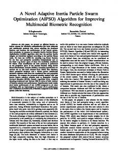
Fig. 1. Experimental setups of one-stage or two-stage adaptive PMD compensation for 40-Gb/s optical time-division-multiplexing transmission systems using the PSO algorithm.
Index Terms—Adaptive compensation, control algorithm, particle swarm optimization (PSO), polarization-mode dispersion (PMD).
II. ROLE OF CONTROL ALGORITHM IN ADAPTIVE PMD COMPENSATION
I. INTRODUCTION
A
DAPTIVE compensation for polarization-mode dispersion (PMD) may be one of the urgent tasks for next-generation high bit-rate optical fiber transmission systems. The control algorithm is critical in an adaptive PMD compensator. For adaptive PMD compensation using a feedback scheme, finding a practical feedback control algorithm with the desirable features is still a challenging task. In most of the related literature, the adopted control algorithms have not been explicitly characterized. In [1] and [2], the algorithm used as the control part of a PMD compensator employed gradient-based peak search methods. However, we found that as the numbers of control parameters increased, the gradient-based algorithm often became locked into local suboptima, rather than the global optimum. Besides, it would be less effective for a system with a relatively high noise level in the PMD monitor, because the gradient information between neighboring signals would be submerged in noise. We introduce particle swarm optimization (PSO) into adaptive PMD compensation as the control algorithm. This algorithm has the desirable features of rapid convergence to the global optimum without being trapped in local suboptima, and good robustness to noise.
Manuscript received April 9, 2004; revised August 19, 2004. This work was supported by the National “863” High Technology Projects under Grant 2001AA122041 and Grant 2003AA311070, and by the National Nature Science Foundation of China under Grant 60072042 and Grant 60377026. The authors are with the Department of Physics, School of Science, Beijing University of Posts and Telecommunications, Beijing 100876, China, and also with the Key Laboratory of Optical Communication and Lightwave Technologies, Ministry of Education, Beijing 100876, China (e-mail:
[email protected];
[email protected];
[email protected];
[email protected];
[email protected]). Digital Object Identifier 10.1109/LPT.2004.838150
For the schemes of optical postcompensation for PMD, it is widely believed that the one-stage compensators are able to compensate PMD to first order. They have three or four parameters [or degrees of freedom (DOF)] to be controlled depending on whether the differential group delay line is fixed or varied. The two-stage compensators can compensate the PMD up to the second order [3]. They have six or seven parameters (or DOF) to be controlled depending on whether the delay line is fixed or varied. (Here, the reason why we use three parameters instead of two to adjust polarization controllers (PCs) is that, from experiments, it is necessary to adjust at least three waveplates in order that a PC be able to transform a fixed input state of polarization to output states covering the entire Poincaré sphere.) The adaptive PMD compensation is a process for a control algorithm to find optimal combinations of control parameters, in order for the feedback signal to reach a global optimum, in an intelligent, fast, and reliable manner. In our experiment shown in Fig. 1, the degree of polarization (DOP), obtained by an in-line polarimeter, was used as feedback signal. The optical pulses at the receiving end have a DOP of one when there is no PMD in the fiber link, and the DOP value decreases as PMD increases [2]. The PC used in the compensation unit is the electrically controlled one which has four fiber-squeezer cells to be adjusted with voltage of 0–10 V, out of which three cells were used in the experiment. Thus, the problem of adaptive PMD compensation can be described mathematically as a problem of maximization of DOP (1) in brackets represents the DOP value in the where the experiment. The here are the voltages for controlling the PCs and the variable delay line. There is no simple method to predict in (1) in an adaptive PMD compensation system. A good searching algorithm is, therefore, required to solve problem (1), which is the problem of searching
1041-1135/$20.00 © 2005 IEEE
86
IEEE PHOTONICS TECHNOLOGY LETTERS, VOL. 17, NO. 1, JANUARY 2005
for a global maximum in a -dimensional hyperspace. The number is the number of DOF of the compensator. Generally, more DOF result in more submaxima existing, which increases the hard task of the searching algorithm. Therefore, it is more difficult for a searching algorithm to find the global optimum in second-order PMD compensation using the two-stage compensator than in first-order PMD compensation using the one-stage compensator. III. PSO OPTIMIZATION TECHNIQUE USED IN THE SEARCHING PROCESS OF THE CONTROL ALGORITHM
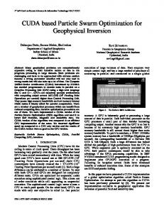
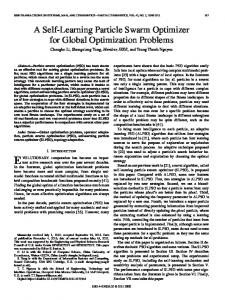
Fig. 2. Best DOP versus iteration recorded in 3-DOF first-order PMD compensation using (a) LPSO and (b) GPSO algorithm.
The PSO algorithm, proposed by Kennedy and Eberhart [4], has proved to be very effective in solving global optimization for multidimensional problems in static, noisy, and continuously changing environments [5]. We introduced for the first time the PSO technique into automatic PMD compensation for a 10-Gb/s system in our previous work [6], [7] and in the latest experiment described in Fig. 1 of this letter, where it has been shown to be effective. At the beginning, the PSO algorithm randomly initializes a population (called swarm) of individuals (called particles). Each particle represents a single intersection of multidimensional hyperspace. The position of the th particle is represented by the position vector . In the -dimensional-DOF PMD compensation scheme depicted in Fig. 1, the components of the th particle are represented by the combination of voltages . The particles evaluate their position relative to a goal at every iteration. In each iteration, every particle adjusts its trajectory (by its velocity ) toward its own previous best position, and toward the previous best position attained by any member of its topological neighborhood. If any particle’s position is close enough to the goal function, it is considered as having found the global optimum and the recurrence is ended. Generally, there are two kinds of topological neighborhood structures: global neighborhood structure, corresponding to the global version of PSO (GPSO), and local neighborhood structure, corresponding to the local version of PSO (LPSO). For the global neighborhood structure, the whole swarm is considered as the neighborhood, while for the local neighborhood structure, some smaller number of adjacent members in subswarm is taken as the neighborhood [8]. The detail of process for implementing the GPSO can be found in [8]. In the global neighborhood structure, each particle’s search is influenced by the best position found by any member of the entire population. In contrast, each particle in the local neighborhood structure is influenced only by parts of the adjacent members. Therefore, the LPSO has fewer opportunities to be trapped in suboptima than the GPSO. Generally, the larger the number of particles adopted in PSO, the fewer the opportunities to be trapped in suboptima, but the greater the time spent searching for the global optimum. In our experiment, 20 particles are used either in GPSO or LPSO, which is a balance between the accuracy required in searching for the global optimum and time consumed. It is found that having five neighbors for every particle gives the highest success rate in finding the global optimum [8]. In the adaptive PMD compensation experiment shown in Fig. 1, we made a comparison of effectiveness of both GPSO and LPSO, respectively, used in either 3-DOF one-stage or
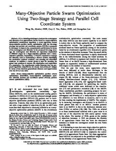
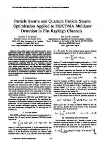
6-DOF two-stage PMD compensation. At first, we conducted the first-order PMD compensation experiments with one-stage compensator 18 times, by controlling the three voltages of the electrically controlled PC in the compensator through the GPSO and LPSO algorithms, respectively. We randomly selected the 18 different initial PMD states of the PMD emulator (corresponding to 18 different initial DOP values) for 18 different experiments. In every process of global DOP maximum searching, we recorded the variation of best DOP values in each iteration and, with the maximum iteration number set to 25, the results are shown in Fig. 2. It can be seen that all the final searched DOP values in any compensation process exceed 0.95 for both the GPSO or LPSO used as the control algorithm. Furthermore, all the DOP values reach 0.9 within about eight iterations for both GPSO and LPSO. The reasons why there is almost no difference between the cases using LPSO and GPSO are that fewer local suboptima existed and the low level of noise for the relatively simple configuration of the 3-DOF one-stage compensation system. Therefore, it is not so difficult for both GPSO and LPSO to perform successfully. Second, for comparison, we conducted 18 experiments of the second-order PMD compensation with the two-stage compensator by controlling six voltages of two PCs in the compensator, also through both the GPSO and LPSO algorithms. This time, the maximum iteration number for each searching process is set to 50, since we guess that it is a more difficult searching task because of the more complicated configuration or more DOFs, and a higher level of noise. The results are shown in Fig. 3(a) and (b). It is easy to draw the conclusion that, because there are more local submaxima and because there is a higher noise level in the 6-DOF system than in the 3-DOF system, for the GPSO case, there are some initial PMD states for which DOP only achieves the value of 0.7 [Fig. 3(b)], corresponding to being trapped in local suboptima. In contrast, for the LPSO case, all final searched DOP values exceed 0.9, no matter what the initial PMD state is. Furthermore, all the DOP values reach 0.9 within about 25 iterations. We can draw the conclusion that LPSO can better undertake the task of solving multidimensional problems, and that it is a better searching algorithm for adaptive PMD compensation up to high order. The response time of the compensator depends on the strategy of the chosen algorithms and the performance of the hardware including analog-to-digital (A/D), digital-to-analog (D/A), voltage-controlled PC, etc. We can define a time unit as the time used for one particle treatment in a PMD compensation loop. Many events happen in one time unit: 1) D/A converters writing multivoltages to the voltage-controlled PCs; 2) waiting
ZHANG et al.: PSO USED AS A CONTROL ALGORITHM FOR ADAPTIVE PMD COMPENSATION
Fig. 3. Best DOP versus iteration recorded in 6-DOF second-order PMD compensation using (a) LPSO and (b) GPSO algorithm.
for the PCs to reach their steady states; 3) multiple A/D conversions; 4) processing the data in the computer processor with the PSO algorithm. Then the next D/A conversion begins. In our experiment, one time unit was measured to be about 0.8 ms for the 3-DOF system and 1.1 ms for the 6-DOF system. One iteration (treating 20 particles) for searching is equivalent to 20 time units. If we set the DOP value to 0.9 as the criterion for which the goal of satisfactory compensation is considered to have been achieved, the compensation time used is (2) So for first-order compensation by the 3-DOF one-stage ms. For the compensator, this value is second-order compensation with the 6-DOF two-stage compenms. sator using the LPSO algorithm it is By analyzing the time used by every part of the hardware and the algorithm, we find that the PSO algorithm only occupies less than 16% of the whole time. Therefore, if we can afford high-speed hardware, a compensator having a faster speed with a real level of milliseconds can be achieved. IV. PSO TECHNIQUE USED IN THE TRACKING PROCESS OF THE CONTROL ALGORITHM The algorithm for real-time adaptive PMD compensation should include two stages. First, the searching algorithm finds the global optimum from any initial PMD condition. Then the tracking algorithm starts to track the changed optimum, because the PMD in the real fiber link always randomly changes, due to changes in the environment such as temperature fluctuations, etc. From our experiment, when the PMD in the fiber link changes, the global DOP maximum just drifts away from the previous location. In [7], we have introduced the dithering algorithm to track drifted DOP maximum in the tracking process of adaptive PMD compensation. In this letter, because of its good performance in the presence of noise and its multidimensional searching capability, we used the PSO searching technique in the smaller six-dimensional local space around the previous optimum location to achieve the goal of tracking changing optimum. After the global optimum search process is completed, the tracking algorithm starts to work according to the DOP values. When the DOP in the fiber link is higher than 98% of that obtained for the previous optimum, the algorithm does nothing. Otherwise, as long as the DOP is lower than this criterion, local space searching is initiated. The size of the local searching space is adjusted with time according to the deviation
87
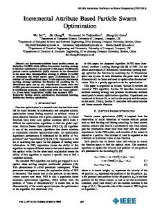
Fig. 4. Performance of the tracking algorithm for tracking the changed optimum DOP. (a) For a relatively long time frame, there are some sudden disturbances induced by sudden rotation of the PC of the emulator. (b) Details . of sudden disturbance
for from the criterion DOP, which is set to the experiment. For the tracking algorithm, five particles and GPSO were adopted because of the faster speed needed for tracking and the smaller space in which to search. In the experiment, the tracking algorithm worked well when slowly and smoothly rotating any one of the waveplates of the PC between pieces of the PMFs of the PMD emulator. The eye diagrams are nearly unchanged. Fig. 4 shows the tracking results with small vibration of DOP values around the criterion (0.88). But if we rotate the waveplate suddenly to make a sharp disturbance in the fiber link, the tracking algorithm will force the system rapidly to recover to the condition specified by the criterion. The recovery time is about ten time units [equivalent to 11 ms, Fig. 4(b)]. V. CONCLUSION For the first time, we have introduced the PSO algorithm into adaptive PMD compensation, which showed the desirable features of rapid convergence to the global optimum without being trapped in local suboptima and good robustness to noise. We also demonstrate that a time-varying PMD can be successfully tracked using the PSO technique. REFERENCES [1] R. Noé, D. Sandel, M. Yoshida-Dierolf, S. Hinz, V. Mirvoda, A. Schöpflin, C. Glingener, E. Gottwald, C. Scheerer, G. Fischer, T. Weyrauch, and W. Haase, “Polarization mode dispersion compensation at 10, 20, and 40 Gb/s with various optical equalizers,” J. Lightw. Technol., vol. 17, no. 9, pp. 1602–1616, Sep. 1999. [2] J. C. Rasmussen, “Automatic PMD and chromatic dispersion compensation in high capacity transmission,” in 2003 Dig. LEOS Summer Topical Meetings, 2003, pp. 47–48. [3] S. Kim, “Schemes for complete compensation for polarization mode dispersion up to second order,” Opt. Lett., vol. 27, no. 8, pp. 577–579, 2002. [4] J. Kennedy and R. C. Eberhart, “Paticle swarm optimization,” in Proc. IEEE Int. Conf. Neural Networks, Piscataway, NJ, 1995, pp. 1942–1948. [5] E. C. Laskari, K. E. Parsopoulos, and M. N. Vrahatis, “Particle swarm optimization for minimax problems,” in Proc. 2002 Congress Evolutionary Computation, vol. 2, 2002, pp. 1576–1581. [6] X. Zhang, L. Yu, Y. Zheng, Y. Shen, G. Zhou, and B. Yang, “Adaptive PMD compensation using PSO algorithm,” in OFC 2004, Los Angeles, CA, 2004, Paper ThF1. [7] Y. Zheng, X. Zhang, G. Zhou, Y. Shen, L. Chen, L. Yu, L. Xi, and B. Yang, “Automatic PMD compensation experiment with particle swarm optimization and adaptive dithering algorithms for 10-Gb/s NRZ and RZ formats,” IEEE J. Quantum Electron., vol. 40, no. 4, pp. 427–435, Apr. 2004. [8] J. Kennedy and R. Mendes, “Population structure and particle swarm performance,” in Proc. 2002 Congress Evolutionary Computation, vol. 2, 2002, pp. 1671–1676. [9] R. Eberhart and J. Kennedy, “A new optimizer using particle swarm theory,” in Proc. 6th Int. Symp. Micro Machine Human Sci., 1995, pp. 39–43.