Passive and Active Elements Using Fractional - IEEE Xplore
Recommend Documents
conditions under which L C impedance may act as a resistor, negative resistor, or a positive or negative pure imaginary inductor or capacitor, in accordance to ...
Accepted on 24th September 2015 doi: 10.1049/iet-com.2015.0216 www.ietdl.org. Azzam Al-nahari â. Department of Electrical Engineering, Ibb University, Ibb, ...
In this work, an integration of microwave data coming from different sensors (SMAP, Sentinel-1, AMSR2) has been attempted, in order to obtain an improved ...
Airbus A-320 it is expected that aircraft with such a control system may be equipped with a side stick controller for manual flight control. At the Faculty of.
Naval Physical and Oceanographic Laboratory, Kochi, India. Email: [email protected]. â . Rajagiri School of Engineering and Technology, Kochi, ...
AbstractâWaveguides and passive integrated optics elements constructed from thin metal films of finite width embedded in a homogeneous background ...
Interference Cancellation with Self-interference. Constraint for Cognitive OFDM System. Daiming Qu1, Zhiqiang Wang1, Tao Jiang1, Mahmoud Daneshmand2.
a first-order stationary process since its first-order increments. [fractional Gaussian noises (fGn)] are stationary. The interest of. fBm is that it simply represents, ...
Abstractâ A study is conducted on time series data analysis relating the concept of the ... the fractal dimension. A new definition of the fractal dimension is.
AbstractâThe self similar branching arrangement of the air- ways makes the respiratory system an ideal candidate for the application of fractional calculus ...
Therefore mitigations of harmonics have been considered as important research issues in power system. A growing number of different harmonic mitigation ...
Target Detection in High Clutter using Passive Bistatic WiFi Radar. Kevin Chetty, Graeme Smith, Hui Guo and Karl Woodbridge. Department of Electronic ...
polarization diverse nature of the vector sensor is developed. It is also shown that the direction finding performance provided by a conventional array calibration ...
Kun-You Lin, Member, IEEE, Wen-Hua Tu, Ping-Yu Chen, Hong-Yeh Chang, Student Member, ... utilizing a p-i-n diode have demonstrated good performance.
The basic configuration is a microchannel with two inlets, three outlets, and obstacles that increase the ..... J.M. Park, K.D. Seo and T.H. Kwon, âA chaotic.
Chen Li, Qiulin Tan, Wendong Zhang, Senior Member, IEEE, Chenyang Xue, and Jijun Xiong. AbstractâThis paper presents an embedded wireless passive.
Passive and Active Transport. 1. Thermodynamics of transport. 2. Passive-
mediated transport. 3. Active transport neuron, membrane potential, ion transport
...
tude-modulated signal corrupted with high-frequency chirp noise. Index TermsâCaputo fractional derivative, fractional Fourier transform (FrFT), fractional order ...
PASSIVE AND ACTIVE VOICE. A. Put the verbs into the correct passive tense:
Simple Present. 1. English (teach) in this school. 2. The room (clean) every day. 3
.
Active and passive sentences usually have the same meaning but the focus is ...
Passive present simple. She does the homework. am/are/is + past participle.
AbstractâAn integral method for computation of static mag- netic fields exploits Whitney facet elements for approximation of magnetization of arbitrary solids or ...
Machine With Consequent Pole Rotor for Low Speed Direct Drive ... Electric Motor Research Center, Korea Electrotechnology Research Institute, Changwon ...
The commonly used fractional calculus definitions in the domain of ... The Riemann-Liouville definition of the v-order integral, ...... the inverse Fourier transforms of ( )v ...... [21] B. Song, âTopics in Variational PDE Image Segmentation, Inpai
On Universality in Fractional Dynamics. Mark Edelman. Department of Physics. Stern College at Yeshiva University. 245 Lexington Avenue, New York, NY ...
Passive and Active Elements Using Fractional - IEEE Xplore
2388. IEEE TRANSACTIONS ON CIRCUITS AND SYSTEMSâI: REGULAR PAPERS, VOL. 58, NO. 10, OCTOBER 2011. Passive and Active Elements Using.
2388
IEEE TRANSACTIONS ON CIRCUITS AND SYSTEMS—I: REGULAR PAPERS, VOL. 58, NO. 10, OCTOBER 2011
Passive and Active Elements Using Fractional L C Circuit A. G. Radwan, Member, IEEE, and K. N. Salama, Senior Member, IEEE
Abstract—This paper introduces a qualitative revision of the traditional LC tank circuit in the fractional domain. The paper can be divided into six major parts, aiming in turn to establish the various conditions under which L C impedance may act as a resistor, negative resistor, or a positive or negative pure imaginary inductor or capacitor, in accordance to new frequency definitions; illustrate the process by which the phase response chooses the shortest path from initial to final phase, and use this illustration to verify the cases discussed in part one; develop the generalized parameters for the bandpass filter response of the L C circuit, such as the resonance frequency and quality factor versus plane; discuss sensitivity analyses with respect to the fractional orders, as well as the time domain analyses for the impulse and step responses with their analytical formulas; and lastly, to propose some possible applications for this generalized circuit. Mathematical and PSpice simulation results are included to validate the discussion. Index Terms—Negative resistor, resonance, quality factor, sensitivity analysis, fractional oscillation.
I. INTRODUCTION ALCULUS of integer orders was once the basic essential mathematical tool for analysis, synthesis, response behavior, theorems, and many novel applications for any dynamical system from 1695 until 1960. However, these integer values are a very narrow subset of the real orders, and so during the last five decades, a dramatic shift has taken place and many scientific researchers have been concerned instead with fractional calculus [1], [2]. In particular, these scientists have attempted to broaden the scope of fundamentals and theorems from integer order systems into fractional ones, since many achievements are obtained as a result of employing the extra fractional-order variables, allowing for more flexibility, freedom, best fit, and optimization techniques. Furthermore, many new fundamentals have been investigated only in the fractional-order sense. Several physical phenomena have been restudied using the tools of fractional calculus, with a great improvement over the traditional analysis as well as better accuracy when comparing
C
Manuscript received September 27, 2010; revised January 29, 2011; accepted March 28, 2011.Date of publication May 19, 2011; date of current version September 28, 2011. This paper was recommended by Associate Editor I. M. Filanovsky. A. G. Radwan is with the Electrical Engineering Program at King Abdullah University of Science and Technology (KAUST), Thuwal 23955-6900, Saudi Arabia and also with the Faculty of Engineering, Cairo University, Cairo 12613, Egypt (e-mail: [email protected]; [email protected]). K. N. Salama is with the Electrical Engineering Program, King Abdullah University of Science and Technology (KAUST), Thuwal 23955-6900, Saudi Arabia. (e-mail: [email protected]). Color versions of one or more of the figures in this paper are available online at http://ieeexplore.ieee.org. Digital Object Identifier 10.1109/TCSI.2011.2142690
the experimental data, for instance in biomedical, chemical, and agricultural [3]–[6] applications. The relations between current and voltage in the traditional circuit theory are based on three elements: the resistor (R), the inductor (L), and the capacitor (C). As is known, the phase difference between current and voltage for any fractional element is linearly dependent on the fractional-order and could be varied over the full 2 phase. Many practical realizations and patents of the fractional element have been proposed during the last 20 years [7]–[14], in particular the half-order capacitor, which has been realized through different techniques including the frequency-dependent of the dielectric properties of some materials; for example, LiN H SO “Fractor” [8], equivalent RC tree circuit [12], chemical reaction probe [13], and fractal structures [14]. Recently, many theorems and procedures which are generalized with experimental results based on the realization of fractional-order circuits [7], [8], [12] have been introduced in different fields. These theorems and procedures include control theorems [15]–[19], circuit theorems [20]–[22], memristor-based systems [23], [24], digital designs [25], [26], novel fractional-order Smith charts [27], [28], and stability analysis [29], [30], which is essential for the existence of fractional-order circuits. Practically, by studying the behavior of Coilcraft RF inductors [31] from 1 MHz to 1.8 GHz, the skin effect losses were , similar to the half-order inductor. modeled as Also, the characteristic impedance Z of a lossy transmission line was modeled as a half order element [32]. Although, the conventional LC circuit was discussed previously, novel theorems and analyses are still being researched [33], [34]. The fraccircuit has an advantage over any traditional L C tional because it is a function of the circuit parameters (C, L) in addi. tion to two extra fractional-orders In this paper, a generalization of the fundamentals of the circuit is introduced, taking into consideration all possible cases that can be modeled using this circuit. In Section impedance is II, a generalization for the fractional-order discussed, where a positive resistor, negative resistor, inductor, capacitor, and short circuit were obtained. Frequency definitions , pure imaginary such as the pure real angular frequency and short circuit angular frequency angular frequency are proposed for the first time. The phase response verifications for the existence of these previous cases are graphically introduced in Section III. The generalized formulas of the resonance and quality factor Q of the bandpass filter frequency as functions of the fractional-orders are discussed in Section being easily controlled for IV; the resonance frequency
RADWAN AND SALAMA: PASSIVE AND ACTIVE ELEMENTS USING FRACTIONAL
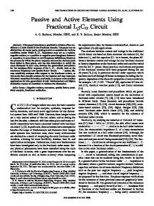
Fig. 1. (a) Series connection of L
C
CIRCUIT
2389
circuit and (b) its phasor diagram.
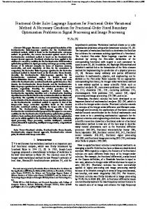
Fig. 2. (a) The existence region of the pure real angular frequency ! the sign of the pure real (+R; R) impedance as function of .
0
and (b)
wider ranges of the quality factor. Section V discusses the sensitivities of the amplitude response with respect to both of the fractional-orders. The time-domain closed form for impulse and step responses as a function of the known Mittag-Leffler function [2], [35]–[38], and the R function [34], supported with some numerical simulations, are demonstrated in Section VI. The last section proposes some applications such as the realization of high narrowband inductor or a capacitor based on very small fractional-order element values. Also, a simple can act as a circuit to prove that the fractional-order negative resistor is introduced, as well as another example with free oscillation. Finally, a comparison table that summarizes the differences between the traditional and the fractional version of the LC tank is introduced. II. FRACTIONAL-ORDER LC TANK circuit can oscillate freely at a The conventional frequency . The impedance of this circuit is always pure inductive or capacitive according to whether or respectively. The series connection of and its phasor diagram are shown the fractional-orders in Fig. 1. Each fractional-order phasor has real and imaginary components. At specific relationships between the parameters , the resultant vector can be pure real, pure imaginary, and zero vectors. The Laplace form of the fractional impedance of Fig. 1(a) is . By substituting in given by Z(s), the frequency-dependent impedance is given by
(1) A. Case of Pure Real Impedance The fractional impedance could be pure real at a specific frequency, which we define as a pure real an-
Fig. 3. The pure real angular frequency ! L = 0:001, and C = 0:00001.
as function of (a) and (b) when
gular frequency . At this frequency, the fractional impedance is given by (2a), where is given by (2b). Conventionally, , and . these formulas will be reduced to Generally, (2a), (2b) could be controlled by the fractional-or, which are used to extend their range from very low ders to extremely high values. Since in (2b) depends only on function, the pure real angular frequency exists the as shown in for the completely accepted range Fig. 2(a). According to (2a), the pure real impedance may be ) or negative (act as ) when positive (act as or respectively as shown in Fig. 2(b). (2a) (2b) Fig. 3(a) shows the values of at four different values of , and 1.5 versus . The range of is affected more greatly by the value of as shown in Fig. 3(b). becomes very As grows smaller and closer to zero, high. Also, as increases, the value of decreases to a specific minimum value as shown in Fig. 3(b), then goes to infinity . The absolute value of the fractional impedance at as is shown in Fig. 4, where the minimum peaks take place at free oscillation cases. Before and after these peaks, the circuit acts as a positive/negative resistor. These two cases cannot exist in the
2390
IEEE TRANSACTIONS ON CIRCUITS AND SYSTEMS—I: REGULAR PAPERS, VOL. 58, NO. 10, OCTOBER 2011
Fig. 4. The absolute value of the impedance as a function of values of when L : , and C : .
= 0 001
= 0 00001
at different
Fig. 5. (a) Possible regions of the pure imaginary angular frequency (b) the sign of its pure imaginary impedance as function of .
Fig. 7. The absolute value of the impedance at ! : , and C : of when L .
= 0 001
!
= 0 00001
versus at different values
and
Fig. 8. All six possible special cases of the total impedance for the whole range of and .
Fig. 6. The pure imaginary angular frequency ! : , and C : values of when L
= 0 001
as function of at different
= 0 00001.
traditional . Also, the range of this pure impedance varies from extremely low to hundreds of K . B. Case of Pure Imaginary Impedance The fractional impedance could be pure imaginary at a certain where its value as well as pure imaginary angular frequency the pure imaginary impedance are as given in (3a), (3b). This or pure imaginary angular frequency exists only if as shown in Fig. 5(a). This means that, for any value as of , only half of the range of is acceptable to obtain , and . in Fig. 6 when (3a) (3b)
For each the values of have a maximum peak at , where the range of this critical parameter is limited to . The values of have different characteristics with different values. The only point at which the impedance will always be imagdomain is the integer case inary independent of on the . The absolute value of the pure imaginary is given in Fig. 7, where the sign of this imaginary quantity is obtained according to the relationship between the fractional-orders. The impedance is pure positive imaginary (acting as an inand pure negative imaginary ductor) if as shown in (acting as a capacitor) if Fig. 5(b). Equation (3) shows the pure imaginary impedance at spanning wide ranges (see Fig. 7). C. Case of Short-Circuit Impedance can oscillate, under short circuit The fractional circuit as in [20], which is satisfied connection only if under the traditional case of integer orders. The frequency of which oscillation is still is the same as in integer case. By this approach we can get the same frequency of oscillation for infinite pairs of fractional-or. ders
RADWAN AND SALAMA: PASSIVE AND ACTIVE ELEMENTS USING FRACTIONAL
CIRCUIT
Fig. 9. The locus of the initial point, final point, and the four special cases on the circular phase map of the total impedance (a) in case of response rotates in counterclockwise direction and (b) in case of > , where the response rotates in clockwise direction.
+
2
III. PHASE RESPONSE , the total impedance is dominated by the fractionalAs order capacitor. In this case the initial phase will be . , However, at very high frequencies such as when the fractional-order inductor will dominate the circuit and the . The phase response always chooses final phase will be the shortest path while moving from the domination of fractional-order capacitor to the fractional-order inductor as frequency increases. As demonstrated, the total impedance of the circuit can act as a positive resistor, negfractional-order ative resistor, inductor, capacitor and short circuit. Therefore, plane is divided unequally into six regions, which the represent six different possibilities (Fig. 8). In two quarters of this plane, the total impedance will pass by only one point: either zero-phase (positive resistor) or -phase (negative resistor). However, double alternatives (four cases) could exist in the other half plane. If a frequency-scan has been applied to this circuit at a certain for the whole range of frequencies from , value of one of the six possible cases will take place. Significant questions remain unanswered, such as why the circuit changes its to as and change, and which is performance from greater, or in the case of two possibilities for different . pairs To answer these questions, the generalized phase response of the total impedance for this circuit is studied for its direct relationship with the existence of these elements as zero phase (as inductor) and (as capacitor). The
2391
+ < 2, where the
of any complex number angle or argument is given by (4), at the bottom of the page. A. Region I: There are three different regions under this constraint, as shown in Fig. 8. The common issue in this region is that when the total impedance becomes real, the phase must be zero (the total impedance acts as a positive resistor). However, both or may occur separately, one at a imaginary cases time. In this region the phase response is continuous and will go counterclockwise as the frequency increases. If and then the response will pass only through the positive resistive , the initial phase case (zero-phase). However, when response is less than and hence, the phase must pass then by the resistive case at first by the inductive case at . Therefore, in this case , and vice versa in the as shown in Fig. 9(a). Consequently the phase case of response chooses the shortest path and goes forward to zero phase. In addition, it is impossible for the total impedance of the series connection of two fractional-order capacitors or inductors (of the same type) to show pure real case, as they will or . not pass by any of the two extreme points Fig. 10 shows the phase response for three different cases in only, the other passing this region; one passing through and the last passing by . The phase through response in this region always increases as the frequency increases.
(4)
2392
IEEE TRANSACTIONS ON CIRCUITS AND SYSTEMS—I: REGULAR PAPERS, VOL. 58, NO. 10, OCTOBER 2011
TABLE I THE RESONANCE FREQUENCY (RAD/S) FOR DIFFERENT VALUES OF AND WHEN LC = 10 WHERE T = 10 ; G = 10 ; M = 10 , AND K = 10
Fig. 10. The phase response of the total impedance Z(j!) for region I, when ( + ) < 2 with three different cases which covered all three possible cases.
the initial to the final phase at the frequency of oscillation at which point the system will oscillate freely [20]. The total impedance will be zero and the phase in this case will be undefined as shown in (4) since both real and imaginary components are zeros. IV. RESONANCE PARAMETERS
Fig. 11. The phase response of the total impedance Z(j! ) for region II, when ( + ) > 2 with three different cases which covered all three possible cases.
B. Region II: In this region, the clockwise direction (which passes through ) is shorter than the counterclockwise direction (which ), and the phase response will follow the passes through shortest path as shown in Fig. 9(b). In all cases included in this region, the total impedance can act as a negative resistor when . Thus, the phase will begin at and go backward , then from down to . The phase is discontinto . Fig. 11 illustrates three different cases, when uous at , then as shown in the second graph, and simiin case when . Here the relationship belarly, tween pure real and imaginary angular frequencies depends on the fractional-orders. The phase response in this case decreases as the frequency increases. C. Region III: In this case, both clockwise and counterclockwise paths are equal since the difference between the initial and final phases is . This means that the phase response will jump suddenly from
Because the magnitude response is very high in both extreme cases; for very low frequencies (dominant is fractional capacitor) and very high frequencies (dominant is fractional-order inductor), the magnitude response of the total impedance/adcircuit will become a mittance of the fractional-order notch/bandpass filter. The resonance frequency of such response is easily obtained by (5), at the bottom of the next page. There exist many asymptotic curves of the resonance frequency according to the relationship between and as follows: • • • Table I shows the wide range of the resonance frequency down to a few hundred rad/s when . from of the generalTherefore, the additional free parameters ized circuit could control the location of the center (resonance) frequency. The 3-D-surface plot for this minimum magnitude response at the resonance frequency when and is illustrated in Fig. 12; where the main diagonal has a zero impedance due to the free-oscillation condition. The minimum magnitude response of the generalized fraccircuit is nonsymmetrical with respect to tional-order and since it depends on the element values of and in addition to the center frequency. Fig. 13 illustrates the magnitude response of the admittance versus angular frequency for the four different cases of fractional-orders. The amplitude response is not the same if and are interchanged together as shown in Fig. 12, although they almost have the same resonance frequency as shown in Table I. This is due to the dependence of
(5)
RADWAN AND SALAMA: PASSIVE AND ACTIVE ELEMENTS USING FRACTIONAL
Fig. 12. The magnitude response for the total impedance at the resonance frequency ! versus plane when L : , and C : .
0
= 0 001
= 0 00001
CIRCUIT
2393
LC
Fig. 15. The relation between which produce critical value of the magnitude response with respect to both , and .
was discussed through the resonance analysis. The magnitude response with respect to or will have a peak if there exist or to satisfy the following equations respectively: either
(6a)
(6b)
Fig. 13. The magnitude response for the total admittance versus frequency for : , and C : . different values of and when L
= 0 001
= 0 00001
Fig. 15 shows the relation between the product value with the critical values of fractional-orders when rad/s and for different values of the other fractional-order. Solid at given values of and others for curves are related to . As shown in Fig. 15, it is not necessary for the response to . However, the have a critical value such as default cases do have a critical value, for example, at half-order and rad/s. Let us assume that the inductor , is therefore the best value of critical fractional-order and when , then (LC) . The magnitude responses as a function of for these two cases are shown in Fig. 16. Fig. 14. The quality factor versus : . : , and C
0 001
= 0 00001
for different values of
when L
=
on and which is a considerably effective value, especially for high frequencies. As is known, this circuit oscillates when the sum of its fractional-orders is two. So, the expected quality factor of the total impedance curve will reach its maximum at this condition, but far from this point the quality factor will decrease as illustrated in Fig. 14. V. SENSITIVITY ANALYSIS Sensitivity analysis plays a crucial role in optimizing the target response by the best values of parameters in inverse problems [6]. In the previous section, the sensitivity of the magnitude response, with respect to the angular frequency,
VI. TIME DOMAIN ANALYSIS This section demonstrates the time domain response of the circuit. Theoretically, the impulse and step generalized responses of the conventional integer-order circuit are and functions respectively. These sustained oscillations always happen due to the absence of lossy elements as resistors. At any time, the total input energy will be stored between the inductor L and capacitor C. However, the existence of pure inductor and capacitor is impossible, and the skin effects must be taken into consideration, as shown in [31], [32]; in such cases, energy will decay with time. Many generalized functions for the direct solution and principles for the linear fractional-order differential equations (LFDEs) were proposed in [2], [35]–[38]. The most important function was proposed in 1903 and is called Mittag-Leffler (t). This was later generalized by Agarwal in 1953, function
2394
IEEE TRANSACTIONS ON CIRCUITS AND SYSTEMS—I: REGULAR PAPERS, VOL. 58, NO. 10, OCTOBER 2011
Fig. 16. The magnitude response versus showing the critical values and their locations when the angular frequency was 10 rad/s at = 0:5.
and by Erdely in 1954. Many closed form solutions of LFDEs can be obtained using these functions. Recently, novel functions such as F and R functions have been introduced for the solution of more LFDEs [35]. Generally, the Laplace transform of the current passing in the circuit is given by (7) The impulse response of this circuit, when for simplicity, can be obtained by the Agarwal’s generalized MittagLeffler and the R functions. The definitions of these functions and their Laplace transform [35]–[38] are given as follows:
Fig. 17. The impulse and step responses of the L C circuit when L = C = 1 (a) and (b) for different and fixed = 1, and (c) and (d) for different and fixed = 1.
in the , equal to order fractional-order .
, versus the time and the
VII. APPLICATIONS (8a) (8b) (8c) (8d)
A. Narrowband High Inductor Realization Many applications operate on a single frequency or a very narrow frequency range. Hence, this circuit could be used to realize a high-value inductor at a specific frequency. From (3b), will be positive at a certain range of and as shown in Fig. 5(b). Then this impedance can act as an integer inductor in . The ratio of the equivalent integer-order the narrowband of inductor to the actual fractional-order is given by
Therefore, the closed form of time-domain impulse response is (10)
(9) For a special case of half order capacitor and inductor, the impulse and step closed form responses can be written as a function of the known hypergeometric and error functions respectively. Fig. 17 shows the decaying behavior of the impulse and step responses for seven different cases when is equal , to , and . However, Fig. 18 illustrates the smoothing step response of the 3-D surface of current flowing
Fig. 19 shows the ratio between the equivalent inductor and the rad s versus actual inductor in the circuit at . If the required ratio is , then . In order to acquire the actual value of the circuit capacitor, the other curve in Fig. 19 describes the reciprocal of the product of the actual circuit in, then , ductor and capacitor. If or an equivwhich produces an impedance mH. Thus, we can model and alent integer inductor realize any high value integer-order inductor at high frequencies by using very small values of fractional-order. Moreover, if this ratio can realize a very small integer-order inductor at high frequency. The same discussion could be
RADWAN AND SALAMA: PASSIVE AND ACTIVE ELEMENTS USING FRACTIONAL
Fig. 18. The step response of the L and the fractional-order .
C
circuit (
= ) as function of time
Fig. 19. The ratio between the equivalent to the circuit inductor and the reciprocal of the product of both circuit inductor and capacitor as function of when ! = 100 M rad=s, and = 0:2.
applied in the case of high-value integer-order capacitor through making use of small-value fractional-order elements. B. Narrowband Realization of Negative Resistor The importance of designing the negative resistor has been increased during the previous few decades due to its significant role in many nonlinear applications. To check that a negative retank, sistance could be obtained from the fractional-order a series positive resistance is added with same value. , Therefore, the total impedance will vanish circuit to oscillate freely. For exwhich enhances the ample when , the impedance when , when . as shown in Fig. 4, such as will oscillate if This means that the series circuit using the previously mentioned values. Fig. 20 shows the PSpice simulation result for this circuit at mH, (integer inductor), and . This result confirms the previous mathematical study and could also be obtained by studying the stability of this circuit [20]. Then, , the poles will be located in the unstable region. if However, the added positive resistance returns them back to the j axis (critically stable).
CIRCUIT
2395
Fig. 20. PSpice transient simulation result for series
0:001; C = 0:00001; and R = 1:34 .
L C R when L =
Fig. 21. PSpice transient simulation result for series L
C
.
C. Free Oscillation of According to the previous discussions concerning the free os, the PSpice circuit simulation cillation condition and . The result is shown in Fig. 21, where, oscillation is very smooth, resembling the oscillation of the integer order. The frequency of oscillation is independent of the fractional-orders used in this circuit controlled by the value of , and . with . VIII. CONCLUSION This paper attempts to generalize the impedance of fractionalcircuit to realize , and the short cirorder cuit case. New frequency definitions were proposed for the first time to achieve these cases which were then verified using phase bandresponse analysis. Generalized parameters of the pass filter response were introduced. Also, several sensitivity analyses were discussed, with respect to the fractional-orders. Time domain impulse and step responses were discussed analytically as a function of the Mittag-Leffler function. In Table II and its the basic differences between the fractional-order integer one were summarized, showing that the integer case is just one point inside this entire domain. All these features were
2396
IEEE TRANSACTIONS ON CIRCUITS AND SYSTEMS—I: REGULAR PAPERS, VOL. 58, NO. 10, OCTOBER 2011
TABLE II MAIN DIFFERENCES BETWEEN FRACTIONAL-ORDER L
supported with closed form formulas, numerical analysis and PSpice circuit simulations to verify these concepts. Due to the skin effect of practical RF inductors and capacitors which are modeled as half order elements, there could be a large number of applications for these fundamentals, instead of the traditional integer model for achieving more flexibility, controllability and aid in curve fitting or optimization.
REFERENCES [1] S. G. Samko, A. A. Kilbas, and O. I. Marichev, Fractional Integrals and Derivatives: Theory and Application. Philadelphia, PA: Gordon & Breach, 1987. [2] J. Sabatier, O. P. Agrawal, and J. A. T. Machado, Advances in Fractional Calculus; Theoretical Developments and Applications in Physics and Engineering. New York: Springer, 2007. [3] R. L. Magin, Fractional Calculus in Bioengineering. Redding, CT: Begell House, 2006. [4] C. M. Ionescu and R. De Keyser, “Relations between fractional-order model parameters and lung pathology in chronic obstructive pulmonary disease,” IEEE Trans. Biomed. Eng., vol. 56, no. 4, pp. 978–987, 2009. [5] R. Martin, J. J. Quintara, A. Ramos, and L. De La Nuez, “Modeling electrochemical double layer capacitor, from classical to fractional impedance,” in Proc. IEEE Conf. Electrotech., 2008, pp. 61–66. [6] I. S. Jesus, T. J. A. Machado, and B. J. Cunha, “Fractional electrical impedances in botanical elements,” J. Vibration Control, vol. 14, no. 9–10, pp. 1389–1402, Sep. 2008. [7] G. W. Bohannan, S. K. Hurst, and L. Springler, “Electrical Component with Fractional-Order Impedance,” US20060267595, 11 30, 2006, Utility Patent Application. [8] G. W. Bohannan, “Analog realization of a fractional control elementrevisited,” in Proc. 41st IEEE Int. Conf. Decision Control, Tutorial Workshop 2: Fractional Calculus Applications in Automatic Control and Robotics, 2002, pp. 203–208. [9] G. Carlson and C. Halijak, “Approximation of fractional capacitors (1/s) by a regular Newton process,” IEEE Trans. Circuits Syst, vol. CAS-11, pp. 210–213, 1964. [10] A. Abbisso, R. Caponetto, L. Fortuna, and D. Porto, “Non-integerorder integration by using neural networks,” in Proc. Int. Symp. Circuits Syst., 2001, vol. 38, pp. 688–691. [11] K. Saito and M. Sugi, “Simulation of power-law relaxations by analog circuits: Fractal distribution of relaxation times and non-integer exponents,” IEICE Trans. Fundam. Electron. Commun. Comput. Sci., vol. E76, no. 2, pp. 205–209, 1993.
C
AND INTEGER
LC
CIRCUITS
[12] M. Nakagawa and K. Sorimachi, “Basic characteristics of a fractance device,” IEICE Trans. Fundam. Electron. Commun. Comput. Sci., vol. E75, no. 12, pp. 1814–1819, 1992. [13] K. Biswas, S. Sen, and P. Dutta, “Realization of a constant phase element and its performance study in a differentiator circuits,” IEEE Trans. Circuits Syst. II, Exp. Briefs, vol. 53, pp. 802–806, 2006. [14] T. C. Haba, G. L. Loum, and G. Ablart, “An analytical expression for the input impedance of a fractal tree obtained by a microelectronical process and experimental measurements of its non-integral dimension,” Chaos, Solitons, Fractals, vol. 33, pp. 364–373, 2007. [15] P. Melchior, B. Orsoni, O. Lavialle, and A. Oustaloup, “The CRONE toolbox for Matlab: Fractional path planning design in robotics,” Int. J. Circ. Theor. Appl., vol. 36, pp. 473–492, 2008. [16] H. Li, Y. Luo, and Y. Q. Chen, “A fractional-order proportional and derivative (FOPD) motion controller: Tuning rule and experiments,” IEEE Trans. Control Syst. Tech., vol. 18, no. 2, pp. 516–520, 2010. [17] C. C. Tseng and S. L. Lee, “Design of fractional-order digital differentiator using radial basis function,” IEEE Trans. Circuits Syst. I, Reg. Papers, vol. 57, no. 7, pp. 391–404, 2010. [18] S. Mukhopadhyay, C. Coopmans, and Y. Q. Chen, “Purely analog fractional-order PI control using discrete fractional capacitors (Fractals): Synthesis and experiments,” presented at the Int. Design Eng. Tech. Conf. Comput. Inf. Eng. Conf. (IDETC/CIE), San Diego, CA, 2009. [19] H. Sheng, H. Sun, C. Coopmans, Y. Q. Chen, and G. W. Bohannan, “Physical experimental study of variable-order fractional integrator and differentiator,” in Proc. 4th IFAC Workshop Fractional Differentiation Its Appl., 2010, pp. 18–20. [20] A. G. Radwan, A. S. Elwakil, and A. M. Soliman, “Fractional-order sinusoidal oscillators: Design procedure and practical examples,” IEEE Trans. Circuits Syst. I, Reg. Papers, vol. 55, pp. 2051–2063, Aug. 2008. [21] A. G. Radwan, A. S. Elwakil, and A. M. Soliman, “On the generalization of second-order filters to fractional-order domain,” J. Circuits Syst. Comput., vol. 18, no. 2, pp. 361–386, 2009. [22] B. Maundy, A. S. Elwakil, and S. Gift, “On a multivibrator that employs a fractional capacitor,” J. Analog Integr. Circuits Signal Process., vol. 62, pp. 99–103, 2010. [23] C. Coopmans, I. Petras, and Y. Q. Chen, “Analogue fractional-order generalized memristive devices,” in ASME 2009 Int. Design Eng. Tech. Conf. Comput. Inf. Eng. Conf. (IDETC/CIE), San Diego, CA. [24] A. G. Radwan, K. Moaddy, and S. Momani, “Stability and nonstandard finite difference method of the generalized Chua’s circuit,” Int. J. Comput. Math. Appl., to be published. [25] H. K. Kwan and A. Jiang, “FIR, allpass, and IIR variable fractional delay digital filter design,” IEEE Trans. Circuits Syst. I, Reg. Papers, vol. 56, no. 9, pp. 2064–2074, 2009. [26] Y. Q. Chen and K. L. Moore, “Discretization schemes for fractional-order differentiators and integrators,” IEEE Trans. Circuits Syst. I, Fundam. Theory Appl., vol. 49, no. 3, pp. 363–267, 2002.
RADWAN AND SALAMA: PASSIVE AND ACTIVE ELEMENTS USING FRACTIONAL
[27] A. Shamim, A. G. Radwan, and K. N. Salama, “Fractional Smith chart theory and application,” IEEE Microw. Wireless Compon. Lett., vol. 21, no. 3, pp. 117–119, 2011. [28] A. G. Radwan, A. Shamim, and K. N. Salama, “Theory of fractionalorder elements based impedance matching networks,” IEEE Microw. Wireless Compon. Lett., vol. 21, no. 3, pp. 120–122, 2011. [29] Y. Q. Chen, A. Hyo-Sung, and I. Podlubny, “Robust stability check of fractional-order linear time invariant systems with interval uncertainties,” Signal Process., vol. 86, no. 10, pp. 2611–2618, 2006. [30] A. G. Radwan, A. M. Soliman, A. S. Elwakil, and A. Sedeek, “On the stability of linear systems with fractional-order elements,” Chaos, Solitons, Fractals, vol. 40, no. 5, pp. 2317–2328, Jun. 2009. [31] Modeling Coilcraft RF Inductors. Coilcraft Document 158 May 1999 [Online]. Available: http://www.coilcraft.com [32] C. S. Yen, Z. Fazarinc, and R. L. Wheeler, “Time-domain skin-effect model for transient analysis of lossy transmission lines,” Proc. IEEE, vol. 70, pp. 750–757, Jul. 1982. [33] A. Buonomo and A. Lo Schiavo, “On the theory of quadrature oscillations obtained through parallel LC VCOs,” IEEE Trans. Circuits Syst. I, Reg. Papers, vol. 57, no. 9, pp. 2509–2519, 2010. [34] D. Murphy, J. J. Rael, and A. A. Abidi, “Phase noise in LC oscillators: A phasor-based analysis of a general result and of loaded Q,” IEEE Trans. Circuits Syst. I, Reg. Papers, vol. 57, no. 6, pp. 1187–1203, 2010. [35] H. J. Seybold and R. Hilfer, “Numerical results for the generalized Mittag-Leffler function,” Int. J. Theory Appl., Fractional Calculus Appl. Anal., vol. 8, no. 2, pp. 127–139, 2005. [36] C. F. Lorenzo and T. T. Hartley, “R-function relationships for application in the fractional calculus,” National Aeronautics and Space Administration (NASA/TM-2000-210361), Glenn Research Center, Aug. 2000. [37] C. F. Lorenzo and T. T. Hartley, “Generalized functions for the fractional calculus,” National Aeronautics and Space Administration (NASA/TP—1999-209424/REV1), Glenn Research Center, Oct. 1999. [38] I. Podlubny, Fractional Differential Equations. San Diego, CA: Academic, 1999.
CIRCUIT
2397
Ahmed G. Radwan (M’97) received the B.S. degree (with honors) in electrical and electronic engineering and the Condensed Diploma, Master’s, and Doctoral degrees in applied engineering mathematics from Cairo University, Cairo, Egypt, in 1997, 1999, 2002, and 2006 respectively. He joined the Department of Applied Engineering Mathematics at Cairo University since 1997, where he became Assistant Professor in 2006. Currently, he is with King Abdullah University of Science and Technology, Saudi Arabia as a temporary visiting scholar. He was invited as a visiting professor in the computational electromagnetic lab in the electrical engineering department, McMaster University, Hamilton, ON, Canada, from 2008 to 2009. He introduced many generalized theorems in the fractional order circuit, and the coinventor of the fractional Smith-Chart. He is the first author of more than 30 international journal papers in different scientific journals, and two provisional patents, and one book chapter. His main research interests are in the fields of nonlinear circuit analysis, chaotic and fractional order differential equations and circuits, stability analysis, memristor-based circuit design and modeling, and electromagnetic computational techniques. Dr. Radwan’s papers are cited in many recent international journals and books. He is permanent reviewer of many different scientific journals. He received the Best Thesis Award from Cairo University for his M.Sc. thesis.
Khaled N. Salama (M’96–SM’10) received the B.S. degree (with honors) from Cairo University, Giza, Egypt, in 1997 and the M.S. and Ph.D. degrees from Stanford University, Stanford, CA, in 2000 and 2005, respectively. Between 2005 and 2009, he was an Assistant Professor with the Department of Electrical, Computers and Systems Engineering, Rensselaer Polytechnic Institute, Troy, NY. He cofounded Ultrawave Labs, a medical imaging startup, in 2007, and serves as its Vice President of Research and Development. Since Fall 2009, he has been an Assistant Professor of Electrical Engineering and its founding acting program chair with the King Abdullah University of Science and Technology, Thuwal, Saudi Arabia. He has coauthored 70 papers and four patents in the areas of biosensors, low power mixed-signal circuits for intelligent sensors, and medical instrumentation. Dr. Salama was elected to the IEEE Sensory Systems and the IEEE Bio-Circuits Technical Committees in 2006 and to the IEEE VLSI Systems and Applications Committee in 2007. He is currently the Tutorial Chair of the IEEE BioCircuits Conference and the Association for Computing Machinery Great Lakes VLSI Symposium. His work on low-light detection and fully integrated imagers has been funded by the U.S. Defense Advanced Research Projects Agency and the National Institutes of Health, was awarded the Stanford-Berkeley Innovators Challenge Award in biological sciences, and was recently acquired by Lumina Inc.