OPTIMIZATION OF A PASSIVE MICROMIXER USING MODELS BASED ON VARIABLE DIFFUSION COEFFICIENT Oana Tatiana Nedelcu, Irina Stanciu National Institute for Research and Development in Microtechnologies (IMT-Bucharest), Romania E-mail:
[email protected],
[email protected]
Abstract–In this work a passive micromixer is designed, simulated and optimized in order to obtain fully mixed liquids at the outlet. The basic configuration is a microchannel with two inlets, three outlets, and obstacles that increase the transversal component of velocity and facilitate the mixing. The simulations are based on an improved model of diffusion coefficient that depends on local concentration and properties of each mixing liquid. The model is applied to two cases of miscible fluids: water with methanol and water with glucose solution. The simulations based on this model are used to optimize design specifications. The results are discussed in terms of velocity and concentration distribution and compared to results obtained by classic approach. Keywords: diffusion coefficient, micromixer, microfluidics.
density, while the second species distribution is solved by convection-diffusion equation [3-11]. The diffusion coefficient to be introduced as measure of diffusion intensity is considered constant, having experimental value or theoretical as function of solvent viscosity, implying that each diffusing particle is surrounded by pure solvent. In micromixers, each liquid component enter from a separate inlet and its volume fraction can vary from zero to one. As consequences, density and viscosity depends on local concentration of all mixing species, and also diffusion coefficient varies as function of local viscosity. In this work we propose a model for variable diffusion coefficient for miscible liquids, solve the flow and diffusion equations based on local properties and use the results to optimise the micromixer design.
1. INTRODUCTION Micromixers are microfluidic components used for chemical or biomedical analysis where mixing of reactants is needed, and can be easily integrated in more complex systems as microsensors or lab-on-chip’s. The microscale reactions offer the advantage of faster reaction and reducing reagent consumption [1, 2]. Micromixers can be active, requiring integration of external actuators, and passive, based on diffusion or chaotic advection, which are easier to fabricate. More designs were reported that can induce faster diffusion by modifying flow profile to reduce the mixing length [3-10]. Measuring mixing capacity is an important issue for describing the performances and also for improving the design specifications. The micromixers can be characterized using tracer dye or stereoscopic microparticles to quantify the concentration or by measuring the fluorescent product of a chemical reaction [2, 11, 12, 13]. The capacity of mixing can be also described and optimised by simulation studies. In most cases, the flow is simulated by taking into account only for one fluid (solvent) properties as viscosity and
2. THEORY AND MODELS We consider that two liquids are supply via separate inlets in a micromixer. The volume fraction for each liquid, φi , is given by: (1) φi = ci / ci _ max , i=1,2 where ci is local concetration in domain, ci_max is molar concentration at corresponding inlet, and i is the notation index for each species. Since the mixture properties have spatial variation, the flow is described by weakly Navier-Stokes and continuity equations for compressible case. In each point, density and viscosity of the mixture are given by [14, 15]: (2) ρ = ρ1 φ 1 + ρ 2 φ 2 (3)
η = η1φ1 + η2 φ 2
The flow equations are:
r r r r r r ⎤ 2η ∂v ⎡ ρ + ρ(v ⋅ ∇)v = −∇ ⋅ ⎢− pI + η ∇v + (∇v)T − (∇ ⋅ v)I⎥ 3 ∂t ⎣ ⎦
(
r ∂ρ + ∇ ⋅ (ρv ) = 0 ∂t
)
r where p is the pressure and v -velocity field.
978-1-4673-0738-3/12/$31.00 © 2012 IEEE
411
(4) (5)
The classic diffusion coefficient is given by Stokes-Einstein relation: (6) D = kT / 6πRμ where kB is Boltzmann constant, T is temperature (K), R is the radius of diffusing particle and μ is solvent viscosity. Taking into account the viscosity of both liquids and using mixture properties, variable diffusivity can be defined as function of concentration. The diffusion coefficient of liquid 1 in liquid 2 will be: kT (7) D = 1
The boundary conditions for flow are: pressure drop ΔP=20 Pa between inlets and outlets and non-slip condition on the walls. For convection-diffusion, the conditions are: molar concentration of pure fluid 1 (water) at inlet 1 (top inlet), similar for fluid 2 at the second (bottom) inlet, convective flux on outlet and insulation (no flux) on the walls. Figure 2 illustrates the velocity distribution based on classic approach (a) and based on the proposed model (b,c).
⎛ ⎞ c1 c2 + (1 − 6π⎜ η1 )η 2 ⎟ R 1 ⎜ c1_ max ⎟ c 2 _ max ⎝ ⎠
where R1 is the molecular diameter of liquid 1. Similar relation can be written for diffusion coefficient of liquid 2 in liquid 1. The diffusionconvection equation for each species becomes nonlinear: r r ∂ci + ∇ ⋅ (− D i (c i, j )∇c + vc i + vci ) = 0, i, j = 1,2, i ≠ j (8)
a)
b)
∂t
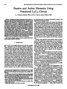
2. RESULTS AND DISCUSSIONS The models were numerically solved using the appropriate modules of Comsol Multiphysics software package, and by applying to a micromixer with two inlets and three outlets, allowing to split flow between mixed and nonmixed liquids. The total length of the channel is 940 μm and it is splitted in three narrower channels of 20 μm width, by obstacles having 50 μm length and 20 μm width. The inlets have 50 μm width and the depth of the structure is 50 μm. First configuration is illustrated in figure 1:
c) Fig. 2. Velocity distribution in micromixer (a) classic case; (b) based on the model; (c) variation along bottom channel corresponding to methanol inlet (A-B axis).
In classic case (fig. 2a), the velocity depends on water properties only, it is symmetrical about the middle longitudinal axis and reach its maximum (1.58 mm/s) in the middle of each channel. In the case of mixture model (fig. 2b), the velocity follow the viscosity profile. Since the methanol has lower viscosity, the maximal velocity (2.67 mm/s) is reached in the bottom channel, where the methanol concentration is higher. In this channel, the local maximum decrease with distance from inlet (fig. 2c) due to mixing process that decrease the methanol concentration and lead to a higher viscosity in the presence of water. The influence of methanol lower viscosity on velocity is also presented in figure 3 by velocity isolines, which are symmetrical in classic case (fig. 3a) and illustrate the methanol flow in model approach.
Fig. 1. Basig configuration of first microfilter design
Two sets of liquids were considered in simulations: water-methanol and water-glucose solution 30%. The properties at 200C are given in table 1: Table 1. Liquids properties Liquid Water Methanol Glucose 30%
Density g/cm3 1 791
Viscosity (mPa·s) 1 0.55
1.127
3.181
412
In figure 7 distribution of glucose volume concentration is illustrated. The diffusion is much slower than in classic case due to increased viscosity of mixture. The mean value of 0.5 is obtained in the region of bottom channel, corresponding to glucose inlet.
a) b) Fig. 3. Velocity isolines at inlet (a) classic; (b) model.
Fig. 7. Distribution of glucose volume fraction based on the model.
a)
The systems that use micromixers to initiate chemical reactions in biochemistry analysis more need often a perfect mixing of reactants. Since the model can be used to predict more accurately the regions where liquids are fully mixed, it can be use to optimize the mixer design. In case of micromixer with obstacles, the outlet can be configured in the outlet region where liquids are fully mixers, while the rest of liquids are supplied in different outlet ports and can be turned to inlet chambers. Figures 8 and 9 show the configuration of optimized mixers having outlet dedicated to region of fully mixed solution.
b) Fig. 4. Distribution of methanol volume fraction (a) classic; (b) model.
Distribution of methanol concentration in terms of volume fraction is presented in figure 4. Distribution obtained based on classic approach show that perfect mixing (0.5) is obtained in middle channel and outlet; it depends on constant diffusion coefficient (fig.4a). When variable diffusion coefficient is used, the volume fraction in the middle is around 0.62, while the value of 0.5 that represents perfect mixing is obtained closer to upper outlet (fig.4b). A comparative variation (classic vs. model) of methanol volume fraction along the each channel is represented in figure 5.
a)
Fig. 5. Methanol volume fraction variation along center of each channels.
b) Fig. 8. Distribution of methanol volume fraction (a) first optimized design; (b) second optimized design.
Similar results are obtained for mixing water (top inlet), and glucose solution (bottom inlet). The 30% glucose has three times greater viscosity than water, and maximum velocity (1.34 mm/s) is obtained in top channel (figure 6).
Fig. 9. Distribution of glucose volume fraction in optimized design.
Fig. 6. Velocity distribution for water and glucose mixing.
413
The positions of regions where liquids are well mixed are illustrated in figure 10, along with variation in cross point close to outlet splitter. The distance on x axis is related to bottom side.
References [1]
[2]
[3]
[4] [5]
a)
[6]
[7]
[8] b) Fig. 9. Variation of volume fraction across the channel in the vicinity of outlet. [9]
3. CONCLUSIONS In this paper we modeled a variable diffusion coefficient for miscible liquids that depends on local concentration and properties of each mixing liquid. We used this model in simulation on a passive micromixer considering two sets of liquids: water and methanol and water with glucose solution. The results obtained for velocity and concentration distribution are discussed and compared to results obtained by classic approach. Based on the model, that offers more accurate predictions, the design of micromixer is optimized in order to obtain full mixing at specific outlet.
[10]
[11]
[12]
[13]
Acknowledgement–The research presented in this paper is supported by the Sectorial Operational Programme Human Resources Development (SOP HRD), financed from the European Social Fund and by the Romanian Government under the contract number POSDRU /89/1.5/S/63700.
[14] [15]
414
V. Hessel, H. Löwe, F. Schönfeld, “Micromixers—a review on passive and active mixing principles”, Chemical Engineering Science 60, pp. 2479–2501, 2005. Nam-Trung Nguyen and Zhigang Wu, “Micromixers - a review”, Journal of Micromechanics and Microengineering 15, pp. R1– R16, 2005. A. Asgar, S. Bhagat, E.T.K. Peterson and I. Papautsky, “A passive planar micromixer with obstructions for mixing at low Reynolds numbers”, Journal of Micromechanics and Microengineering 17, pp. 1017–1024, 2007. S.H. Wong, M.C.L. Ward and W.C. Wharton, “Micro T-mixer as a rapid mixing micromixer”, Sensors and Actuators B 100, pp. 365–385, 2004. S.J. Park, J.K. Kim, J. Park, S. Chung, C. Chung and J. K. Chang, “Rapid three dimensional passive rotation micromixer using the breakup process”, Journal of Micromechanics and Microengineering, 14, pp. 6–14, 2004 A.D. Stroock, S.K.W. Dertinger, A.Adjari, I.Mezic, H.A. Stone and G.M. Whitesides, “Chaotic mixer for microchannels”, Science; 295, pp. 647–651, 2002. D.S. Kim, S.W. Lee, T.H. Kwon and S.S. Lee, “A barrier embedded chaotic micromixer”, Journal of Micromechanics and Microengineering, 14, pp. 798–805, 2004. P.B. Howell, D.R. Mott, S. Fertig, C.R. Kaplan, J.P.Golden, E.S. Oran and F.S. Ligler, “A microfluidic mixer with,grooves placed on the top and bottom of the channel”, Lab on a Chip; 5, pp. 524–530, 2005. C.C. Hong, J.-W. Choi and C.H. Ahn, “A novel inplane,passive microfluidic mixer with modified Tesla structures”, Lab on a Chip, 4, pp. 109–113, 2004. J.M. Park, K.D. Seo and T.H. Kwon, “A chaotic micromixer using obstruction-pairs”, Journal of Micromechanics and Microengineering, 20, pp. 15023–1503, 2010. R.H. Liu, M. Stremler, K. Sharp, M. Olsen, J. Santiago, R. Adrian, H. Aref, and D. Beebe “Passive mixing in a three-dimensional serpentine microchannel” J. Microelectromech. Syst. 9, 190– 197, 2000. R. Lindken, J. van Esch, B. Wieneke and J. Westerweel, “Characterization of advective microscale mixing in 3d by means of a stereoscopic particle imaging system”, Proceeding of 12th International Conference on Miniaturized Systems for Chemistry and Life Sciences, San Diego, California, USA, pp. 724–726, 2008. A. Stroock, S. Dertinger,A. Ajdari, I. Mezic«, H. Stone, G. Whitesides, Chaotic mixer for microchannels, Science 295, pp. 647–51, 2002. Comsol Documentation, “Chemical Engineering Module User’s Guide”, Comsol AB, 2008. C. Crowe, M. Sommerfeld, and Y. Tsuji, “Multiphase Flows with Droplets and Particles”, CRC Press, 1998.